CHAPTER 7 - WWII JAPANESE MILITARY TACTICS - SECTION 4

SECTION I - DOCTRINE.
1. GENERAL.
Japanese employment of fortifications is closely linked with their basic tactical aversion to the defensive. As a result of comparatively recent experiences, however, they have decided that their conventional perimeter-type defense is not satisfactory against an enemy with supeior naval and air power. On Peleliu, Iwo Jima, Okinawa, and in certain parts of Southeast Asia, the Japanese accordingly organized their defenses in considerable depth in order top assure the flexibility and elasticity which they now consider essential.
2. BASIC PRINCIPLES.
The Japanese have established certain principles and methods of construction for their fortifications, but actual practice seldon agrees with their textbook theories. Standard designs for permanent and field fortifications and obstacles have been provided, but construction varies in different localities according to the terrain and strategic importtance of the defended area.
Unlike Germany, whose fortified zones were confirmed to the European continent and followed certain general patterns, Japan has been compelled to fortify every conceivable type of terrain in widely separated regions form the tropics to the arctic. Consequently, Japanese fortifications generally will conform as nearly as possible to the surrounding terrain, and maximum use will be made of local and natural materials in their construction.
In outlying bases, concrete is used when other materials are not available, provided it can be shipped to the area. Where there are important strategic areas to be fortified, such as Saipan, Peleliu, Iwo Jima, and other areas in the inner zone inckuding the homeland, the use of concrete fortifications is specified and given high priority. When concrete works are used, they are supportedby open field works. These field fortifications are used to cover dead spaces, to engage enemy forces attempting to assault the concrete works, and to add some degree of flexibility to the beach line defense.
3. SITING OF FORTIFICATIONS.
Emplacements and pillboxes, designed to be mutually supporting, are covered by riflemen in field works around the position. The siting of fortifications isdetermined largely by the terrain as well as by the tactical requirements. Field of fire, observation, and natural obstacles are primary considerations, but, in many cases, concealment and inaccessability of positions take precedence over the other requirements.
Inmountainous terrain. or where there are hills coming down to the sea, defensive positions mey be sited inland or high ground overlooking the beaches. In this case, few obstacles may be found on the beaches themselves, but strong fire power will be available from well concealed and well constructed inland emplacements.
4. PERIMETER DEFENSE.
The early Japanese theory of perimeter type defense was followed primarily on coral atolls or islands, the narrowness of which greatly limited, but did not prohibit, some defense in depth. In such situations, defensive works have been found in a continuous band manned by troops who were committed to action from the outset. Antitank ditches, barbed wire, and strong points, consisting of groups of pillboxes, were laid out in accordance with the nature of the ground and the best approaches from the sea,
5. USE OF SHELTERS DEFENSE.
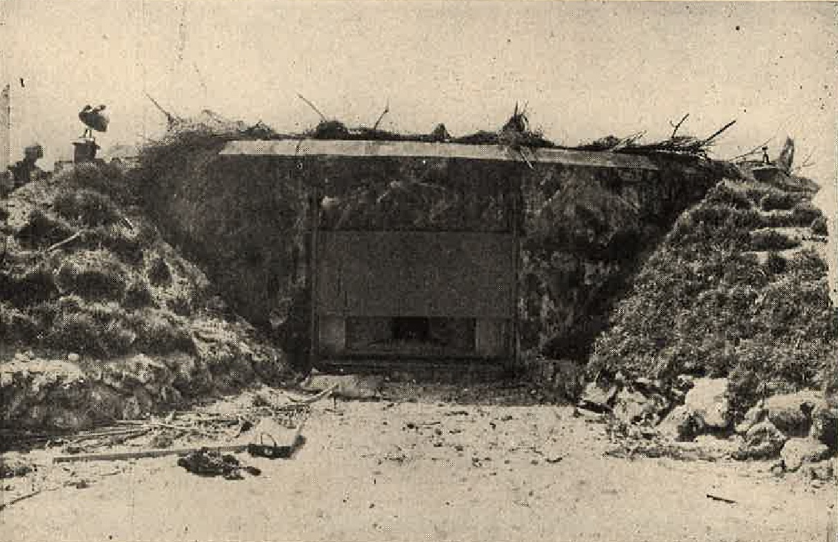
Figure 13. Stepped embrasure showing steel closure. |
Present Japanese doctrine includes the use of shelters in conjuction with weapons emplacements sited in depth to take
advantage of terrain. The shelters are constructed under, or close to pillboxes and emplacements. If a beach
area is to be contested, the Japanese withdraw to their shelters during the heavy naval nad aerial bombardment that
precedes an Allied landing.
They subsequently emerge and man the defenses when the barrage has lifted, and the Allied assault waves have hit the beaches. In the interior, shelters usually are provided with underground connection to gun positions. |
6. COMMUNICATION TRENCHES.
|
Communication trenches, which protect personnel moving between positions within a defended locality, are used to connect
weapons positions, fox holes, observation posts, and similar installations. In positions containing permanent fortifications,
such trenches connect the principal forts and pillboxes with secondary weapons emplacements.
These communication trenches may be open or covered. In most cases, emplacements have an entrance trench leading a short distance to the rear and connecting with a main intercommunication trench. Prescribed depth varies from 4 feet for a one way trench to 5 feet for a two way trench. The trace may be wavy, zigzag, or echeloned; the spoil may be piled at the sides to increase the cover, or it may be carried away to facilitate concealment. |
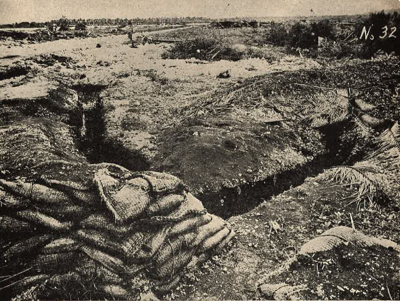
Figure 1. Typical Japanese communication trench on Guam. |
7. CAMOUFLAGE.
With few exceptions, Japanese defense installations are not only substantially constructed, but well concealed. The Japanese are expert in methods of using natural materials to blend their installations into the surrounding terrain. Wherever possible, living vegetation in the form of vines, bushes, and weeds is planted to provide effective concealment. IN barren rocky areas, the rocks themselves are used for camouflage purposes.
When no natural materials are available, artificial materials in the form of nets and paint are used. The Japanese are not very proficient in applying paint to their larger installations as a camouflage measure, and such positions therefore are usually easy to detect.
 |
 |
Much of the camouflage used in connection with Japanese defenses takes the form of deception.
Dummy gun emplacements are frequently encountered. While many of the earlier ones were rather crude and eneffective, dummy positions recently have appeared that were quite realistic and difficult to differentiate from the real emplacements.
 |
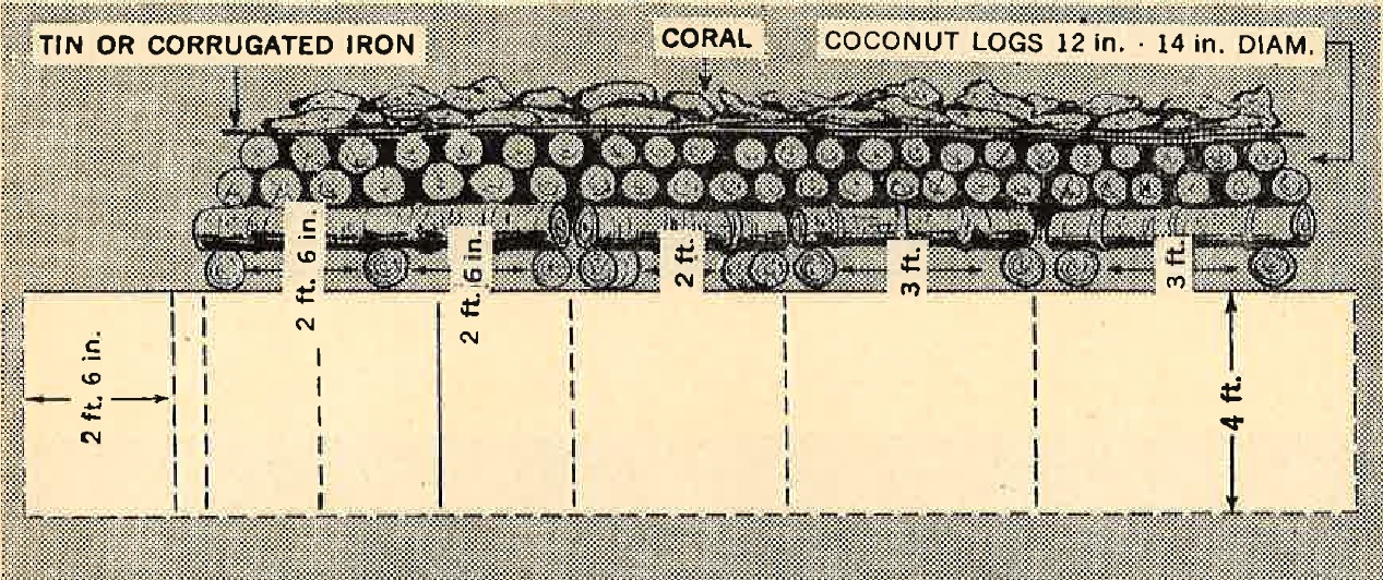 |
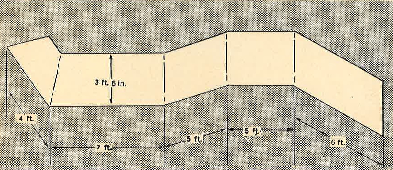
Figure 3. Typical log-and-earth construction.
SECTION II - PERMANENT FORTIFICATIONS.
1. CHARACTERISTICS.
a. Siting. The spacing of permanent structures has varied in different areas, and also within individual sites. In the Gona locality in New Guinea, one and two man log pillboxes were found only 3 to 5 feet apart over an extensive area. Six man pillboxes were found in the same locality 30 to 50 feet apart.
|
One large locality in Burma contained seven pillboxes in an area 200 yards long and 100 yards wide. On Tarawa,
pillboxes were located within 50 yards of the high water line, placed at about 25 to 50 yard intervals along
the entire perimeter of the island. On Kwajalein, one 500 yard stretch of beach contained three concrete,
two coral masonry, and two log pillboxes; and along the shore of a cove on Los Negros in the Admiralty Islands,
eight log pillboxes were located about 30 yards apart. In an area approximately 1,000 yards square on Iwo Jima,
900 pillboxes of various types were found.
b. Size and shape. The size and shape of the fortifications vary depending on their use, the military requirements, and the type of terrain. Perimeter shelters or sniper posts are designed to hold one or two men, while large fortifications inside the perimeter system or at key points may hold 40 to 50 men. Caves capable of holding 300 men have been found. The most common structure vary in size from 6 1/2 by 6 1/2 by 5 feet to 60 by 40 by 27 feet. They may be round, square, rectangular, or, ins some cases hexagonal or octagonal in shape. |
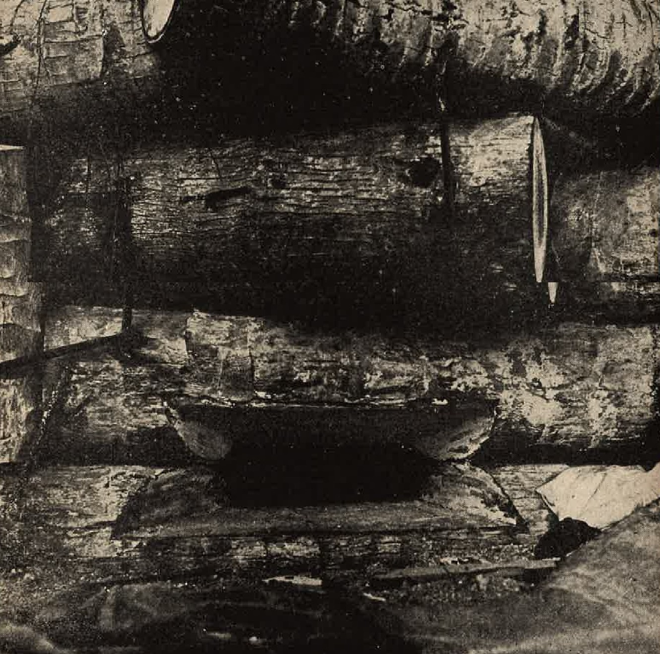
Figure 3. Front view of pillbox showing staples. |
Still others have irregular shapes. The thickness of roof and walls varies from 8 inches to 5 feet, and there may be from 2 to 8 feet of earth and other natural materials covering the structure.
Apparently there is no relation between the size of structures and the thickness of their roof and walls. some of the largest concrete air raid shelters have roof and walls measuring only 2 feet thick, while those command posts often are 3 to 5 feet in thickness.
2. CONSTRUCTION.
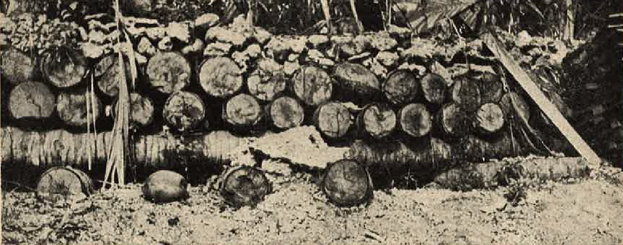
a. Log-and-earth type installations. In heavily wooded or jungle terrain, positions are usually well dug in and then built up with a framework of log columns and beams. Walls are revetted with additional logs.
The logs vary in size fron 4 inches to 24 inches in diameter, the average being 12 inches. As many as four thicknesses of logs are used to form the roof of the structure. This in turn is covered by alternating layers of dirt or sane and rocks, the whole cover varying in thickness from 2 to 8 feet.
Fuel drums filled with earth may be used instead of logs to reinforce the walls of the installation and to form weapons embrasures. When available, railroad ties and rails are used for reinforcing purposes.
Coconut palm logs are the type most commonly used in the pacific theater, because they are usually easily obtainable in most tropical islands, and are more splinter proof against bombs and shells than other types of logs. However, upon aging, these logs tend to become soft and spongy, and instances have been noted where .30 caliber bullets had perforated 12-inch logs.
The logs are joined together in several different ways. The majority of them have been fatened together with staples, but wire has laso been used for this purpose.
Some logs are notched and recessed at intersections, while some are merely driven into the ground side by side. The best use of available construction materials seems to be the only governing principle.
Compared with concrete installations, the log-and-earth type are naturally weaker, but generally a direct hit from a bomb or heavy shell is needed to reduce completely one of the positions.
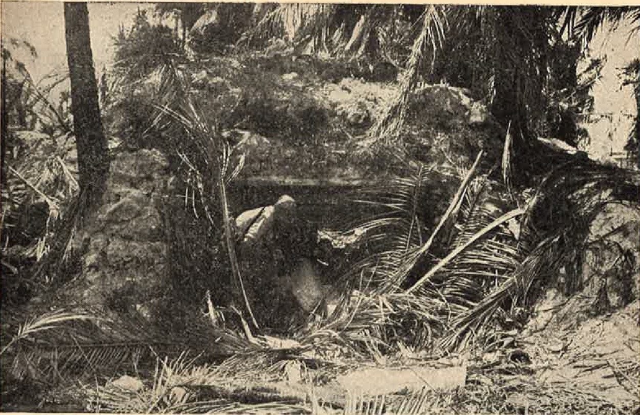
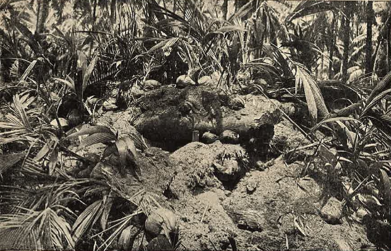
Figure 8. Pillbox camouflaged with earth and cut vegetation. |
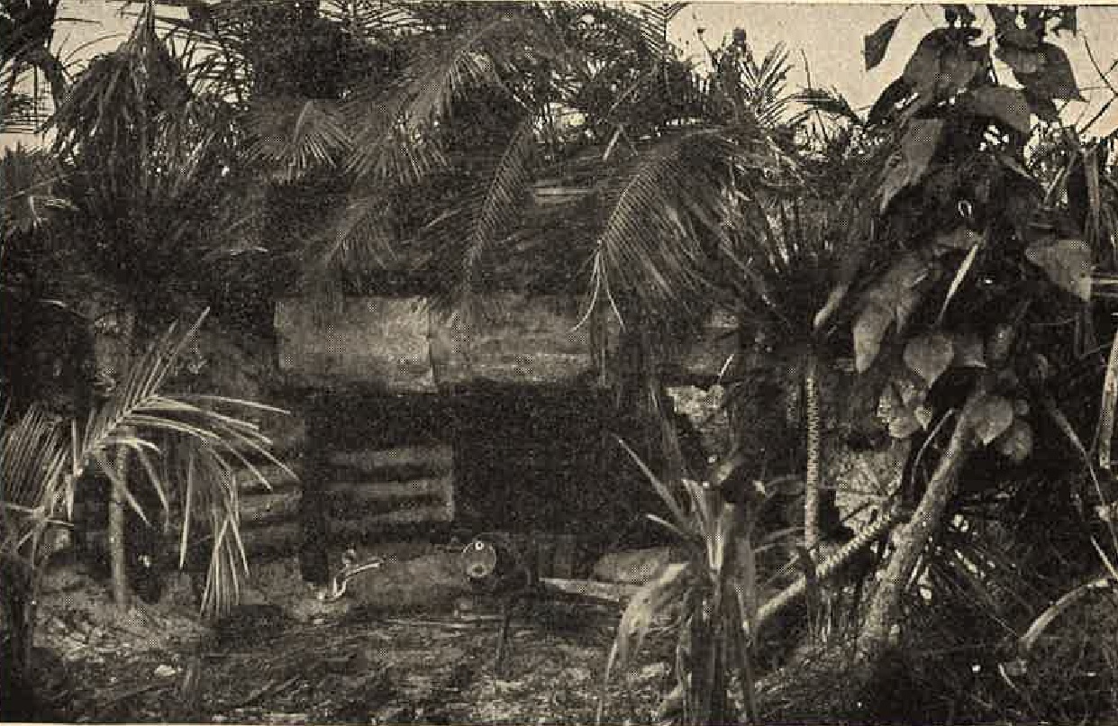
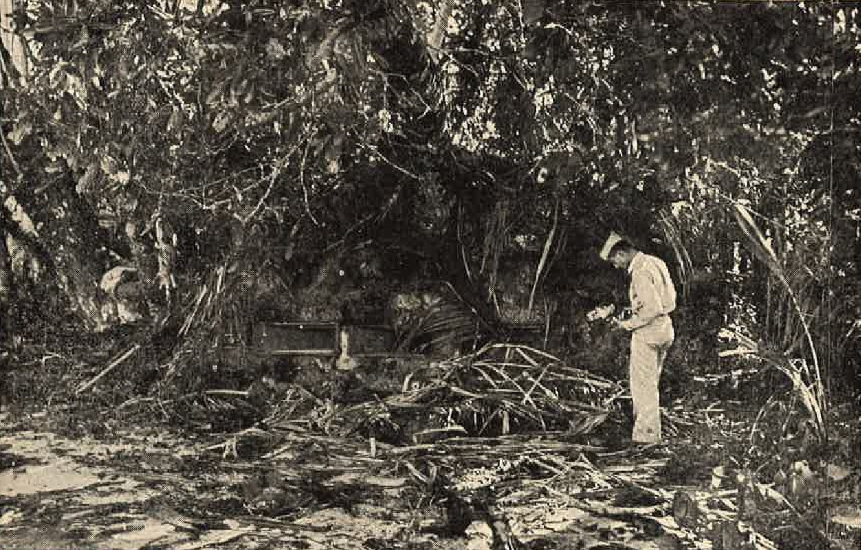
Figure 9. Pillbox camouflaged with live vegetation. |
|
b. Concrete installations. important installations, such as command posts, shelters for high ranking officers, and
certain weapons emplacements usually are constructed with reinforced concrete, or are located in caves. Where the cement
has to be shipped to outlying island strongholds, orders are issued to conserve it as much as possible by adding crushed
rock and coral in excessive amounts.
The usual Japanese concrete formula is one part cement, two parts sand, and four parts gravel by volume. When coral rock is used, the formula is changed to one part cement, three parts sane, and three and six-tenths parts of crushed coral aggregate. Ordinarily about 18.75 pounds of cement are used per cubic foot of concrete. Information on the actual strength of Japanese concrete works in all areas where they have been encountered is not available at the present time. 
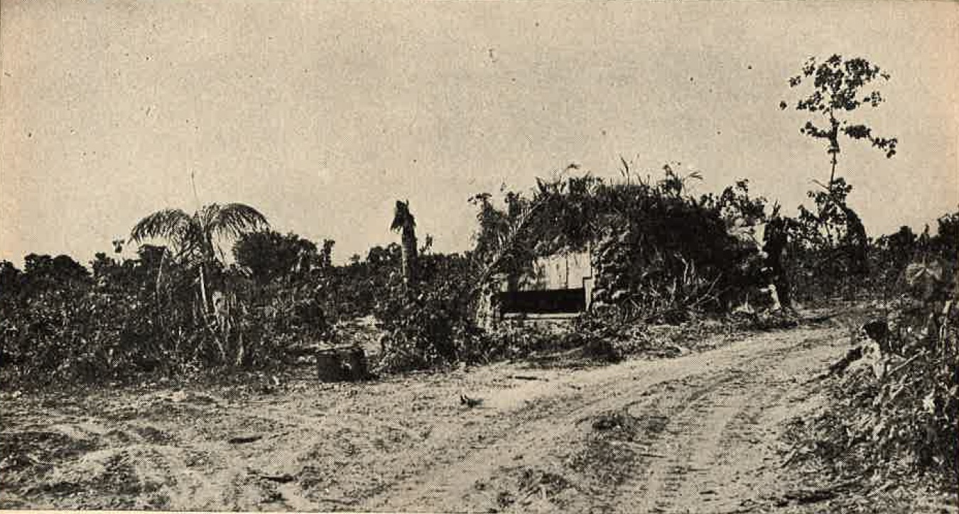
Figure 10. German-type pillbox showing vegetation used for camouflage. |

Figure 14. Details of German-type pillbox. This pillbox was designed for 13.2-mm machine guns, but the 20-mm rapid fire cannon has also been emplaced in it. |
Generally, the concrete was considered to be inferior to U.S. concrete, and in some cases there is specific proof that this was the case. It was noticed also that the strength of the concrete varied in different areas. The concrete used in fortifications on the Marshall islands was weaker than that used in Tarawa. On Kwajalein Atoll, the strength varied on different islands; in comparison with the class A concrete expected to be found in modern fortifications, it was all of very poor quality.
 |
 |
There are several probable reasons for the inferior grade of Japanese concrete encountered thus far (1944). On many of the islands crushed coral was used as an aggregate, and this is a poor material for that purpose in comparison with crushed stone. Salt water in mixing also weakened the concrete, and in many cases insufficient cement was used. Then, too, the Japanese are not experts at pouring concrete, as eveidenced from lines of cleavage observed in many of their structures.
Analysis of concrete used in the Marshalls disclosed numerous air voids, an indication of hasty construction. These voids, in addition to the coral aggregate used, would account for the low density and strength of the finished concrete. Japanese concrete found in the Marianas, the Palaus, and on Iwo Jima, however, seems to be of much higher quality, and this will probably also be true of concrete in defense installations on the homeland.
Figure 16. Coral masonry pillbox. Found on the island of Peleliu. The following classification table was used by the Japanese in constructing their fortificatins at Peleliu. Construction in other areas probably approximates these specifications fairly closely. |
Figure 17. Details of coral masonry pillbox. |
| Classification | Standard of Strength | Reinforced concrete | Coral and rock wall | Piled rock and brick | Regular soil | Notes |
| Special A | Safe against direct hit of 1-ton bomb or 16-inch shell. | 9.75 feet. | 16.5 feet. | ----- | ----- | Utilize the steep sloped cliffs and rocks and make a gallery type shelter. (cave). |
| Special B | Safe against direct hit of 500-pound bomb or 8-inch shell. | 5 feet. | 8.25 feet. | ----- | ----- | Utilize the steep sloped cliffs and rocks and make a gallery type shelter. (cave). |
| A | Safe against direct hit of 220 pound bomb or 6-inch shell. | 2.6 feet. | 5 feet. | 6.5 feet | 26 feet. | Construct principally with reinforced concrete, rock, or hard wood. |
| B | Safe against hit of 100-pound bomb or 3-inch shell. | 1.6 feet. | 2.6 feet. | 4 feet. | 16.5 feet. | Construct principally with reinforced concrete, rock, or hard wood. |
| C | Safe against 35-pound bomb or live fragments. | 1 foot. | 1.6 feet. | 2.3 feet. | 6.5 feet. | Construct principally with reinforced concrete, rock or hard wood. |
| D | Safe against 13-mm or smaller MG bullets and small live fragments. | 2.5 inches to 4 inchs | 9 inches | 9 inches | 3.25 feet | -------------- |
| Classification | Types of terrain and soil | Installations | Notes |
| Special A | Rocky place or steeply sloped terrain. | Important CP, OP, or radio communication post. | Cave type. |
| Special B | Rocky or steeply sloped place. | Important shelter or cover. | Cave. |
| B | Gravel beach | Vital gun (flank protecting artillery) emplacements or CP. | Reinforced concrete. |
| A | Rocky place or gravel. | Important gun emplacements (guns bigger than MGs), CP of high officer, OP, important radio communication pot, and shelter for important gun. | Mainly reinforced concrete. |
| B | Place that would be hard for enemy to destroy. | Gun emplacement (guns bigger than MGs), shelter (for personnel, arms, and ammunition), CP for lower ranking officers and OP. | Principally reinforced concrete, piled rock, dirt and wood. |
| C & D | Place where there is not much danger of enemy fire. | Heavy-weapons emplacement and reserve position of the same; main LMG position; lookkout station; shelter for several men; small ammunition storage place; and shelter for arms, food, and water. | Mainly of dirt and wood, and piled rocks. |
Figure 5. Detail of reinforcing rods in Japanese bomb proof shelter. |
The size and quantity of reinforcing rods vary according to the thickness of walls and roof of the installation,
and according to the purpose for which they are used. Generally, 1/2 inch steel rods are placed on 8-inch
centers horizontally and vertically on both the inner and outer faces of small concrete pillboxes and shelters.
In the heavier type pillboxes, casemates, and large shelters, 1-inch bars are used in as many as four layers in a 4-foot wall. They are placed on 6-inch centers, both horizontally and vertically. Usually the reinforcing rods are hooked at both ends are fastened together with wire where they cross each other. In heavier construction the steel rods are sometimes fastened together with stirrups. In prefabricated structures with walls less than 1 foot thick, No. 8 steel wire is inserted in criss-cross fashion at 8-inch intervals. 3. TYPES. a. Pillboxes. (1) Log-and-earth type. Installations constructed of logs, earth, and local materials were used extensively in the South-west Pacific area, but they have also been encountered in the Marianas, Palaus, the Philippine islands, and in Burma. Similar structures supplementing concrete works, will probably be found in other Japanese held areas. Figure 6 shows a typical light machine gun pillbox constructed of natural materials. Most of these pillboxes have a protective or grenade wall constructed of logs inside the entrance to prevent firing into the pillboxes. Grenades thrown so that they fall in the entrance space can be kicked behind the wall to explode without causing casualties among the occupants. Another device which affords protection against grenades is a grenade well in the floor of the pillbox. When a grenade is thrown through the embrasure it is kicked into the well where it explodes with less chance of |
injuring the occupants. Often a small ditch is prepared in front of embrasures of Japanese pillboxes to catch debris and earth dislodged by exploding shells and bombs, thereby preventing the obstrution of the embrasures.
Pillboxes constructed of natural materials such as logs, rocks, earth, and sand are comparatively easy to camouflage, since materials used for consructionblend with the area where the installation is sited. Good camouflage is the rule rather than the exception with the Japanese, and it is possible to approach within 50 feet of these pillboxes and not detect them.
 |
 |
Examples of camouflaged log-and-earth type pillboxes are seen in Figures 8 and 9. In viewing these illustrations, it should be remembered that most of the natural camouflage had been removed in order to disclose the installation itself.
 |
 |
(2) Concrete type. Although several designs for concrete pillboxes have been standardize, the Japanese seldom adhere to them in the field. One type, however, which has appeared in the Marshall, Marianas, and Palau islands, and whihc may be considered standard, is the circular German-Type pillbox, often referred to as a "blockhouse".
This is one of the strongest known Japanese pillboxes, it is 40 feet in diameter, with walls 4 feet in thickness and a ceiling of 2 1/2 feet thick. The concrete is reinforced with four rows of double 1-inch steel bars, placed in criss-cross pattern at intervals of 6 inches.
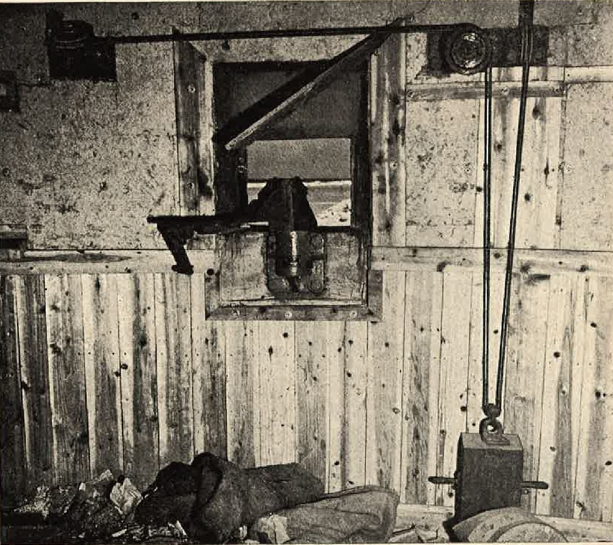
Figure 11. Interior showing pulley system for operating embrasure closure plate. |
Four embrasures are provided, each with a sliding 1/4-inch steel closure plate, which is operated by a pulley
device from the interior. There is a steel observation turret extending 3 feet above the center of the roof.
Slots in the turret provide ventillation as well as observation. The embrasures are stepped, following the
German design, in order to prevent rocochets from coming through the opening.
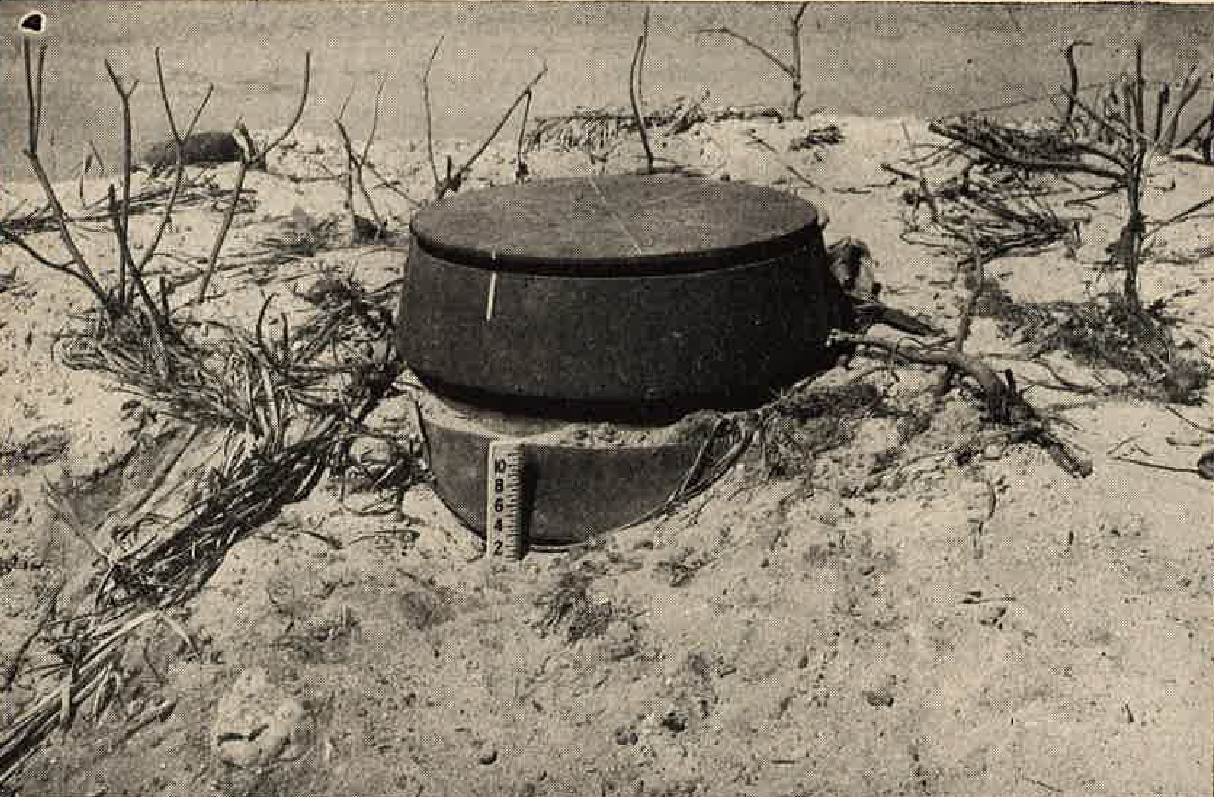
Figure 12. Top of pillbox showing onservation turret. |
The walls on the interior are wainscoated to a height of 2 feet and lined with a thick layer of rock wool. This acts as some measure of protection against spalling of the concrete and also aids in moisture prevention. Other details can be seen in Figure 14.
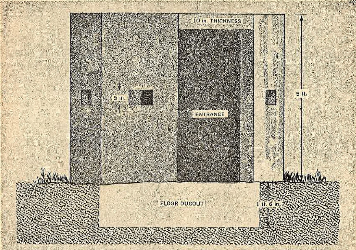
Reinforced concrete pillboxes similar to this octagonal shpaed structure are very often used as sniper posts and placed at cross roads and road junctions. The average size is about 6 1/2 by 6 1/2 by 5 feet. The walls are 8 inches thick, while the roof is 10 inches in thickness. Seven embrasures provide fire in all directions. The concrete is usually painted green to match the foliage, and because of its small size the structure is very easy to camouflage.
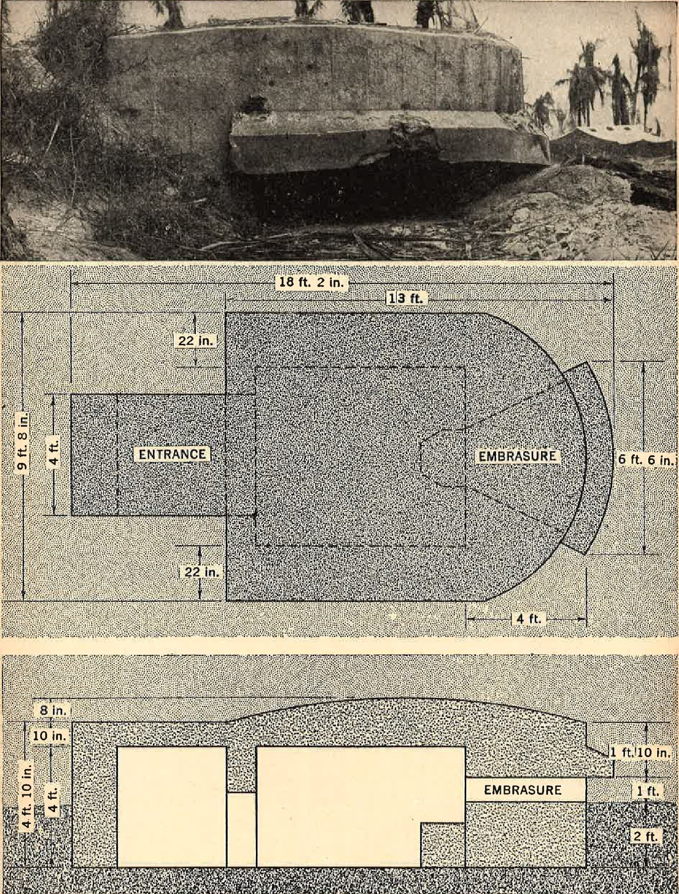
Figure 18. Single embrasure reinforced concrete pillbox. |
A good example of the Japanese ability to utilize local materials is this coral masonry pillbox found on Peleliu,
shown in Figure 16. In order to provide additional strength, the coral rocks forming the walls and roof were cemented
together. This, in conjunction with 8-inch logs and wooden planks, formed a very substantal pillbox. The walls
varied from 3 to 5 feet in thickness, while the total thickness of the roof measured 5 feet. Cement block pedestals
with wooden platforms for the machine guns, were erected before each of the three embrasures. This type of structure
is easily adaptable to any type of terrain, and may be constructed of local materials if cement is not available.
Pillboxes of the type illustrated in Figure 18, with only one embrasure, are generally found covering a beach area, and are sited to fire at predetermined targets such as a landing beach, antitank ditch, or barbed wire obstacle. They also may be found in inland areas sited to cover important road junctions or road blocks. The embrasure is built at ground level, so the whole structure has a low silhoutte, which aids in its concealment. Another type is the reinforced concrete pillbox with an underground magazine chamber shown in Figure 19. The magazine probably is used to store suppplies as well as ammunition. Many pillboxes and casemates have separate ammunition shelters located some distance to the rear of the actual weapons emplacement. A pillbox of this design, with five embrasures, may be sited to provide flanking as well as frontal fire and therefore may be found along antitank ditches or prepared defensive lines. |
|
The roof and walls are all 1 foot thick, and the roof of the shelter is generally covered with about 2 feet of earth,
so that only the embrasures and top of the pillbox are above the ground line.
b. casemates. (1) Log-and-eath type. Casemates for larger guns are usually constructed of reinforced concrete, or the guns may be placed in caves. However, casemates constructed of logs, coral rock, and earth are sometimes used for 75-mm field gun emplacements, and for antitank gun emplacements. |
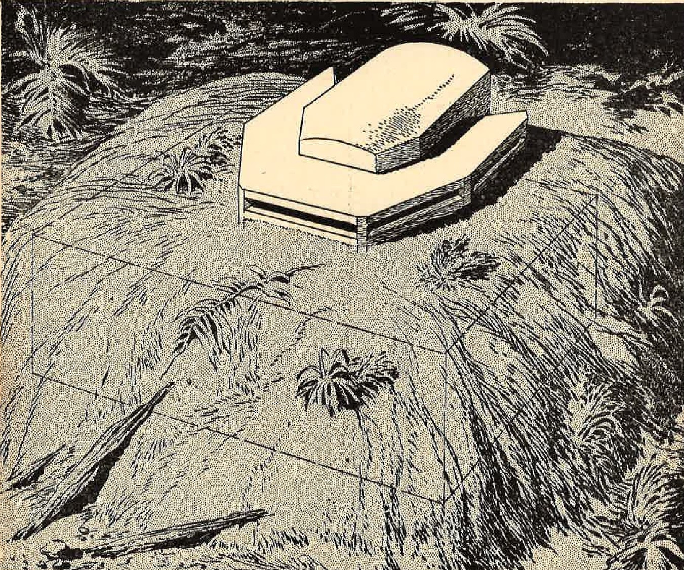
Figure 19. Pillbox with underground magazine. |
 |
 |
Figure 21 illustrates this type of structure. It was excavated in solid coral limestone and then lined with 8-inch logs on both roof and walls. A sheet of corrugated tin was placed over the logs on the roof, and coral and rock were piled on this for a thickness of 3 feet.
In all of these casemates a ramp is provided, usually in the rear, sometimes on the side, for removal of gun.
 |
 |
 |
 |
|
(2) Concrete type. Some coast defense guns are emplaced in reinforced concrete casemates, although thus far the
majority have been found in open emplacements and caves. Most of the concrete casemates are massive installations
with walls 3 to 5 feet thick and roofs varying from 2 1/2 to 4 feet in thickness.
The casemate (shown in Figure 23) for a 6-inch gun on Saipan is 33 feet long and measures 30 feet at the widest point. It is 15 1/2 feet high, although only about 7 feet extend above the ground level. Steel rods, 7/8-inch in diameter, and placed on 12-inch centers both horizontally and vertically, were used for reinforcing the concrete. Guns of 120-mm caliber used for coast defense are often placed in reinforced concrete casemates. Installations of this type were found on Saipan and Iwo Jima. Reinforced concrete underground magazines are usually provided near these casemates. |
Figure 23. Casemate for 6-inch coast defense gun. |
 |
 |
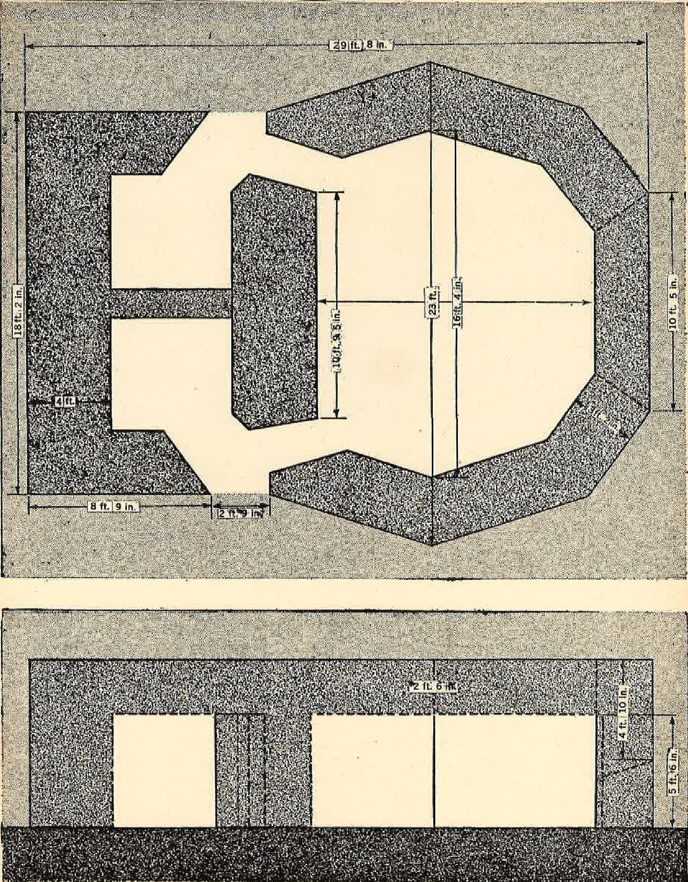
Figure 25. Casemate for 120-mm coast defense gun. |
The walls of the casemate shown in Figure 25 are 3 to 4 feet thick, and teh roof is 2 1/2 feet thick. Variations of this
type of structure have been found wth walls 5 feet thick and roof 3 1/2 feet in thickness. Practically all such casemates
have a separate compartment in the rear for personnel and supplies. This is also true of the majority of the larger pillboxes.
Concrete casemates are also provided for smaller guns such as the 75-mm mountain gun. 37-mm and 47-mm antitank guns, and the 20-mm antitank rifle. In addition to the large embrasure for the gun, smaller embrasures are sometimes provided for machine gun and rifle fire, as shown in Figure 26. 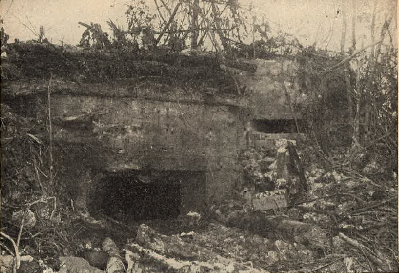
Figure 26. Concrete casemate for 75-mm mountain gun. Found in Peleliu. |
This installation, found in Peleliu, had walls 2 feet thick. The roof consisted of 3 1/2 feet of reinforced concrete and 4 feet of 12-inch logs surmounted by vegetation.
A design similar to this type was used in several pillboxes on Okinawa. The smaller embrasure was used mainly as an observation port by the gun captain in viewing his field of fire. These pillboxes were provided with a slab of concrete about 6 inches thick, which could be placed over the embrasure for protection and some concealment. The slabs were covered on the outside with paper about the same color as coral background for additional concealment.
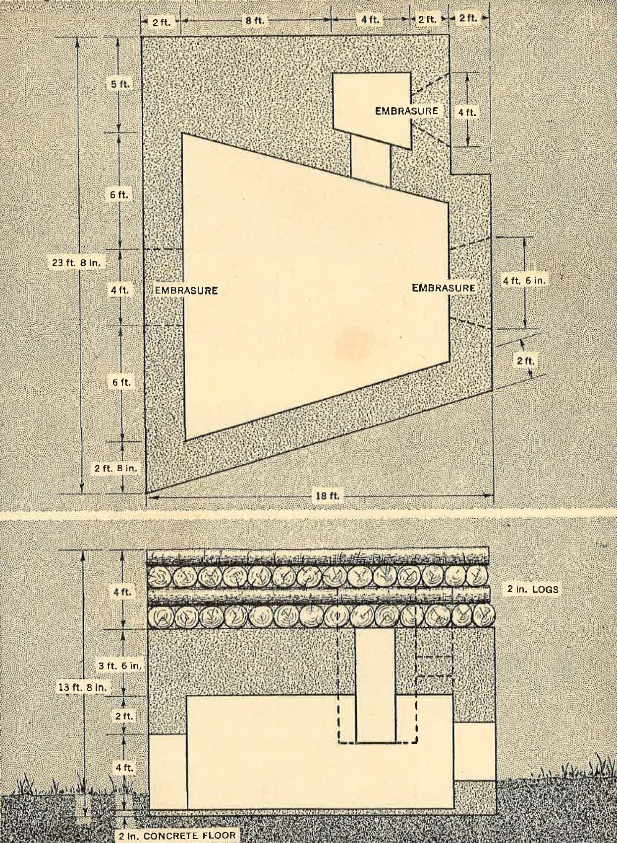
Figure 27. Details of concrete casemate for 75-mm mountain gun. |
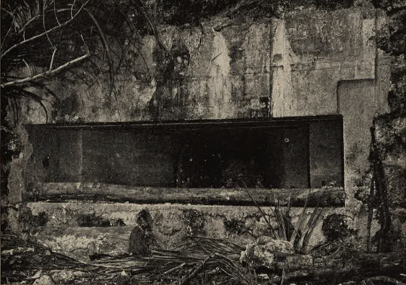
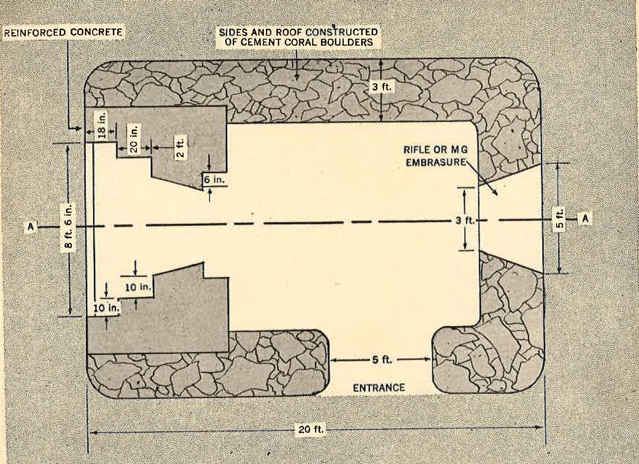
Figure 28 illustrates a concrete and coral casemate housing a 37-mm antitank gun.
The 5-foot thick roof consisted of coral rocks cemented together, supported by a layer of 6-inch to 9-inch log rafters and sheet tin. Two embrasures were provided, one for the antitank gun in the front, and the other for rifle or machine gun in the rear. The entire front end of the casemate surrounding the embrasure was made of reinforced concrete. The walls were 3 feet thick, and were also constructed of cemented coral rocks. Excellent over all camouflage made this installation very difficult to detect. |
 |
 |
 |
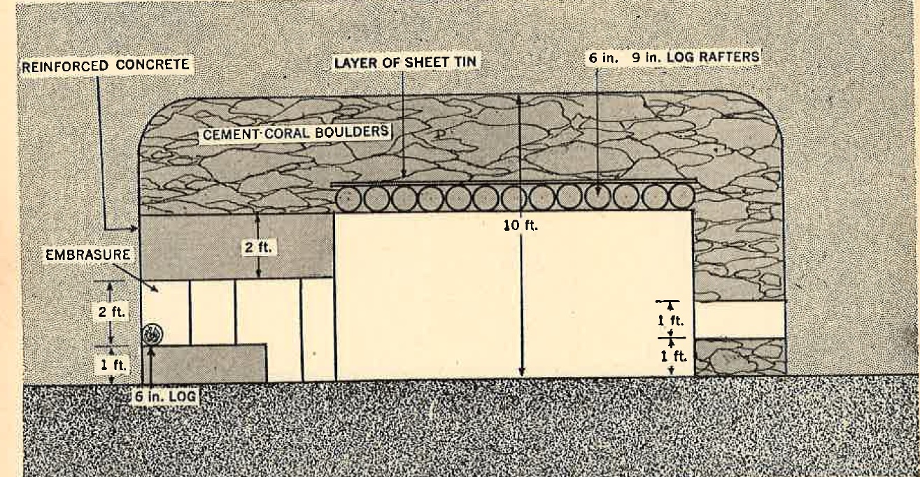 |
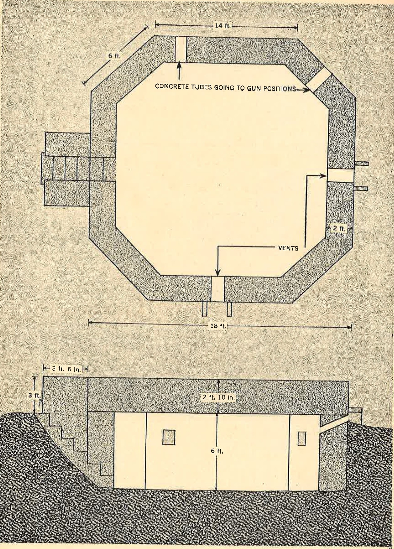
Figure 30. Concrete shelter for crew of 120-mm dual purpose gun. |
c. Shelters. In most of the Japanese defensive positions, the number of shelters used is far in excess
of the number of pillboxes and casemates. The shelters can be divided into two general classifications according
to the purpose for which they are used.
(1) Large personnel shelters. This type, usually located in barracks and headquarter areas, is designed to protect large groups of personnel during aerial or surface bombardment. Shelters of this type are also used as medical aid stations, command posts, and power plants, and for storage of supplies. These structures are large and have side walls and roofs that average 3 to 6 feet in thickness. Depending upon the area, they may be constructed of reinforced concrete, or of logs and natural materials, or they may be located in caves. Ventilation shafts are provided, but there are no gun or rifle embrasures. (2) Standby shelters. This type, generally located adjacent to defensive positions, is designed as a standby shelter for troops during bombardment, while waiting ro man their defense positions. These are smaller in size and lighter in construction than personnel shelters, but construction materials are the same. Although not designed as prepared defense positions, they are used as such in the later stages of the defense, when riflemen and machine gunners fire from the doorways. Recently, the trend in contruction of these shelters has been to dig underground as far as possible, and caves are being used to every advantage for this purpose. |
|
(3) Construction details.
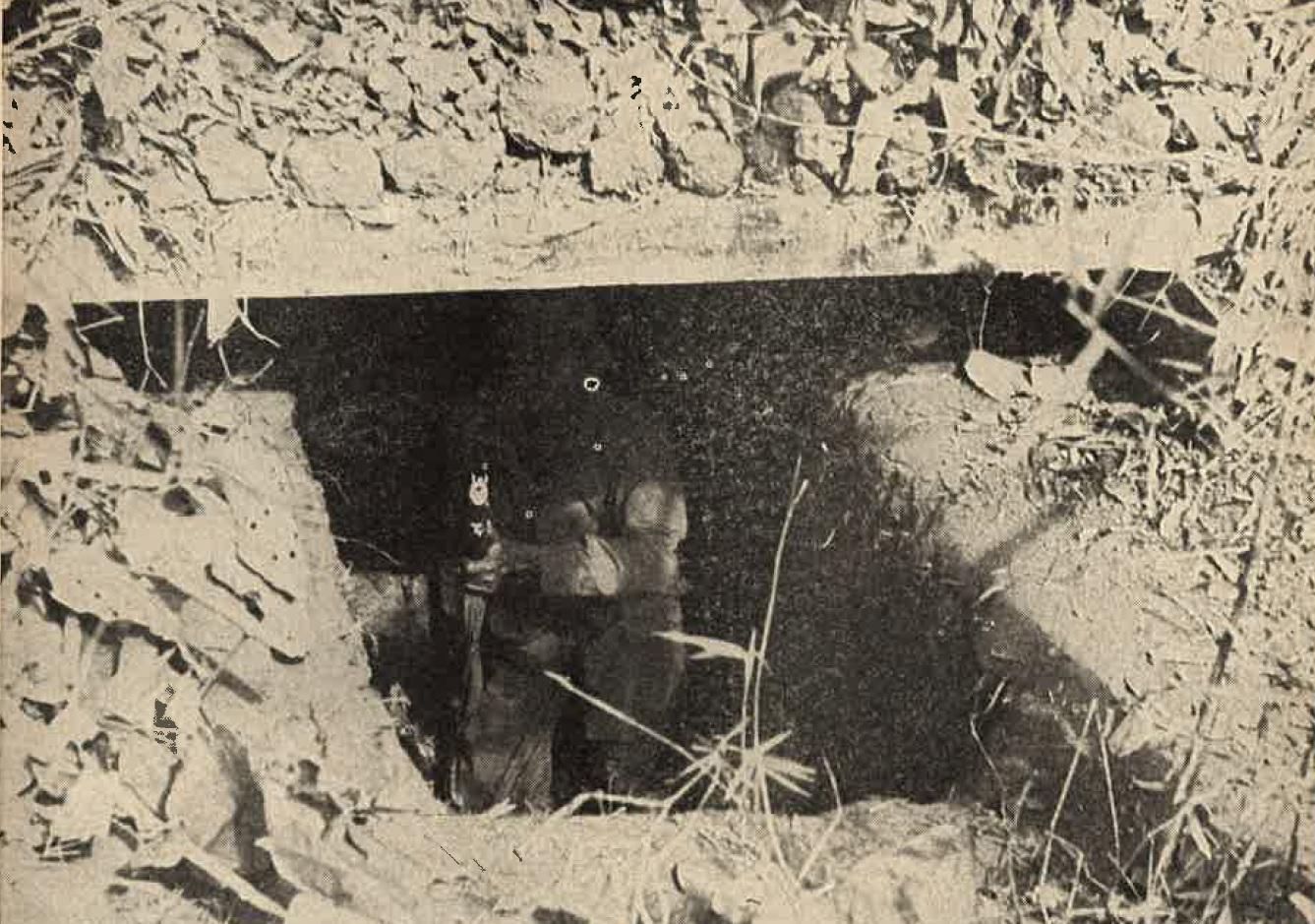
(a) Log-and-earth type Shelters constructed of teh usual log, earth and rock materials are very similar in construction to pillboxes, except they are usually stronger, and placed deeper underground if the water table permits. The various layers of logs, rocks and earth, as well as the sand filled fuel drums reinforcing the walls of a typical shelter, can be clearly seen in Figure 31. In New Guinea, shelters 40 feet long were found constructed of four thicknesses of 10 inch logs mounded over with coral and earth. Structures were observed in Burma that had roof timbers 18 inches in diameter, with cross members 30 feet long and 2 to 2 1/2 feet in diameter. Teakwood is used in many cases as top cover for air-raid shelters. |
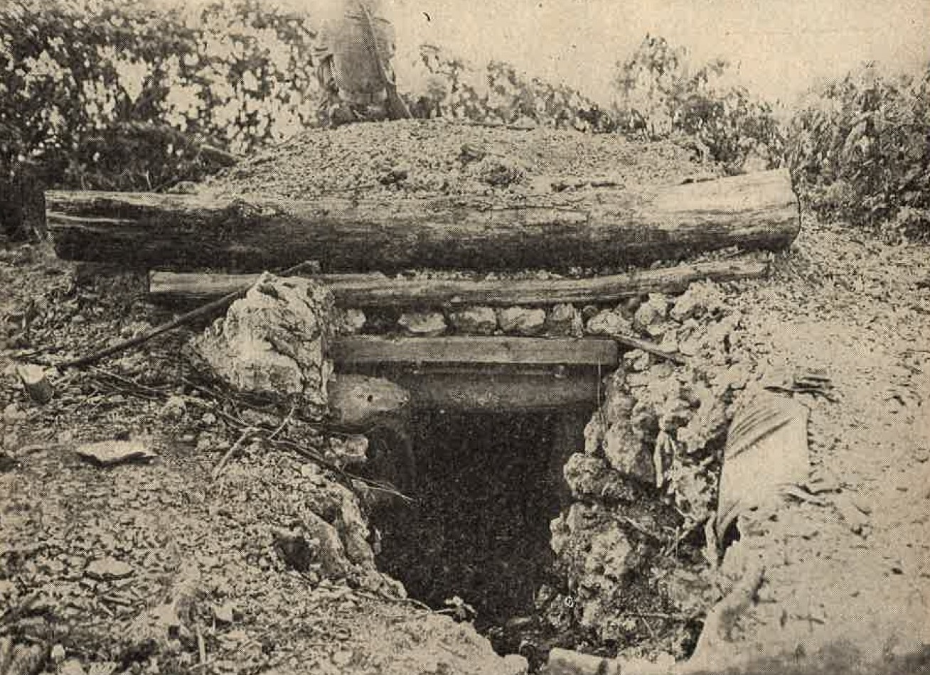
Figure 31. Typical entrance to log-and-earth shelter. |
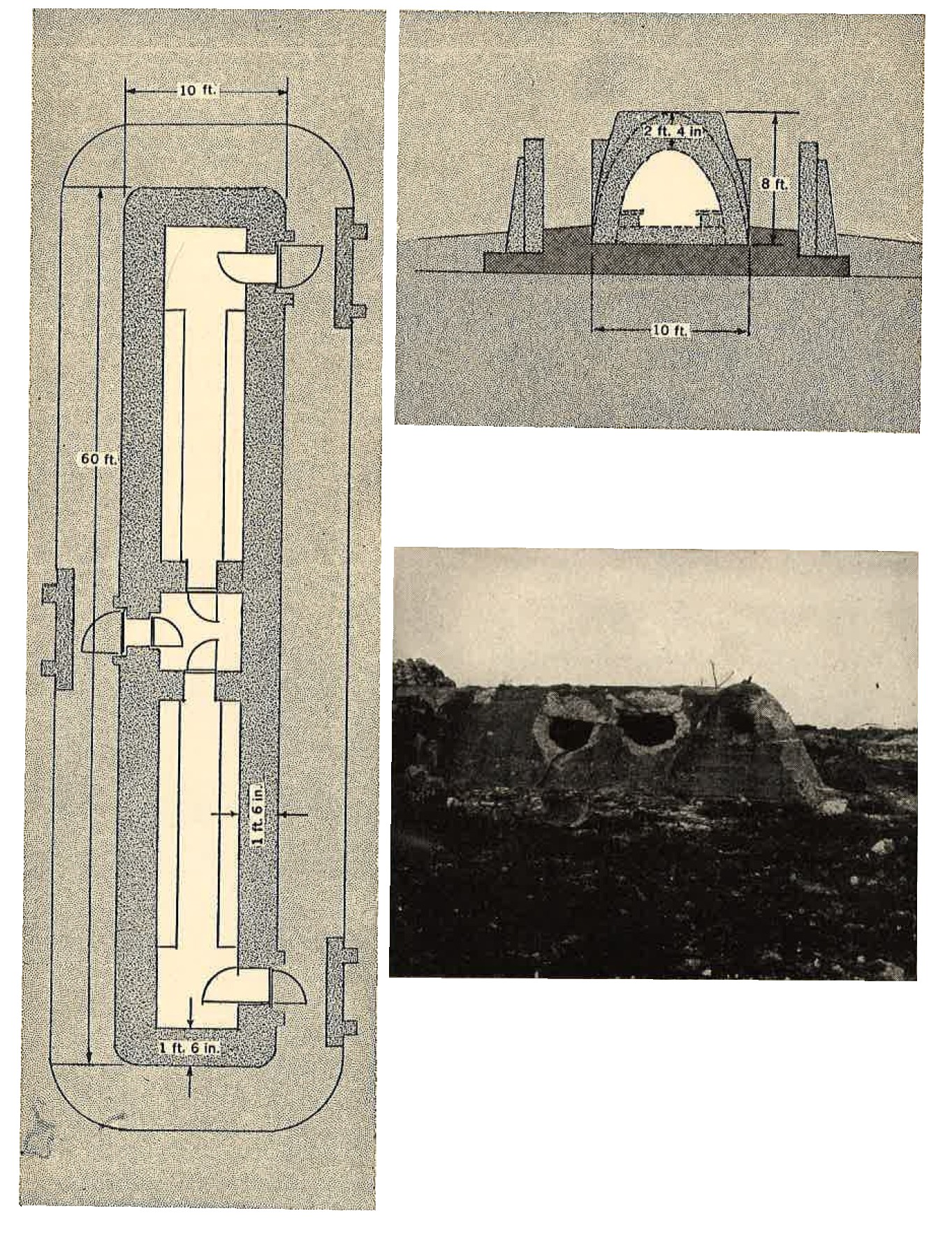
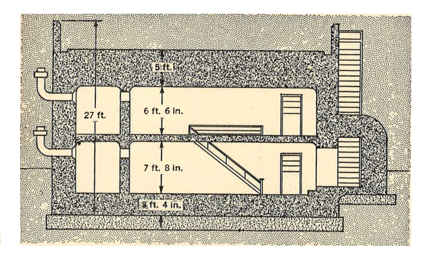
Figure 32. Typical concrete bombproof shelter. |
(b) Concrete type. Reinforced concrete shelters of varying sizes, but usually rectangular in shape, were used for
power plants, communication centers, command posts, and personnel shelters in the Marshall, Marianas, and Palau islands.
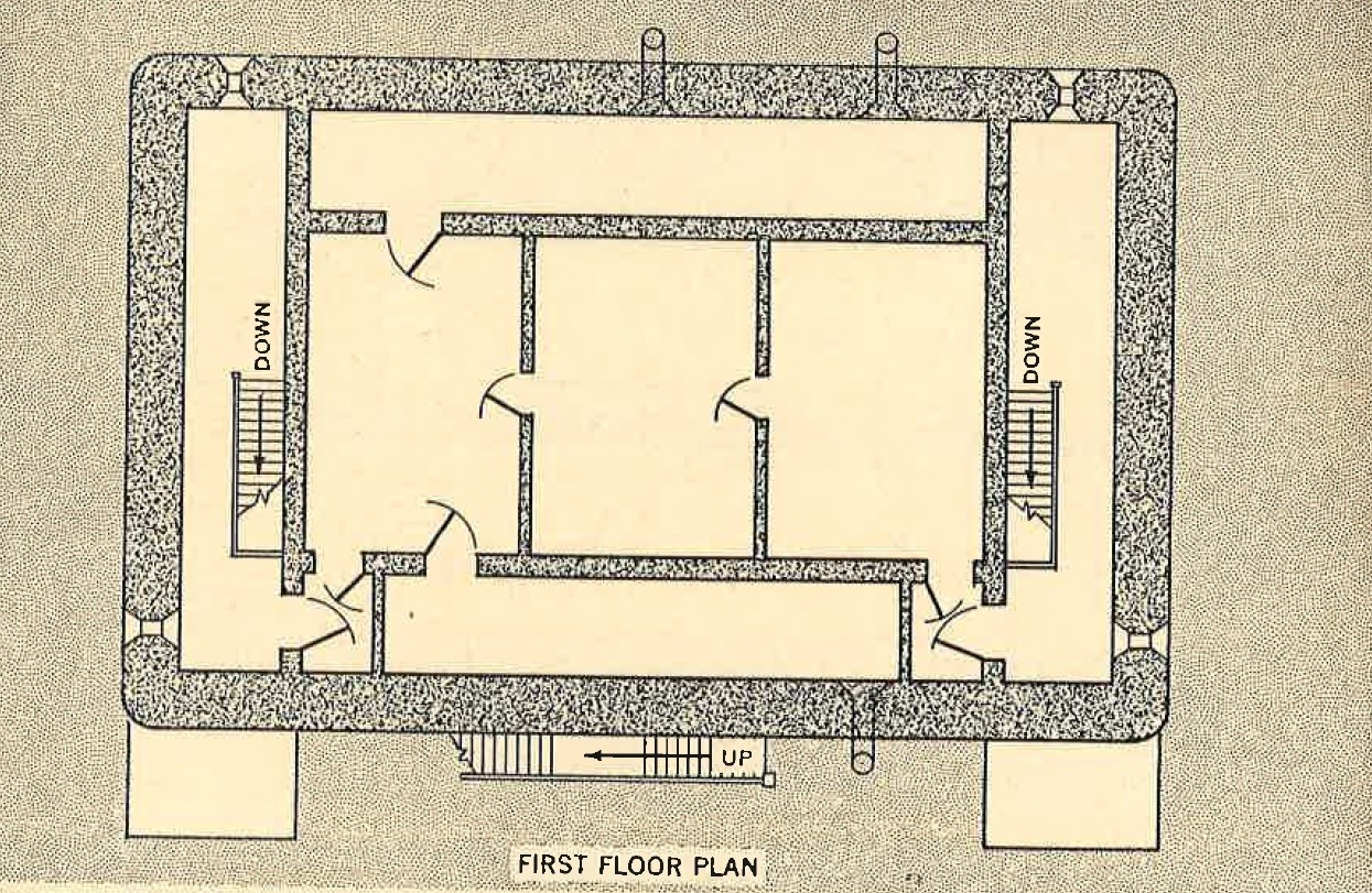
Most of the concrete bombproof personnel shelters are long structures arched in cross section as in Figure 32. They usually vary in length from 50 to 60 feet, in height from 6 to 12 feet, and in width from 6 to 15 feet. The maximum thickness observed in the walls was 4 1/2 feet, and 1 inch steel bars, criss crossed 9 inches apart both ways, were placed in both the inner and outer faces for reinforcing. The roof of these structures is almost always thicker than the walls, although some have been found where the reverse is true. Five feet of heavily reinforced concrete, with earth and rock piled on top to a total of 8 to 10 feet, represents the maximum thickness for a roof. Practically all have concrete floors averaging about 1 foot thick. Although some of these concrete air-raid shelters are placed partly or completely underground, amny are constructed entirely above ground level. Command posts and headquarters buildings are usually the strongest of all shelters, since it is the Japanese policy to provide the best protection for the high ranking officers. In line with this, the strongest structure on Betio was the so-called Air Defense Command Post, which in reality was the island defense headquartes. This was a two story building, 59 feet in length, 39 feet in width, and 27 feet in overall height. The reinforced concrete walls were 3 feet thick, while the roof was 5 feet thick, with an added 1 foot layer of sand. Terminal facilities of radio and telephone equipment, as well as personnel, normally are housed in this typeof building. Contrary to the general design of most shelters, embrasures are provided for small arms and light automatic weapons fire. |
Prorotypes of this building were found at Kwajalein, Saipan, Tinian, and Peleliu. Reinforced concrete structures of teh type shown in Figure 35 are used to house gasoline and oil in drums. Similar types are used as power plants and magazines for large guns. They are always isolated from other construction in order to minimize the possibility of damage resulting from explosion.
 |
 |
 |
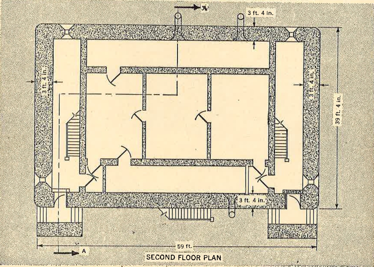 |
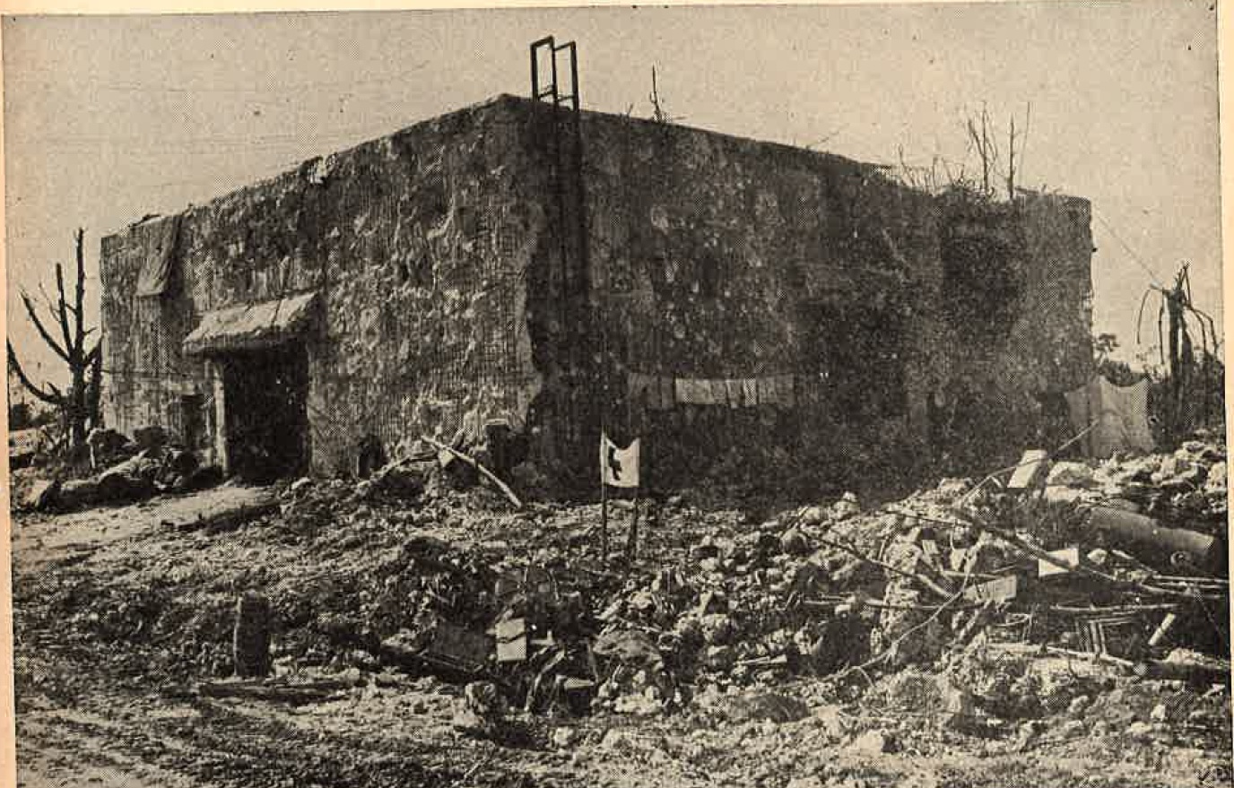
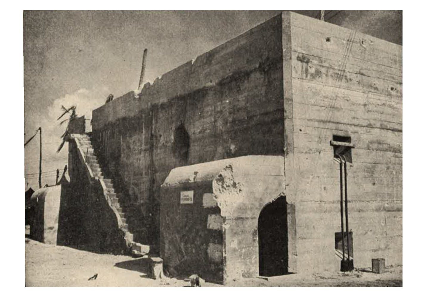
Figure 35. Concrete fuel storage building. In this design which is 57 feet long, 52 feet wide, and 21 feet high, four interior columns support a 3 foot thick roof slab. one foot of sand is added to the flat roof below the paprapet as additional protection. Vents are set in the side walls, and concrete overhangs protect the single side wall windows from aerial bombing. |
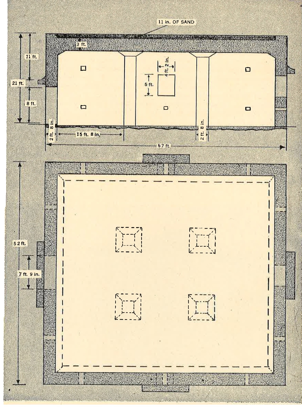
Figure 36. Details of concrete fuel storage building. |
d. Open emplacements. Antiaircraft guns, dual purpose weapons, and many of the Japanese coast defense guns are found in open emplacements. Materials of construction vary according to the permanence of teh position and the time and materials available. Larger guns, because of their weight, are usually emplaced on concrete or metal bases.
The general shape of most of the emplacements is a circle or semicircle, varying in diameter accordng to the size of the gun. Many of the smaller guns have square, octagonal, or elliptical emplacements.
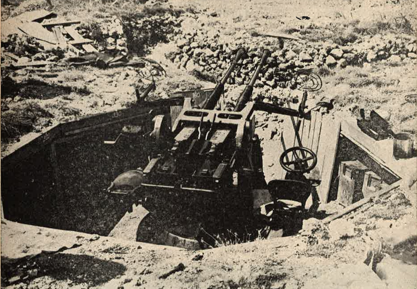
Figure 37. Emplacement for twin mount 25-mm automatic antiaircraft gun. |
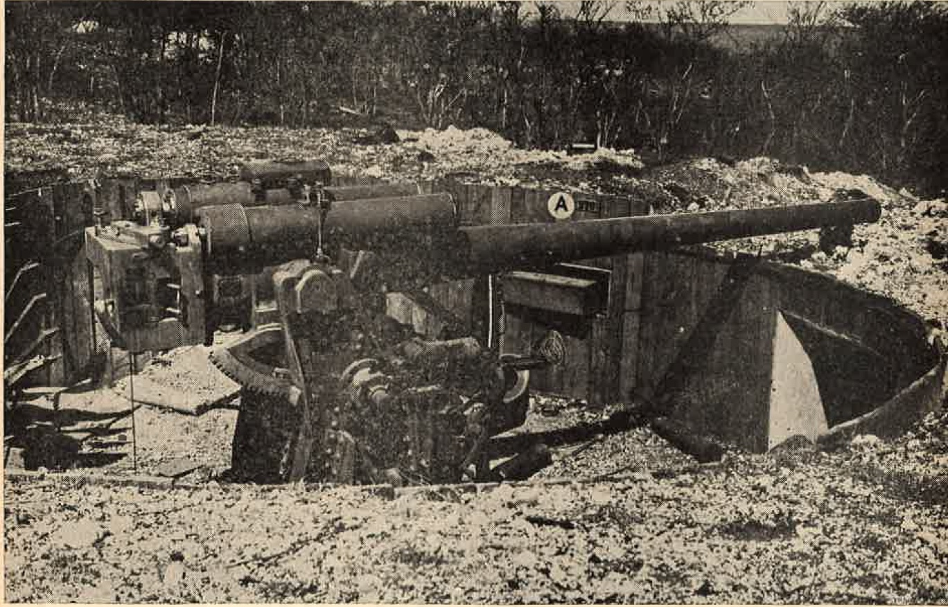
Figure 38. 120-mm dual purpose gun emplacement. |
The 13.2-mm, 20-mm, 25-mm, and 40-mm automatic antiaircraft weapons have been found in both single and double walled emplacements usually consisting of earth, or in wooden-and-earth revetments. Heavy antiaircraft, dual purpose, and coast defense guns may be found in either log-and-earth or reinforced concrete emplacements.
Sandbags and oil drums filled with sand are also used for revetments; sod covering may be added for camouflage purposes.
|
A circular emplacement, 21 1/2 feet in diameter and set 5 1/2 feet below ground level, is used for the 120-mm dual purpose gun.
The sides are revetted with lumber 1 1/2 inches thick.
Precast concrete ammunition chambers with 8-inch walls are located with each gun, and provide storage for 60 rounds of ammunition. Twin mount, 127-mm dual purpose guns found at Betio and Kwajalein were set in circular reinforced concrete emplacements which are banked with sand and coral. Empty emplacements were found at Saipan and Peleliu. Sometimes these emplacements were constructed on a mounded fill, 12 to 15 feet above the natural ground level, to gve guns elevation and command, and to furnish an operating and storage chamber beneath the gun mount. Ten ready boxes for ammunition were built at regular intervals into the circular emplacement wall. A similar emplacement is used for the 14-cm coast defense gun. A few 200-mm heavy coast defense guns have been identified, mounted in tandem. The two guns are placed in a single concrete emplacement containing ready ammunition rooms and a plotting room. A 12-inch steel ammunition trough, approximately 2 feet high, almost completely encircles each gun. In figure 40 the storage can be seen under the housing. A comparison of the size and shape of revetments for the different guns can be obtained from the chart below. |
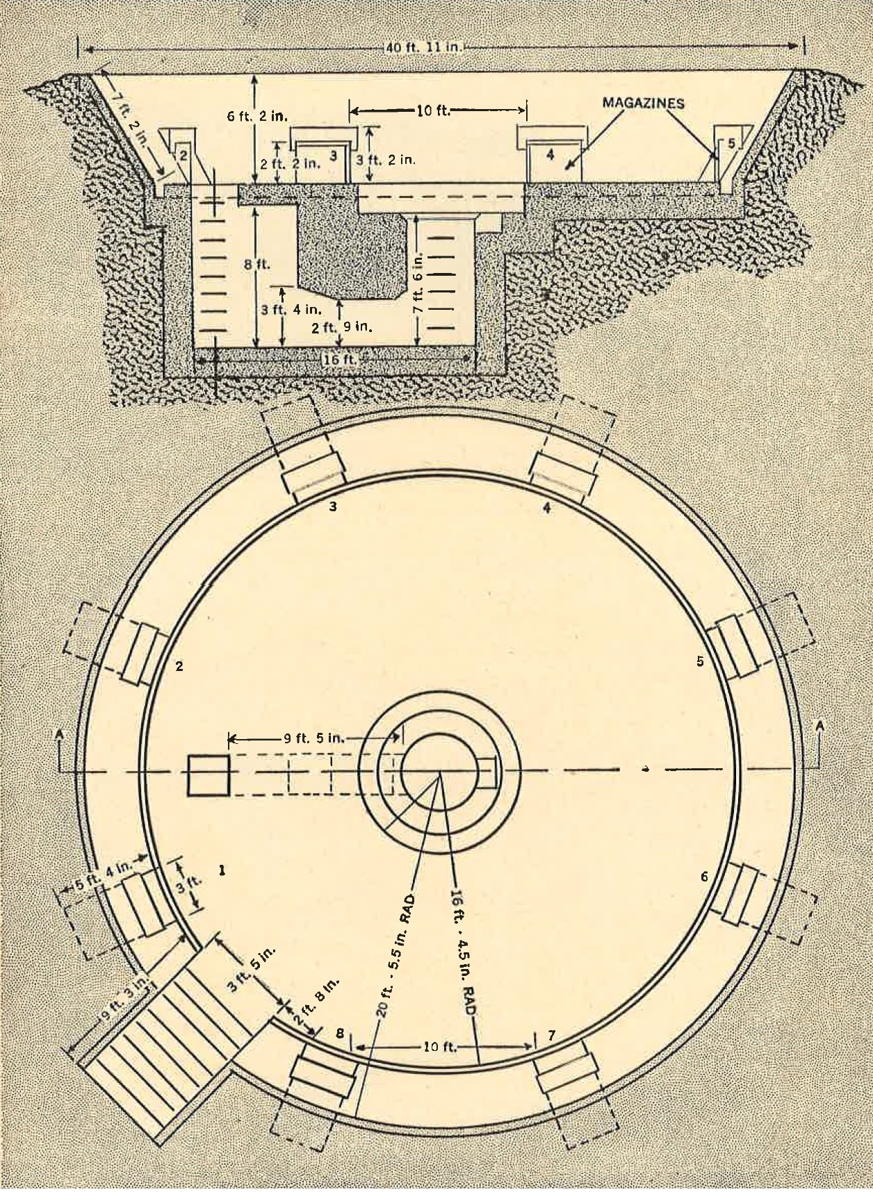
Figure 39. Concrete emplacement for twin mount 127-mm dual purpose gun. |
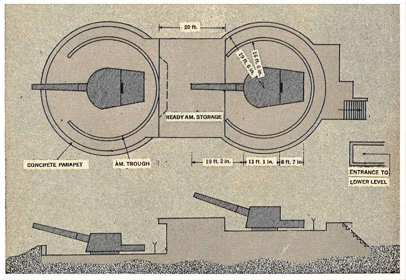
Figure 41. Details of emplacement for 200-mm coast defense gun. |
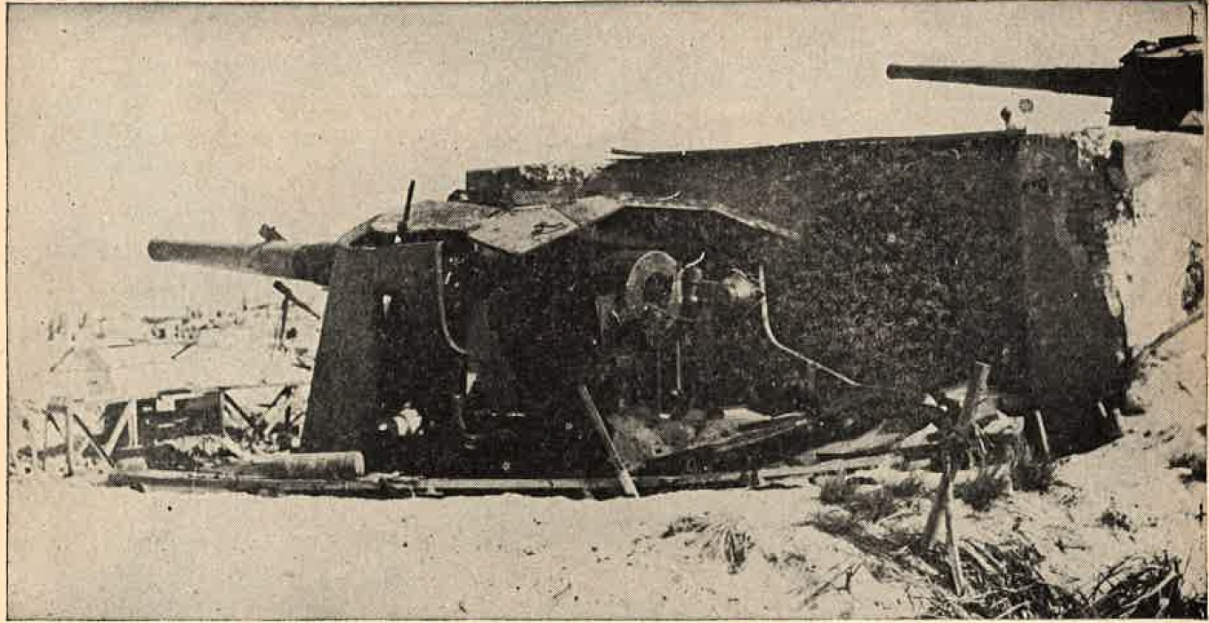
Figure 40. Emplacement for 200-mm coast defense gun. |
COMPARISON CHART OF SIZE AND SHAPE OF GUN REVETMENTS
| Num | Caliber (mm) | Type | Revetment size (inner diameter) (feet) |
Revetment shape |
| 1 | 13.2 | AA | 7-10 (Single) 9-12 (Twin) |
Round (sometimes double wall), square, octagonal, or elliptical. Covered emplacements when used for ground fire. |
| 2 | 20 | AA, AT | 10-16 | Round or square. Covered emplacements for AT. |
| 3 | 25 | AA | 8-10 (Single) 10-16 (Twin) 10-16 (Triple) |
Round. May be single or double wall. |
| 4 | 40 | AA | 10-16 | Round. May ve single or double wall. |
| 5 | 75 | AA | 18-22 | Round or pentagonal. |
| 6 | 76.2 | AA, CD | 14-20 | Round or pentagonal. Square covered emplacements for CD |
| 7 | 105 | AA | 23-25 | Round. |
| 8 | 120 | AA, CD | 20-28 | Round. Square covered emplacements for CD. |
| 9 | 127 | AA, CD | 33-38 | Round. |
| 10 | 140 | CD | 34-37 | Round. |
| 11 | 150 | CD | 26-30 | Round. Also covered emplacements. |
| 12 | 200 | CD | 37-39 | Round. |
| 13 | 200 Howitzer | CD | 10-25 | Round. Also rectangular covered emplacements. |
| 14 | 240 | CD | ? | Semicircular. |
4. CAVES.
|
a. General. It is well known that the Japanese exploit to the limit both natural and artificial caves. Excellent
examples of this have been found at Wakde, Biak, Saipan, Guam, Peleliu, Angaur, Luzon, Iwo Jima, and Okinawa where
cave fortifications were employed extensively.
The Japanese have designed their caves for a double purpose in enarly all cases. First, they have a specific use as quarters, storage, personnel shelters, aid stations and hospitals, defensive positions, observation posts, and command posts. Secondly, they are employed as a final defensive entrenchment. As the Japanese are pushed back, they withdraw into the caves, previously stocked with food and ammunition, and stay there until blasted out. Organized cave defense, as found on various islands from Bial to Iwo, presented a new and |
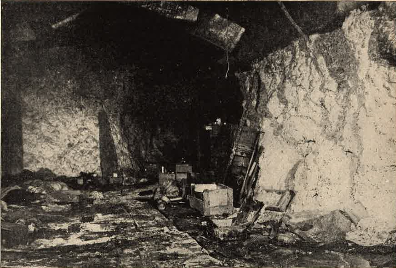
Figure 42. Interior of personnel cave on Peleliu. |
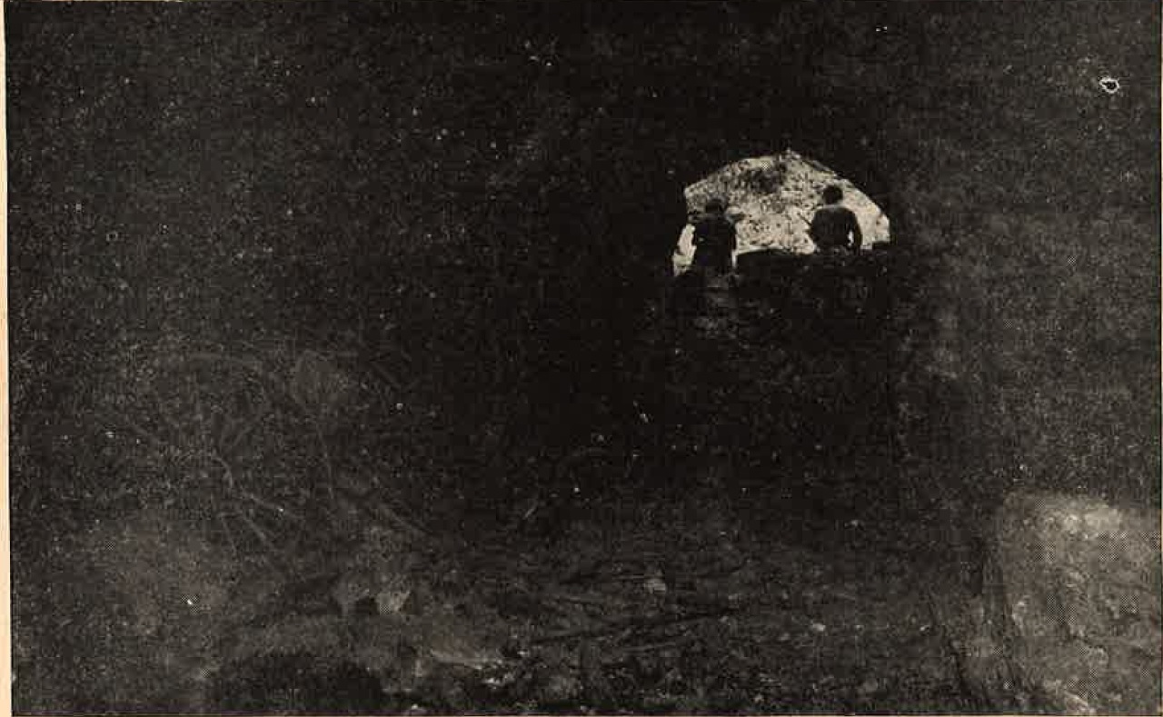
Figure 43. Defensive type cave for 75-mm mountain gun. |
very formidable problem to the U.S. attacking forces. By their very nature almost impregnable, the caves in many
cases are virtually inaccesible and very difficult to detect, needing little of not camouflage other than
provided by nature.
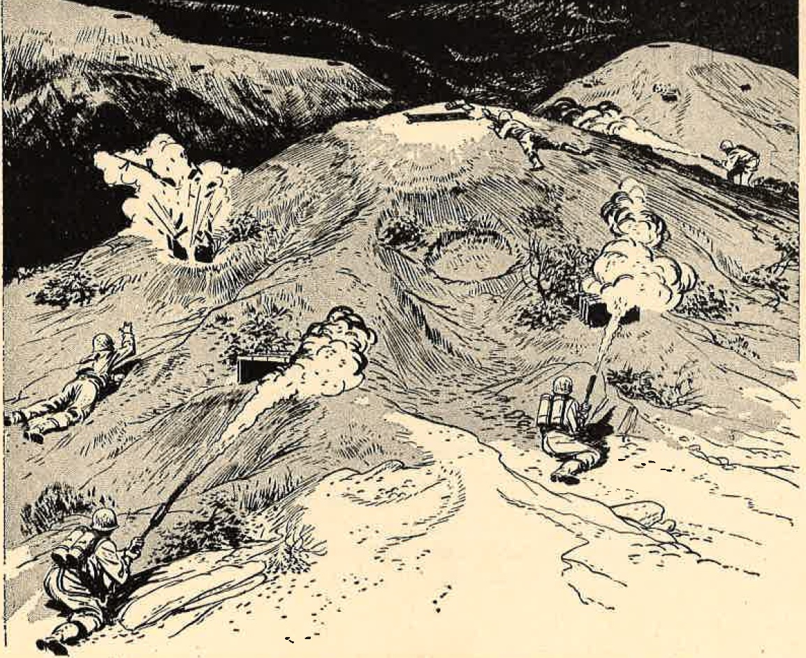
All of the caves are honeycombed with tunnels and passages. They are supported by pillboxes and field fortifications. The problem of reducing caves involves reducing the mutually supporting positions defending the mouths of the caves and destroying the enemy taking refuge in the innermost recesses. Because of the great distance, and many winding tunnels, flame throwers are not effective against caves unless they can be brought within close range. Demolition charges are highly successful, but it has been found that each type of cave has to be dealt with individually. A good example of this |
was found at Angaur where the fortifications consisted of a series of connected compartments extending ro a depth of 50 or 60 feet underground. The compartments, each about 10 feet square, were staggered and constructed on successive levels, somewhat like a staircase.
Flame throwers and demolition charges neutrakized the upper chambers, but had no efect on the lower levels. They were finally reduced by pouring gasoline into the entrance and igniting it.
 |
 |
b. description of caves.
|
(1) General.
The majority of caves used by the Japanese are natural formations, enlarged through the years by water seepage. In many of them the Jaoanese have improved on anture by cutting firing embrasures, by opening secondary entrances and escape routes, by enlarging the interiors, and by reinforcing the walls and ceiling with a mixture of rock and cement. Entrances are narrow and in many cases multiples,so that personnel inside will not be trapped if one entrance is blocked. Blast walls constructed of coral, or barrels filled with rocks and sand, or concrete sometimes are built in front of the entrances. (2) Peleliu. In several large caves up to 500 feet in length, the rooms and passageways were construted at staggered levels. |
 |
 |
One, quartering at least 200 men, had nine wooden decks, with about 4 feet of head space between decks. Many were
equipped with electric lights, fans, ventialtion systems, and cookling facilities. Empty oil druns were used tp
collect water dripping from the stalactites.
Command posts 30 feet below the entrance level contained complete communication facilities, radio, and electric lights. Some of the caves had been constructed primarily as defensive positions. These were mostly on the lower slopes and housed 75-mm mountain guns that could be put into firing position at the cave's mouth. Rooms for ammunition and quarters were cut in all of these. Natural caves at the peaks were used as observation posts and were provided with telephone communications. |
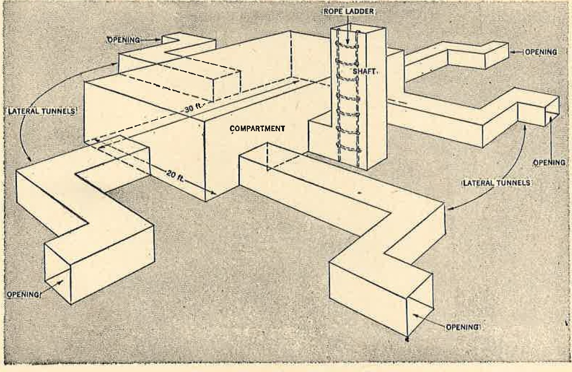
(3) Luzon.
Cave compartments, measuring 20 by 30 feet, were dug out of the inside of hills. Each such compartment, housing about 25 men, was connected to the outside surface by a vertical shaft and four or five lateral tunnels.
The vertical shaft, large enough for a man to climb down, was usually about 10 feet deep with a ropw ladder down one side. The bottom of the shaft connected with the compartment. Each of the lateral tunnels led to the surface on the side of the hill, and probably sloped downward to facilitate drainage of water from the compartment and to prevent the entrance of surface water.
Each tunnel had two sharp turns near the entrance to prevent shell fragments and direct fire missiles from entering the compartment. Machine guns were set up tp fire from the tunnel entrances, and when hostile fire directed at them became too intense, the Japanese withrew into the tunnel or compartment. The positions were located with tunnel entrances close enough together to provide mutually supporting fire.
(4) Iwo Jima
caves on this island were used extensively for gun emplacements, as well as for other purposes. Artillery weapons were emplaced in them, and the openings, except for a small embrasure, then were sealed with reinforced concrete. This made the task of detecting and neutralizing them extremely difficult.
As an indication of the density of caves on Iwo, approximately 100 caves, each 30 to 40 feet deep, were neutralized in an area measuring 400 by 500 yards. Mount Suribachi contained 5 man caves on three levels, all connected by underground passages.
The largest caves was capable of housing 300 men and had five openings. Connecting installations were so extensive and snipers so numerous that it was necessary to destroy most of the installations by demolition after the capture of Suribachi.
(5) Okinawa.
Cave defenses on Okinawa were developed to an even higher degree of efficiency. Most of these caves which varied in size, were connected to interior tunnels which extend through the ridges from the front to back. The trend seemed to be to use different parts of each cave as personnel shelters, supply dumps, and weapons emplacements, although there were separate caves used for special purposes such as aid stations, hospitals, and storage.
The size of the cave entrances ranged from small openings 2 feet square to others large enough for two horses to enter abreast. Usually antitank guns and direct fire weapons were placed in caves at lower levels, and the automatic weapons and riflemen would be emplaced in caves above them. The emplacements for artillery pieces had sliding iron doors to protect the guns when not being fired.
These entrances were so constructed that the guns could be rolled to the entrance, fire a few rounds, and then be pulled back inside teh cave to escape counterbattery fire.
It seems safe to assume that wherever the terrain permits, the Japanese will continue to use caves as part of their fortification system, and the trend at the present time is to dig deeper and deeper underground.
5. JAPANESE FORTIFICATIONS IN NORTH CHINA.
a. General.
The fortifications erected by the Japanese in north China vary considerably from the usual modern permanent defense works. They are best generally described as being medieval in appearance, closely resembling forts and block houses of the European middle ages. They are designed principally to protect the main lines of communication against Chinese guerrilla troops, and probably would not whitstand modern artillery fire.
Strongholds or forts are constructed at key points. Each type of fort contains a tower from two to four stories high, encircled either by a moat, a wall, and barbed wire entanglements, or by a combination of these.
|
Field defenses are set up around the forts. Tunnels, connecting forts with each other and with their field defenses, are
used for escape, for counter attack at the rear of besieging forces, or for re-entry into and attack upon captured forts.
b. Mountain forts. (1) Strongholds. Mountain strongholds are usually constructed on some high point dominating a major line of communications and conveniently near a village where part of the garrison may live. Construction materials are presumably stone, brick, and concrete. Figure 46 illustrating a typical mountain stronghold shows a hexagonal tower about 18 feet high with a 10 foot sub-story. It is 15 feet in diameter and has walls 3 feet thick. There are loopholes in each wall at two levels. Screening walls divide the interior |
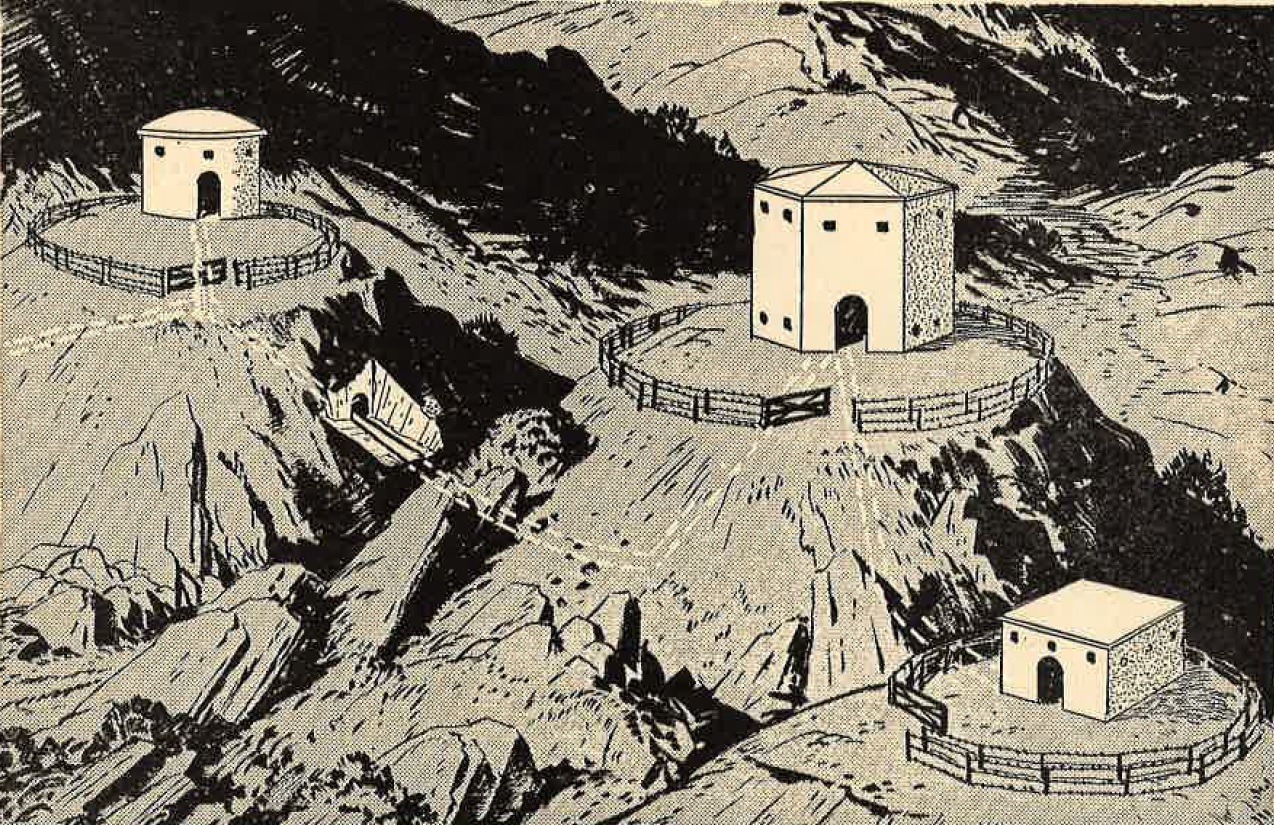
Figure 46. Japanese stronghold in the mountains. |
into compartments to protect the defenders from the explosion of grenades thrown into the loopholes. There is a single doorway, but tunnels connect the stronghold and two flanking pillboxes. Barbed wire entanglements circle each of the structures.
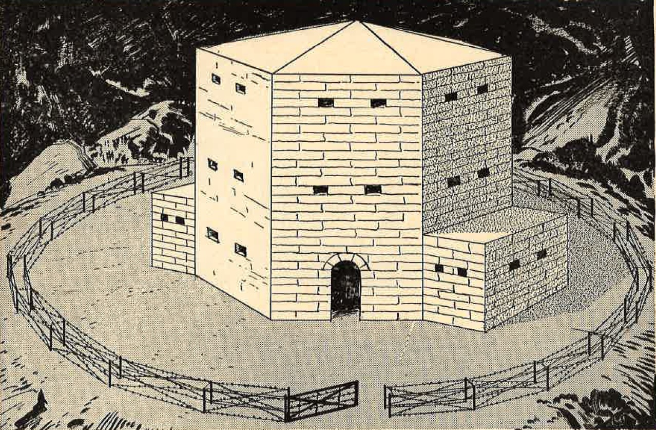
Figure 47. Japanese block house in the mountains. |
(2) Blockhouses.
Blockhouses are placed near important villages along the railways and motor highways. They are usually circular or hexagonal in shape. The type illustrated is hexagonal, made of stone and brick, in three stories, and about 26 feet high. It is 20 feet in diameter and has walls 4 feet thick. There are loopholes in each side on all stories, and interior screening walls are provided. It is surrounded by a barbed wire entanglement. The usual garrison for one of these blockhuoses is approximately 20 men. c. Forts on the plains. (1) Strongholds. On the plains, strongholds are built in towns, and at strategic places on railways and main highways. Definite information on construction materials is not available, but brick and |
These towers are 7 feet in diameter, and contain loopholes. In the center of the stronghold is a circular tower 30 feet high and 15 feet in diameter. Tunnels connect the living quarters of the Japanese garrison with the central tower, and with the towers at the corners.
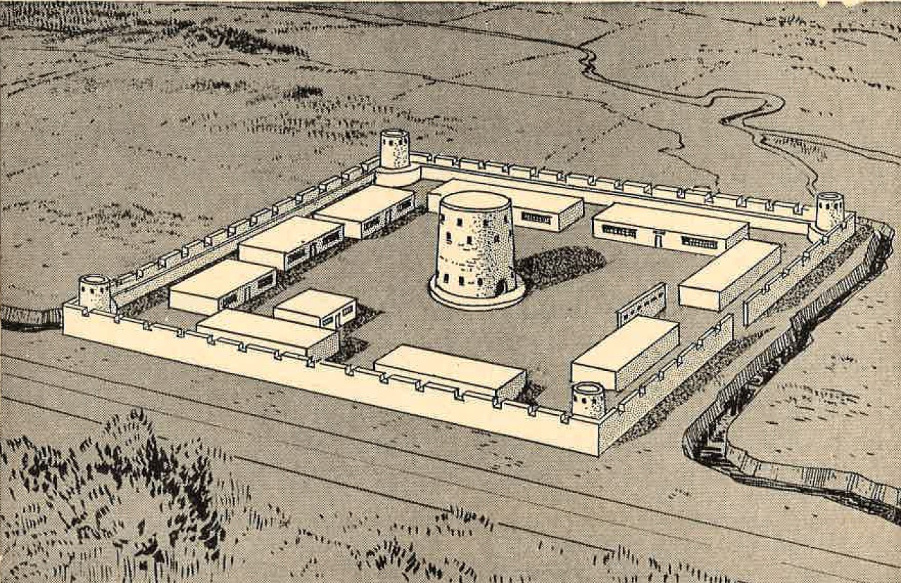
Figure 48. Japanese fort on the plains. |
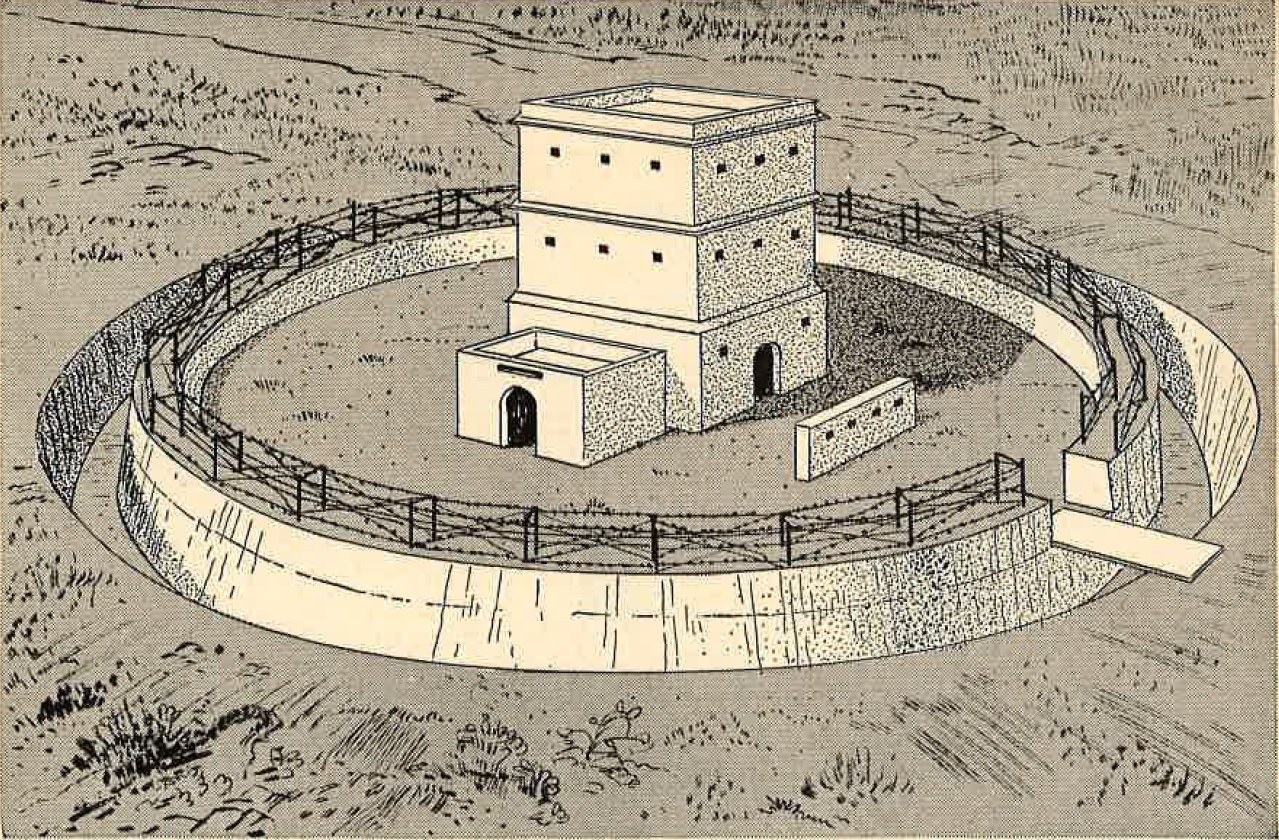
Figure 49. Japanese blockhouse on the plains. |
(2) Blockhouses.
These are placed about 1 mile apart along the highways and railways. There are several different types, but each has a moat with a drawbridge, a wall, barbed wire entanglements, and a tower. The towers vary in height from 22 to 31 feet. Five to ten men armed with one light machine gun and one grenade discharger guard each blockhouse.
SECTION III - FIELD FORTIFICATIONS.
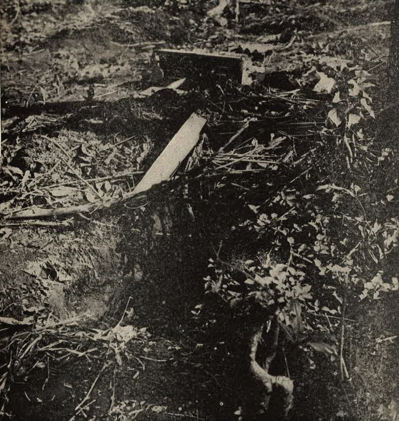
Figure 50. Typical Japanese foxhole in Leyte. |
1. GENERAL.
Field fortifications are works of a temporary nature, frequently constructed hastily, sometimes under fire. They include fox holes, light and heavy machine gun emplacements, communication trenches, dugouts, observation posts, and certain types of obstacles, primarily barbed wire and mine fields. In contrast to permanent fortifications, which are entirely defensive in character, field fortifications may be used in offensive operations during temporarily halts, or to help hold a newly won objective. Field works, in the form of communication trenches, fox holes, and weapons emplacements, are used alone, or with permanent installations to provide positions from which counterattacks can be launched, and close-in protection for the permanent installations. The Japanese have established standard plans for weapons emplacements, communication trenches, shelters, observation posts, and dugouts. Natural terrain features, strengthened or revised as necessary, are utilized to the fullest extent. Caved, buildings, and other structures are extensively and skillfully used as shelters and weapons emplacements. Field fortifications are ordinarily constructed by the troops that are to occupy the position. The Japanese soldier is an expert at diggin in quickly and effectively, where the terrain permits. When an excavation is not feasible because of soil conditions or ground water, a parapet is built up of logs, stumps or sandbags; or existing objects such as walls may be used. Japanese plans call for the initial construction of prone or kneeling fox holes, and of shallow weapons emplacements. |
Then, as time and personnel are available, the position is developed to include standing fox holes, covered weapons emplacements, observation posts, and shelters, all of which are connected by communication trenches and protected by antipersonnel and antivehicle obstacles.
2. WEAPONS EMPLACEMENT.
|
a. General.
The primary purpose of the weapons emplacement is to increase the effectiveness of the weapons by protecting both them and the operating personnel from enemy fire, at the same time permitting the weapons to accomplish their mission. b. Fox holes. The basic weapons emplacement is the fox hole. Three standard individual type profiles are specified; prone, kneeling, and standing, usually varying in depth from 2 to 5 feet. The spoil is piled in front as aparapet and generally is carefully camouflaged. Iy is common practice to place a light cover over the hole for further concealment. The two man fox hole and slit trench are elaborations of the fox hole. Angles and ammunition niches may be added to slit trenches if considered necessary. |
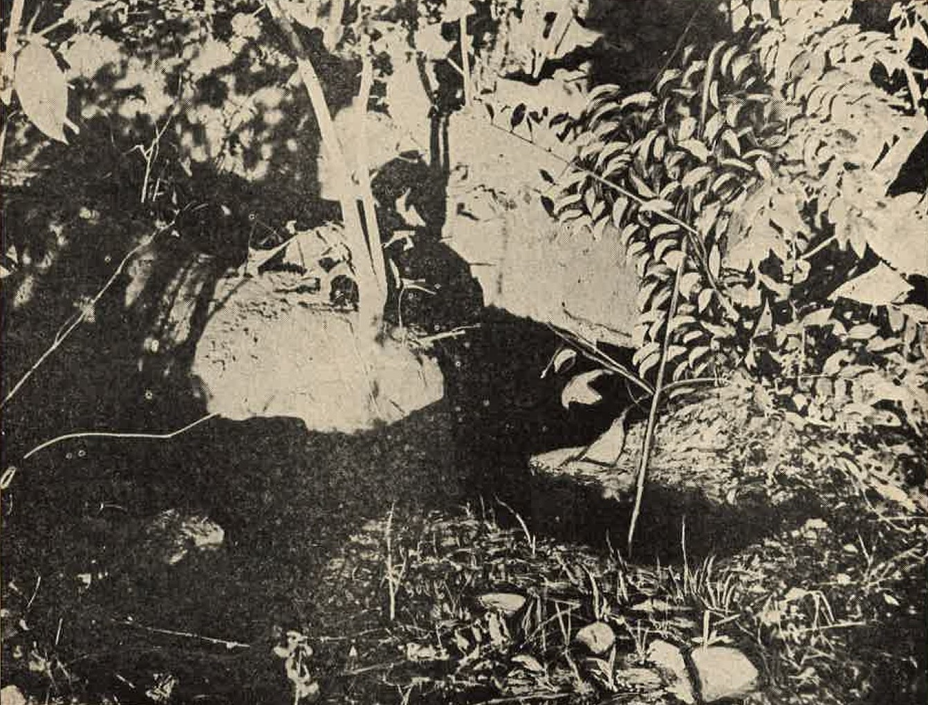
Figure 51. L-shaped slit trench with ammunition niches. |
 |
 |
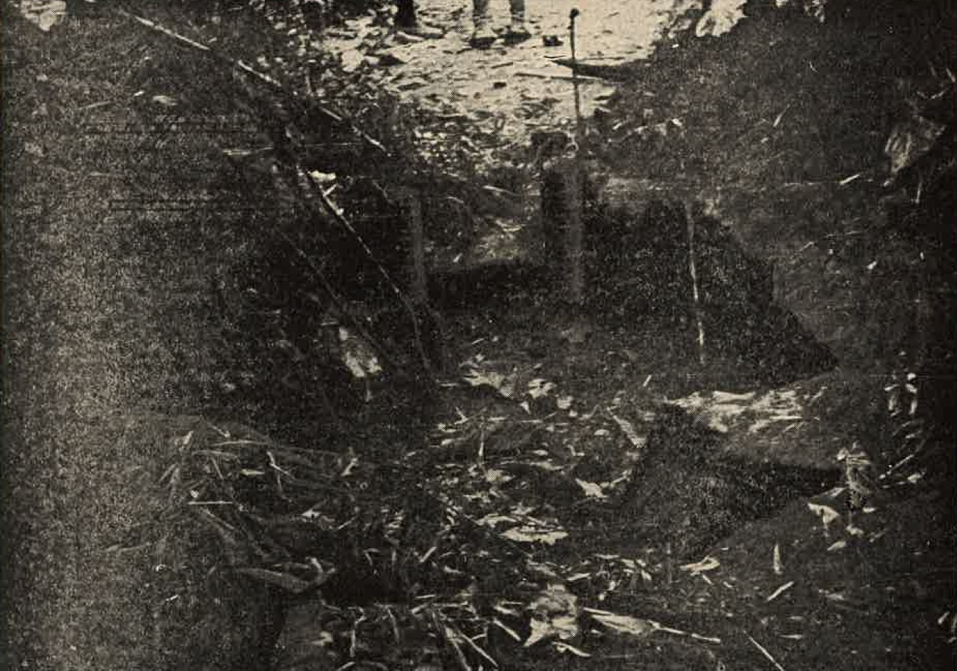
Figure 53. 37-mm antitank gun position in Burma. |
c. Light machine gun emplacements.
Emplacements for the light machine gun and grenade discharger are similar to two-man standing type fox holes, except that the parapet is built from 3 to 4 feet in front of the excavation to allow space for the weapon. d. Heavy machine gun emplacements. The heavy machine gun emplacement is about 9 feet wide, to accommodate the two or three man gun crew. According to the Japanese plan, the excavation is constructed roughly in the shape of an U around the sides and raer of the weapon. The sides of the excavation are revetted when necessary. In oractice, the position is usually provided with a light, camouflaged, log-and-earth cover, about 2 1/2 feet thick, with an embrasure for the gun. The emplacement is often provided with ammunition niches in teh sides. The position is about 2 1/2 feet deep. e. Infantry gun emplacements. The standard open position for an infantry gun us a relatively shallow emplacement, resembling a cross in plan. The excavation is about 3 feet deep, with the spoil piled around the front and sides, providing about 5 1/2 feet of cover for the gun and crew. At the base of the cross, the excavation is sloped to allow the gun to br wheeled into the position. |
The smaller side wings are for ammunition. the entire emplacement generally is carefully camouflaged. The Japanese commonly provide a light timber-and-earthcover for the field gun emplacements. This increases protection and facilitates camouflage.
3. DUGOUT (SHELTERS).
Dugouts, or shelters, are installations designed to provide protection for personnel, weapons, or supplies. They usually are not intended for use as fire positions. They are designed as light, medium, or heavy depending upon the amount of protection provided light shelters are designed to provide protection against shell fragments and instantaneously fuzed light and medium artillery shells. They are provided with 1 to 6 feet of earth cover or the equivalent.
Medium dugouts, with about 19 feet of earth cover or its equivalent, are designed to resist time shells of caliber up to the 120-mm howitzer. Heavy dugouts, which have 32 feet or more of earth cover or its equivalent, can resist larger caliber artillery shells.
Personnel shelters hold from three to six men and may include bunks for sleeping. Shelters for heavy machine guns and field guns are located near the gun emplacements, and are so constructed that the guns can be moved quickly from the sheltersto the firing positions. Medium and heavy dugouts are often provided with elaborate devices for ventilation, gas proofing, illumination, heating, and drainage.
4. OBSERVATION POSTS.
Observation posts are positions from which the enemy movements and situation can be advantageously observed, protection to perosnnel is secondary and is provided only to the extent that it will not interfere with the mission of the post. The Japanese prescribe two kinds of observation posts:
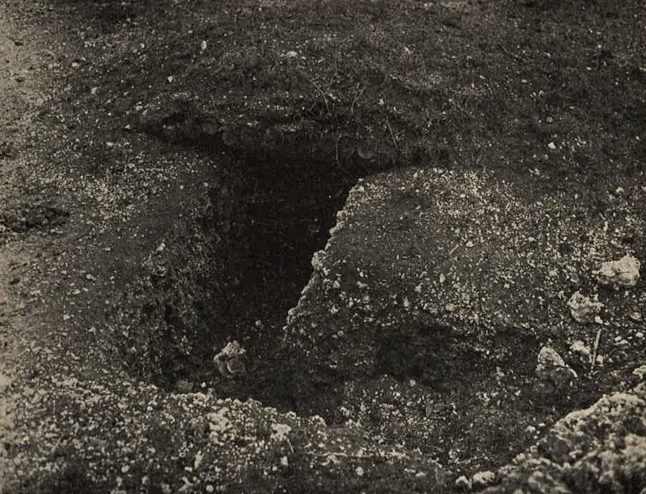
Figure 54. Light personnel dugout. |
(1) for command use and (2) for entries. The sentry posts are built for only one or two men, while command posts are large
enough to accommodate several persons, together with necessary communication and observation equipment.
Depending upon the terrain, an observation post may be a covered dugout with an observation slit, or it may be located in a tree or on an imporovised tower. The Japanese also utilize tall buildings. |
SECTION IV - OBSTACLES.
1. GENERAL.
The employment of obstacles by the Japanese is based generally on the same principles that govern their use by the U.S. Army. For example, artificial obstacles are used to increase the defensive strength of a position by supplementing the natural obstacles. The use of covering fire develops the maximum effectiveness of both artificial and natural obstacles. These are intended only to impede or temporarily to stop enemy vehicles and hold them under the fire of covering weapons; they may, merely by their presence, influence the enemy to attack elsewhere.
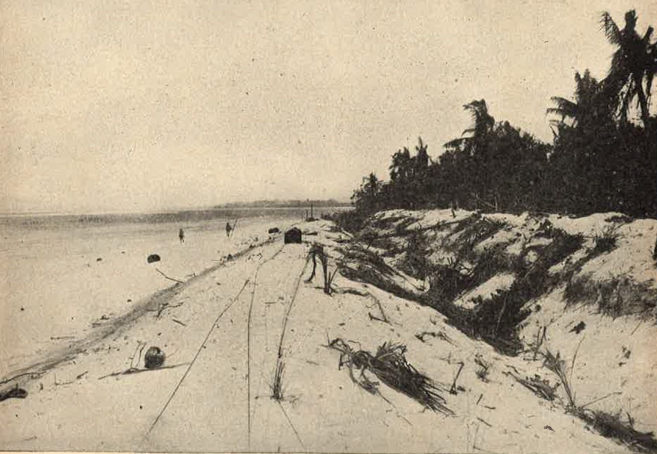
Figure 55. Triangular antitank ditch on beach. |
The outstanding characteristic of Japanese obstacles is that they are constructed largely of materials available locally,
or are improvised from weapons or equipment intended primarily for other purposes.
Cement has been scarce in some areas, and its use by the Japanese in fortifications generally has been restricted largely to pillboxes and emplacements, although cement and steel are used in limited quantities in the construction of a few very simple obstacles. With one possible exception of antitank and antiboat mines, the Japanese have used no manufactured obstacles such as the German pre-fabricated steel types. To facilitate presentation, obstacles are divided into three types: antitank, underwater, and |
|
antipersonnel. This
division, however, does not infer that there is a sharp distribution in the functions of the three types, as they are
often used interchangeably by the Japanese.
2. ANTITANK OBSTACLES. a. General. It is common practice for the Japanese to use several different types of antitank obstacles in a single defensive position. It should be remembered that only the general form and nature of the obstacles will remain constant. The materials used for their construction, as well as their size and method of construction, will vary with the nature of the terrain and with the equipment of the opposing forces. Any of the antitank obstacles can be and are used either as road blocks or as continuous barriers. They may also be used as inland or as beach obstacles. b. Ditches. The antitank ditch, one of the most common Japanese antitank obstacles, has been used on nearly all of the defended Pacific islands, both as a beach obstacle and as an inland tank barrier. Ditches also have been used in Burma where one ditch was reported to be over a mile long. In some places, ditches are divided into cells or sections by earth walls, a foot or two wide, left at intervals along the ditches. |
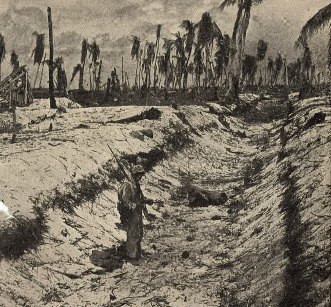
Figure 56. Trapezoid antitank ditch. |
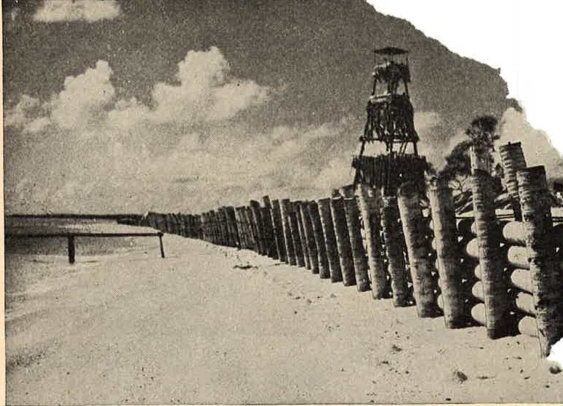
Figure 57. Log wall antitank obstacle. |
Ditches thus far encountered in the Pacific Theater vary from 10 to 20 feet in width and from 5 to 10 feet in depth. The
most common cross sections are triangular and trapezoidal (Figure 55 and 56).
The spoil is usually piled on the defender's side of the ditch, thereby increasing its effective depth. The ditch may be camouflaged with palm fronds or other material, and sometimes the spoil ios removed or scattered to facilitate concealment. c. Log barricade. The log barricade is a commonly used antitank obstacle. It has a number of variations. One of the simplest types, consisting of horizontal logs attached to trees 3 or 4 feet above the ground, is used in woods or where there are enough heavy trees. A contrasting type consists of a solid wall of logs placed horizontally between vertical posts. A more common variation , illustrted in Figure 58, is a fence like structure consisting of two or three horizontal logs attached to braced vertical posts. |
|
This barricade is about 5 feet high and consists of native timber logs at least 1 foot in diameter. This type of barricade
is also used as a beach and as an underwater obstacle.
d. Posts. Post obstacles consist of a field, or series, of timber or concrete posts. Timber posts are most common, and the Japanese state that they should be of oak and at least 12 inches in diameter. If palm logs are used, they must be braced. palm log posts have been strenthened by fastening three posts together in a clover leaf. The posts, from 5 to 10 feet long, are placed with an average of about two-thirds of their length in the ground. Standard Japanese patterns call for one, two, or three rows of posts (Figure 59). Instruction for the construction and use of concrete posts obstacles have been issued by the Japanese, |
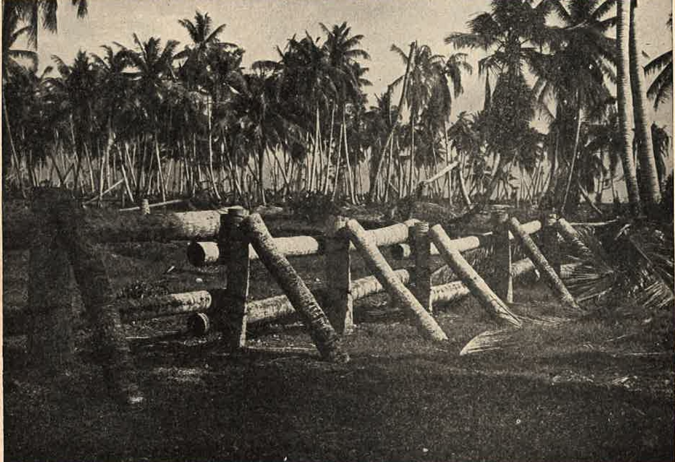
Figure 58. Log barricade antitank obstacle. |
|
Though there are no reports that such obstacles have been encountered in the field. Plans prescribe a post 6 to 7 feet long
and about a foot square, with both vertical and horizontal steel reinforcing. Such posts are emplaced with about one third
of their length embedded in concrete bases in one, two, or three rows, with 5 to 7 feet between rows, and with the posts in
each row 6 to 10 feet apart.
Post obstacles are prescribed for use both on land and as underwaterobstacles. Both timber-and-concrete post obstacles may be made more effectively by inclining the posts toward the enemy. Three stumps, 3 to 5 feet high, have been left to serve as antitank obstacles on some Pacific islands. e. Abatis. The abatis is a simple but less effective obstacle. It consists of large trees felled with the tops towrds the enemy so that the branches become intermingled. This obstacle finds it widest use by the Japanese as a road block. Trees along a narrow road can be prepared for demolition and then blown at the last minute. They have been used in this manner in Burma. In a few cases mines or booby traps have been placed in the abatis. Walls. The Japanese have constructed very few solid concrete walls. Wall obstacles have been constructed of native rock held in place with cement. The walls are set at least 4 feet high and are generally backfilled. They are designed to be high enough so that a tank cannot climb over them, and strong enough to resist being overturned or destroyed by gunfire. A wall-type obstacle found on some Pacific islands is constructed of palm tree stumps. The excavated stumps are piled up with the roots toward the enemy, forming a fairly effective obstacle. |
Figure 59. Standard patterns of typical antitank obstacles. |
Figure 60. Methods of placing Type 93 tape measure antitank mines. |
g. Minefields.
(1) General. The Japanese did not start to use minefields effectively until after the battle for Saipan. Prior to that time, their mines generally were poorly sited and inneffectively camouflaged. In subsequent operations, however, in Burma, the Philippines, Iwo Jima, and certain other Pacific islands, minefields have been much more effectively employed . The Japanese have prescribed standard patterns and principles for the use of mines. According to these principles the minus may be laid between other antitank obstacles, in areas that are difficult to cover with firepower, and where the nature of the terrain makes difficult the construction of other obstacles. The minefields must be covered by fire and must be kept under observation. The types of mines most commonly used are discussed very briefly in the following paragraphs. These and other types are discussed in much more detail in Chapter IX". (2) Type 93 mine. This is a disc type metallic mine, containing 2 pounds of explosive, which may be used against vehicles alone or against both vehicles and personnel. It is commonly used in roadblocks, or placed in fields consisting of one or more rows of mines. In soft ground, the mine may be attached to a board to increase the bearing surface. Because of its small charge, this mine cannot always be depended upon to disable a tank. The Japanese sometimes correct this by placing two or three |
|
mines together, or by placing a supplemental charge under the mine (Figure 60).
(3) Yardstick mine. The yardstick mine is a khaki colored, bar-type, metallic antitank mine containing 6 pounds of explosive. It is readily camouflaged and is used effectively in road blocks where it blends with the road surface. Standard patterns prescribed for this type of mine consists of two or more rows with the mines placed parallel to the front, 1.6 feet apart, in such an arrangement as to give complete coverage. (4) Non-metallic mines. The Japanese have two standard non-metallic antitank mines: (a) The Type 3 Model A is a disc-type pottery mine containing 6 1/2 pounds of explsosive. It is both antittank and antipersonnel and can be detonated either by direct pressure or by means |
Figure 61. Aerial bomb abd hemispherical antiboat mine as beach obstacle. |
Figure 62. Antitank mine improvised from naval depth charge. |
of a trip wire. A smaller version of the ceramic type contains 4 1/2 pounds of explosive.
(b) The Type 3, Model B is a square wooden box containing the same quantity of explosive and the same fuzes, and is detonated in the same manner as the Type 3, Model A mine. Both Type 2, model A and Type 3, model B are used in the same patterns as teh Type 93. Their principal advantages over the Type 93 are that they have a larger charge and are more difficult to detect with the usual mine detectors designed to indicate the presence of metallic substances. (5) Antiboat mines. There are two standard Japanese antiboat mines: a hemispherical two-horn type, containing 46 1/2 pounds of explosive; and a conical single horn type, containing 22 to 28 pounds of explosive. These mines were apparently designed for use as beacli obstacles against landing craft. They are used in this role alone and in conjunction with other underwater obstacles. The Japanese also bury antiboat mines on land, with just the horns protruding, as antitank obstacles. In this role they are most commonly used in road blocks, though they have also been used in minefields. (6) Aerial bombs. Aerial bombs have often been employed as antitank mines. several different size bombs are used, including the 63 kilogram (140-pound), 130 kilogram (285 pound), and 250 kilogram (550 pound). |
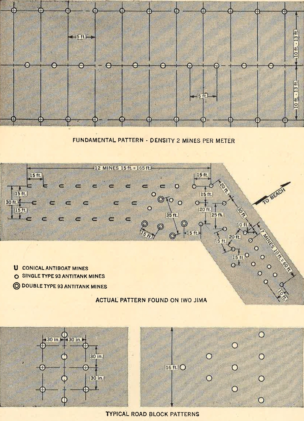
Figure 63. Japanese minefield patterns. |
the bomb, equipped with an instantaneous impact type nose fuze, is buried vertically, with the fuze up and level with the
surface of the ground.
Aerial bombs are used in road blocks, as obstacles on abandoned airfield runways, and in minefields across open country. They have also been employed as beach obstacles, and may be set in the same field with other type mines. (7) Depth charge. Another improvised type of antitank mine consists of a naval depth charge buried on the ground, with a standard antitank mine or a specially arranged charge placed on top as a primer. These have been used in the Philippines as road blocks. (8) Remote controlled mines. In operations in the Philippines and Burma, controlled antitank mines have been encountered. The mines, |
|
standard, or improvised , are placed as road blocks or as minefields off the road, and are exploded electrically or mechanically
from an observation post 50 to 300 yards away. When the mines are electrically controlled, a wire, either on the surface or
buried, leads from the mine to the observation post.
3. UNDERWATER OBSTACLES a. General. In their numerous experiences in preparing defenses against amphibious operations, the Japanese have developed a number of more or less standard typesof underwater obstacles. As with land obstacles, their general tendency is to employ local materials to the full extent. The following types of underwater obstacles will be discussed: scullies, tetrahedrons, "spiders", cribs, barricades, rock mounds, and mines. |
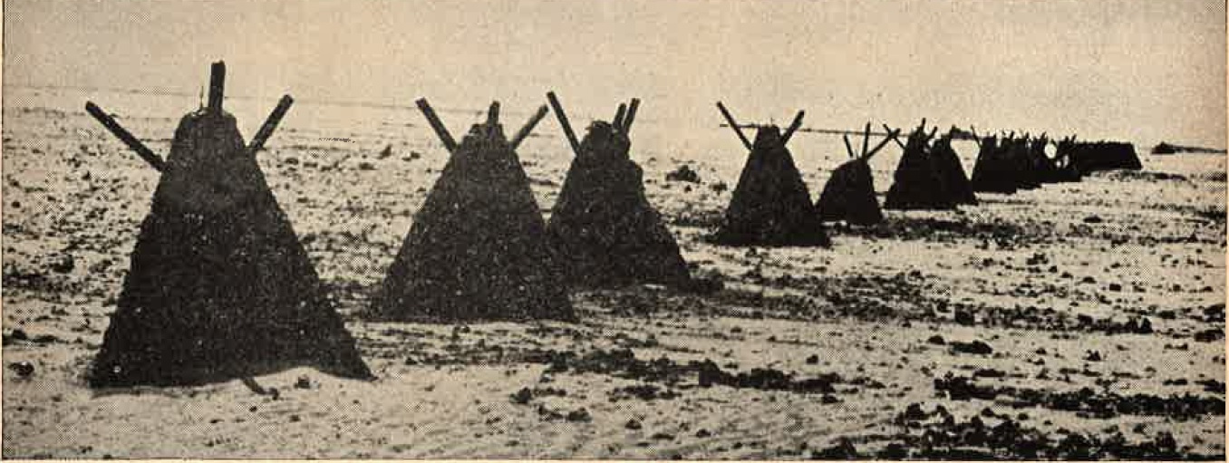
Figure 64. Horned scully underwater obstacles. |
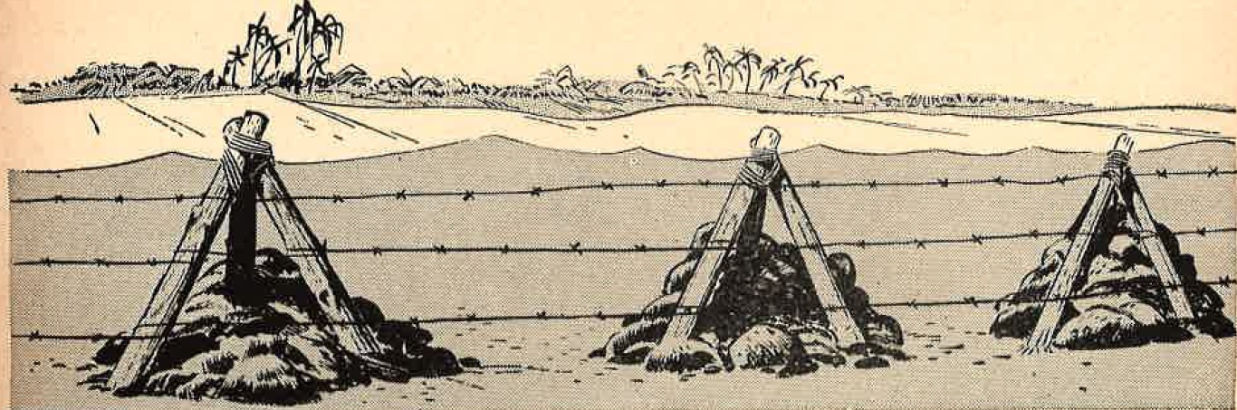
Figure 65. Timber tetrahedrons. |
b. Scullies. The scully, one of the few Japanese concrete obstacles is commonly constructed in two forms. one form is
a frustum of a pyramid, 5 to 6 feet square at the base and 4 to 5 feet high. The other form is a tetrahedron, 3 to 4 feet on
each side.
In both forms, two, three, or four steel rails or structural steel shapes are cast into the concrete, and protrude near the top, at an angle of about 45 degrees to the vertical. The presence of the steel shapes is characteristic of the scully. Scullies are generally placed in one or more rows on the beach, between the high and low water lines; The distance between individual scullies varies from 10 to 20 feet. They are not anchored, but are held in place by their weight. They often are connected by |
|
barbed wire, and sometimes antiboat mines are placed between them.
c. Tetrahedrons and "spiders". The Japanese construct thet tetrahedron obstacle of either concrete or timber. The concrete version, 3 to 4 feet on each edge, is employed in the same manner as scullies. It may also be placed inland as an antitank obstacle. A typical arrangement is shown in Figure 59. The timner tetrahedron generally is similar in shape to concrete type, but is somewhat larger, about 6 to 10 inches in diameter, are generally used for the base, and 12 to 16 inch logs for the uprights. The interior is filled with stones. |
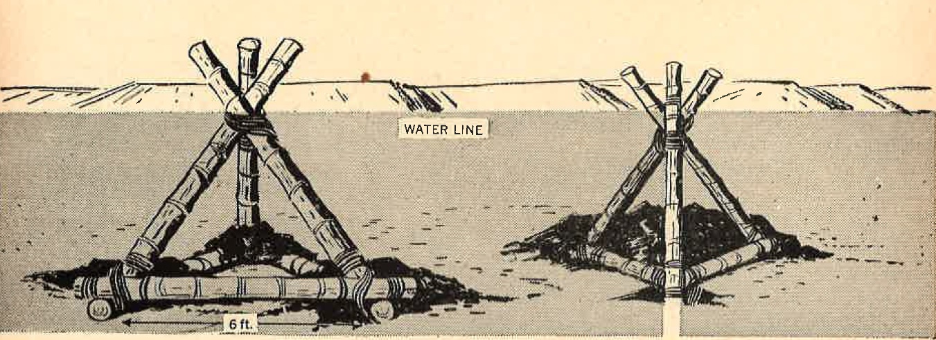
Figure 66. Timber "spiders". |
Figure 67. Rectangular, rock filled, timber crib obstacles. |
A variation of the timber tetrahedron is sometimes called the "spider". The upright pieces extend beyond the apex of the
obstacle, giving it a greater effective height. Tetrahedrons and "spiders", like scullies, are generally placed in one
or more rows between the hihj and low water line.
They may have barbed wire attached to them to form antipersonnel obstacles. d. Timber cribs. Timber cribs filled with rock are common type of Japanese underwater obstacle. Various sizes and shapes have been encountered, most commonly rectangular or triangular, 6 feet or more in height. They have been used in the defenses of the Pacific islands, where apparently such materials as cement and steel for the construction of more permanent types were not available. |
|
Cribs are used in the same manner as tetrahedrons or scullies.
e. Concrete crib. The Japanese have specified a reinforced concrete crib obstacle, although to date none has been encountered. This type consists of an open, box like, reinforced, concrete frame, about 7 feet square and about 5 feet high, which may be filled with rocks. These cribs would be placed about 6 feet apart in one or more rows, probably as an underwater obstacle. f. Rock mounds. One of the simplest of teh Japanese underwater obstacles is a rock mound of coral or other rock, either piled carefully in the form of cubes, or heaped in a mound of no specal shape. The mounds are 4 to 5 feet across and 3 to 4 feet high, and are placed in one or more |
Figure 68. Triangular, rock-filled, timber-crib obstacles. |
Figure 69. Rock-mound obstacles. |
irregular row.
g. Barricades. Variations of the log barricades discussed under antitank obstacles are also used as underwater obstacles. They must be firmly anchored to prevent their shifting as a result of wave action. h. Antiboat mines. Both the hemispherical and conical antiboat mines are used as underwater obstacles. They may be placed in single rows on the beach between the high and low water line, or they may be used with other types of underwater obstacles. |
Figure 70. Employment of hemispherical antiboat mines with scullies.
ANTIPERSONNEL OBSTACLES.
a. General. Antipersonnel obstacles are those designed to stop or impede the movement of personnel. They are not generally effective in stopping or even slowing down vehicles. As with their antitank obstacles, teh Japanese plan to cover antipersonnel obstacles with fire.
Japanese antipersonnel obstacles may be divided generally into three classes: barbed wire, mines, and improvised types.
b. Barbed wire.
(1) General. The Japanese barbed wire obstacles are in general similar to those used by the U.S. Army. In addition to the uses described below, barbed wire is often attached to antitank and underwater obstacles in order to impede personnel.
(2) High wire.
The high wire fence consists of two or more rows of posts, with barbed wire and a combination of barbed and plain wire strung between posts and between rows. Posts are 2 to 4 feet high; rows and the posts in each row are 6 to 10 feet apart.
Figure 71. High wire fence.
(3) Low wire.
The Japanese employ several types of low wire obstacles or snares. One common type consists of several rows of stakes, extending 1 to 1 1/2 feet above the ground, with wire stretched loosely between them. This obstacle will not stop personnel, but it will slow them up and make them better targets for the covering fire. Low wire obstacles are very difficult to see from the air and often cannot be distinguished in aerial photographs.
variations of the low wire obstacles are the several forms of snares. These are simply loops of plain or barbed wire attached at intervals to the ground. Three types of snares are shown in Figure 73.
Figure 72. Low wire as a beach obstacle.
(4) Double apron.
The Japanese use a double apron fence similar to that used by the U.S. Army. The fence is 2 1/2 to 4 feet high, with teh posts 6 to 10 feet apart. The width is 10 to 20 feet. The apron wires may be attached to diagonal wires running from the posts, or the posts may be supported by diagonal wooden braces to which the wires are attached.
Figure 74. Japanese double apron fence.
(5) Cheval-de-frise.
Figure 75. Cheval-de-frise as a beach obstacle. |
The cheval-de-frise, or knife rest, consisting of barbed wire strung on a wooden frame, is primarily an antipersonnel obstacle, though the frame is sometimes constructed of material heavy enough to make it serve as an antivehicle obstacle. It is portable or semiportable depending upon its size and weight. The Japanese use it both inland to block gaps in orther obstacles and as a beach obstacle. |
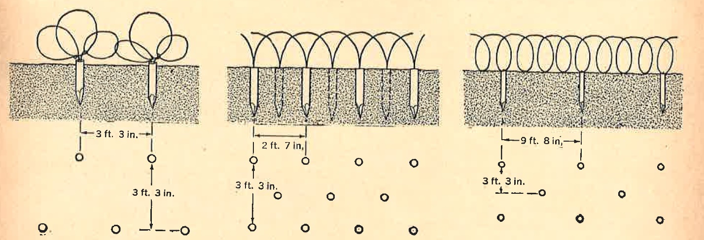
Figure 73. Typical antipersonnel wire snares.
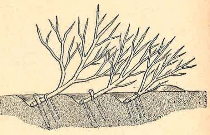
Figure 76. Abatis antipersonnel obsracle.