CHAPTER - 9C2, 9D2 EQUIPMENT

SECTION VIII - WWII JAPANESE ROCKETS.
1. GENERAL.
Japanese rocket weapons, although only comparatively recently introduced, are progressing rapidly, and production models are already begining to appear. This progress is being made under the influence of German rocket design and with the assistance of German experiments with rocket weapons. It is this assistance which is enabling the Japanese to bypass some of the stages between initial experiments and the appearance of production models.
The initial rocket weapons recovered were very crudely designed and consisted mainly of improvisations. Typical of such crudity of design are the Type 10 and Type 3 rocket motors, which are used to push a 60-kilogram (132 pound) bomb off a launchign ramp and so give it the initial impulse necessary to continue its flight. A furthwe development of this weapon, and representative of improvisation stage, is the 30-cm rocket, which consists of a 250-kilogram bomb with tha tail assembly replaced by a fin-established rocket motor.
The early types of launchers were eqyually as crude as their projectiles. Those used with the first rocket motors were metal or wooden trough-shaped ramps supported at the forward end by some simple form of bipod.
The first evidence of influence of German rocket design was the appearance of the 20-cm Navy spin-stabilized projectile. Althought this rocket was an improvisation, consisting of a cut down naval shell with a rocket motor attached to the tail, it showed that the Japanese were beginning to conisider the use of spin-stabilization. Further evidence of German influence is shown by the replacement of the original trough-shaped launcher by one of the tube type, the first of its kind to be used by the Japanese.
It is now believed that both this projectile and its launcher were experiments in the development of the 20-cm Army spin-stabilized rockets and the type 4 launcher. This rocket, and even more certainly the launcher, since it is the first launcher to which a type number has been given, appear to be production models and represent the present stage of development of ground rocket weapons.
| It may be expected, therefore, that the Japanese will continue with experiments and production of spin-stabilized rockets, and that projectiles analogous to if not actually identical with those developed by the Germans will appear in the near future. However, development in other classes of rocket weapons, such as antiaircraft and aircraft projectiles, remain in the primitive stages. During the past few months, many reports have been received of air-to-air, air-to-ground, and ground-to-air missiles, a number of which appear to have been rocket assisted. Also, documentary evidence shows Japanese interest in the development of rocket assisted aerial bombs and points to the production of at least one missile of this type. It would seem reasonable, therefore, to expect that in this field, also new types of rocket projectiles will shortly appear. Initial experiments indicate that aircraft projectiles probably prove to be of the conventional, fin-stabilized type launched from under the wings of fighter aircraft. |
Figure 383. WWII Japanese Rocket launcher emplacement on Iwo Jima. |
If German influence prevails, antiaircraft rockets may appear as "parachute and cable" projectiles. Among oher developments which can be expected is an antitank rocket weapon similar to the American bazooka. A recent Japanese radi broadcast stated that projectiles of this type are being produced at a rate of one million per month. Undoubtedly this is a great exaggeration, but it is fairly certain that a weapon of this class is under production. This may prove to be an adaptation of either the German Raketenpanzerbuchse 43 or the American bazooka.
Finally the stage of development may be summed up by the statement that Japanese rocket weapons are only on the brink of large scale development and production, and the future can be expected to show great progress in this field of armament.
2. GROUND-TO-GROUND ROCKETS.
a. General. The following types of ground-to-ground rocket projectiles have been identified; Type 10 19-cm rocket motor;
Type 3 19-cm rocket motor;
20-cm Navy rocket;
20-cm Army rocket;
30-cm special Mark I roclet motor;
45-cm naval rocket;
b. Type 10 19-cm rocket motor.
(1) General.
This weapon used for launching Type 97 60-kilogram land bomb, differs from the conventional type of rocket projectile in that the rocket motor does not form an integral part of the projectile. The motor is separate and serves merely to propel the bomb out of an inclined trough-shaped launcher. It is one of the earlier Japanese rocket weapons and may be considered obsolescent if not obsolete. Although the original bomb with which this rocket motor was used is the Type 97 60-kilogram (132 pound) land bomb, a later version of this motor, the Type 3 is used with both this bomb and the 63-kilogram (138.6 pound) ordinary bomb. It would appear reasonable ro assume, therefore, that any conviniently sized bomb weighing about 60 kilograms could be used.
Figure 391. Single and triple wooden trough launcher for baval 20-cm rocket.
(2) Construction.
The rocket motor is of simple construction and consists of a propellant chamber, a closing plate, and a tail assembly incorporating a single venturi tube. The propellant chamber is filled with three sticks of propellant and is closed at the forward end by a nose cap. The nose cap is drilled centrally to take an electrical igniter which bears against an ignition charge at the forward end of the propellant. A conical wooden spacing block fits over the igniter; four grooves in this block engage the tail fins of the bomb and form the connection between it and teh rocket motor.
Characteristics:
|
(3) Launching. The rocket and bomb are launched from a trough-shaped launcher. The rocket is placed in the launcher, and the leads from the electrical igniter in the nose are connected to a small exploder in the firing position. The bomb is then placed in the launcher and slid to the rear so that the fins engage with the wooden spacer on the nose of the rocket motor. The metal cover of the launcher is then closed, and teh projectile is ready to fire. The elevation of the launcher is controlled by a cable passing from the base plate round the lower ends of the two bipod legs and back to the base plate. A number of eyes on each side section of the cable enables the launcher to be set at different elevations by linking the eyes to hooks on the bipod legs.
(4) Performance According to a Japanese range table this projectile may be fired up to 1,200 meters (1,311.6 yards).
c. Type 3 19-cm (7.41 inch) rocket motor.
(1) General.
This rocket is a lengthened version of the Type 10 19-cm rocket motor and, like the Type 10, it does not form an integral part of the complete projectile, but serves merely to propel the bomb out of a trough-shaped launcher. This motor is used both with the Type 97 60-kilogram land bomb and with the 63-kilogram ordinary bomb.
(2) Construction.
The motor is constructed in the same way as the Type 10 rocket motor and consists basically of the propellant chamber, the closing plate, and a tail assembly which incorporates a single venturi tube. Like the Type 10 rocket motoe. This has an electrical igniter at the nose end and an ignition charge at the forward end of the propellent chamber. The same or a similar wooden spacing block is used to connect the rocket motor to the bomb.
|
Figure 384. Type 10 19-cm rocket motor, with the Type 97 60 Kilogram bomb and launcher. |
(3) Launching.
This rocket motor is launched in the same way as the Type 10 (Figure 384). The rocket motor is placed in the launcher, and the leads from the electrical igniter are connected to the exploder. The bomb is then placed in the launcher and connected to the rocket motor by the wooden spacing block. Like the Type 10, this tocket motor is fired from a concealed position to the flank of the launcher.
Figure 386. View of a Type 3 (1943) 19-cm rocket motor. |
Figure 387. A Type 3 (1943) 19-cm rocket motor after discharge. Showing the motor imbeded in an airstrip. |
(3) Performance.
No details of the performance of this projectile are available. Since the rocket motor is the same as the Type 10 with the exception of the increased length of the propellent chamber, it is probablr that the maximum range is somewhat in excess of that of the Type 10, probably about 1,900 yards.
Figure 385. Type 3 (1943) 19-cm rocket motor in position on a launcher, ready to propel a 63 kilogram bomb.
d. Japanese 20-cm (7.8 Inch) Navy rocket.
(1) General.
This rocket was the first spin-stabilized projectile to be recovered and consists of what appears to be a cut-down 3 inch naval shell to the base of which a rocket motor has been attached. Although and improvisation, this projectile reflects the design of certain German rockets, having the HE filling forward and a propellent compartment to the rear. The thin wall of the warhead and teh scale on the launcher indicate that this projectile has been designed as a short-range weapon (about 2,000 yards), relying for effect upon blast rather than upon fragmentation.
|
(2) Construction. he warhead of the rocket is of normal design and is fitted with a point detonating nose fuze. The rear end of the warhead is closed by a plate threaded externally to fit into the forward end of the rocket motor. The rocket motor is a plain cylinder of the same diameter as the warhead, and threaded intermally at the rear to take a motor base plate has six offset verturi drillings and a central hole to take a percussion igniter. The propellent consists of seven sticks, six of which are located around an identical severnth stick. The sticks make a reasonably tight fit inside the propellent chamber and are held in place by two grids, one at each end of the chamber. The forward grid contains an ignition charge. When the percussion igniter is struck, teh flash passes along the central stick of propellent and initiates the ignition charge, which in turn sets off the propellent charge. |
|
Figure 393. Tube-type 20-cm Navy rocket launcher. |
Figure 392. Tube-type 20-cm Navy rocket launcher. |
| | |
Figure 390. 20-cm Navy rocket, wooden trough launcher. |
Figure 389. 20-cm Navy rocket and trough launcher. |
e. Japanese 20-cm Army rocket.
(1) General. Two types of 20-cm spin stabilized projectiles have been recovered; since the correct individual nomenclatures are not yet known, they have provisionally been designtaed the "older type" and the "newer type", the distinction lying in the shape of the rocket motor. In the case of the "older type", the sides of the rocket motor are straight, while in the "newer type" the wall of the rocket motor is machined down in the center to give a bourrelet effect at the ends. The latter for this reason is often referred to as the "bourrelet type". Apart from this difference in the external appearance of the rocket motor, the two projectiles are basically the same and the following description applies equally to both types.
Figure 395. Packaging of the 20-cm Army rocket; the newer type motor is shown at left rear, the older type at right front; the projectile is seenat left front.
(2) Construction. The projectile is of conventional spin-stabilized design and consists basically of an explosive head and a propellent compartment. It apparently has been developed from the Navy spin-stabilized projectile of the same caliber. However, the size of the rocket motor in the Army projectile has been increased to give the projectile greater range.
The warhead is a thin-walled cylinder with an ogival shaped nose. The rear end is closed by a plate which forms the junction with the rocket motor. The rocket motor is a cylinder threaded internbally at each end. The forward end screws on to the plat ein the base of the warhead, and the rear end is closed by a base plate with 6 offset venturi tubes. A hole in the center of the base plate takes a pull igniter.
The propellent consists of seven sticks, six of which are arranged around the central stick; The latter is in two parts, and either half or all of this stick is sometimes removed. The sticks are held in position by two grids, one at each end of the propellent chamber. The ignition charge in this rocket is located at the rear end of the propellent compartment, just forward of the pull igniter in the base plate.
Characteristics;
|
Figure 394. New type 20-cm Army rocket, showing machined-down walls if the rocket motor. See also Figure 395. |
(3) Launching. This projectile is launched from the Type 4 (1944) launcher (figure 396). This launcher is of particular interest since it is the first one to which a type number has been given and therefore represents the first regular production model.
Figure 396. Type 4 (1944) 20-cm rocket launcher. |
The launcher is similar in appearance to a standard mortar and consists basically of a tube, base plate and bipod. The lower half
of the tube is split so that a portion can be raised for loading the projectile. When the projectile has been loaded, this
portion is lowered and secured in position by four quick-release catches, two on each side of the tube.
The bipod is of usual mortar bipod design, incorporating the normal elevating and traversing gears and a cross leveling gear attached to the right leg. A collimator sight, the same as that used with the 81-mm and 90-mm mortars, is mounted on the left of the traversing gear. |
The base plate is a ehavy rectangular plate supporting a cup in which rests a spherical projection on the base of the tube. In Figure 396 the base plate is reversed. The stakes should be forward as in Figure 397.
Figure 397. Type 4 (1944) 20-cm Army rocket launcher, breech open. The base plate is shown correctly emplaced.
Since the projectile is fired by means of a lanyard attached to the pull igniter in the base plug, the launcher has no firing mechanism.
(4) Performance. Tests carried out recently show that this weapon is surprisingly accurate. In one test, six rounds, fired at a range of 3,000 yards, landed within an area 100 yards long by 90 yards wide.
f. Japanese 30-cm special Mark I rocket motor.
(1) General. This is a fin-stabilized motor of simple design used for launching either of two types of 250-kilogram (551-pound) bombs. The rocket motor is in many respects a scaled up version of Type 10 and 3, being fin stabilized and having an electrical firing mechanism at the forward end, but in this case the rocket motor is directly attached to and not just resting behind the bomb.
The only specimen of this projectile recovered (as of 1944) was composed of the rocket motor and the Navy Type 98 250-kilogram land bomb. According to a Japanese manual, the rocket motor used in conjunction with this bomb is known as Type 21, and when used with the Type 99 250-kilogram ordinary bomb, it is designated Type 22. Since the actual rocket motor appears to be the same in each case, this difference in nomenclature can be accounted for only by the slight difference in the two types of adapters used to connect the rocket motor to the bombs.
Figure 399. The 30-cm Special Mark I rocket with bomb attached, in position on trough-shaped metal ramp. |
(2) Construction. The warhead is formed by the case of the 250 kilogram bomb with the tail unit removed. An adapter sleeve fits into the tail of the warhead and the forward end of the rocket motor. The rocket motor is of simple construction and consists of the body, a base cap, and a fin assembly incorporating a single venturi tube. The forward end is closed by a nose cap which fits into the adapter sleeve. A central drilling in this nose cap takes an electrical igniter which connects with an ignition charge inside the propellent chamber. Two electrical leads from the igniter pass through drilling in the adapter sleeve and are connected to a small exploder. A grid at the rear end, and probably another at the forward end, support the propellent charge. No details about the propellent are available since it had been removed from the single speciment recovered. |
The base cap is conical in shape and screws into the rear of the body. The tail assembly, which comprises a single venturi tube to which are welded four stabilizing fins, is screwed into the rear of the base cap.
Characteristics;
|
Figure 389. Views of the 30-cm Special Mark I rocket motor, with bomb shown in the lower photograph. |
(3) Launching. The launcher for this projectile is a crude, trough shaped, metal ramp similar to those used for the 19-cm rocket motors. In this case, however, the sides of the launcher are stepped outwards. Like other launchers of this type, this one is supported at the
The projectiile is carried in two parts: the rocket motor and the warhead. The motor and warhead are assembled for launching, and the leads from the electrical igniter are passed through the drilling in the adapter sleeve. The whole projectile is loaded into the launcher, and the leads are connected to the exploder which is in the firing position at oneflank. The projectile is now ready for firing.
(4) Performance. Although the Japanese manual credits this projectile with a maximum range of 10,000 meters (10,900 yards), the maximum recorded range is only 7,500 yards, at which accuracy was very poor. The flight of the rocket is erratic, being greatly affected by wind currents. The rocket can be recognized easily by a distinctive "bubble whistle" sound in flight.
g. Japanese 45-cm (17.55 Inch) Navy rocket.
(1) General. This is the second of two types of Navy rocket projectiles to be recovered, the first being the 20-cm Navy rocket. The 45-cm projectile is basically a scaled-up version of the 20-cm rocket and has the same internal layout (HE filling forward and propellant to the rear) and a percussion igniter in the center of the base plug. Like the 20-cm rocket, this projectile is nose fuzed.
(2) Construction. The warhead is a cylindrical tube with a conical nosepiece welded to the forward ends. Both the body and the nosepiece are of sheet steel, rolled and welded. The junction between the warhead and the rocket motor is formed by a sleeve coupling fitted into the body of the warhead and secured by internal and external welds. The nose fuze is either the standard Type 100 mortar fuze or the naval point-detonating fuze used with the 20-cm rocket.
The body of the rocket motor is a steel cylinder, threaded internally at the forward end to screw onto the sleeve coupling. The rear end of the motor body is closed by a base plug containing six offset venturi tubes. A central drilling in the base plug takes a percussion igniter. Two grids, one forward and one aft, locate and support the propelling charge which consists of either 39 or 40 sticks, each with a drilling along the center. An ignition charge is tied to the forward grid. When the percussion igniter in the base plug is struck, a flash passes along the perforation in the central stick and initiates the ignition charge, which in turn sets off the propellent charge.
Characteristics;
|
Figure 400. 45-cm Navy rocket positioned for firing on a metal launcher constructed for tests by U.S. forces. |
(3) Launching. Only one type of launcher has been recovered for this projectile. This is a heavy wooden ramp, mounted on wooden wheels and provided with a firing hammer at the rear. The launcher is very crudely constructed and can only be used once, as the blast from the tail of the projectile completely burns it at one firing. as with other types of rocket launchers, a lanyard is attached to the firing hammer, and the projectile is fired from a remote firing position to the flank of the launcher.
Figure 401. 45-cm Navy rockets. |
Figure 402. 45-cm Navy rocket base plate. |
| | |
Figure 403. |
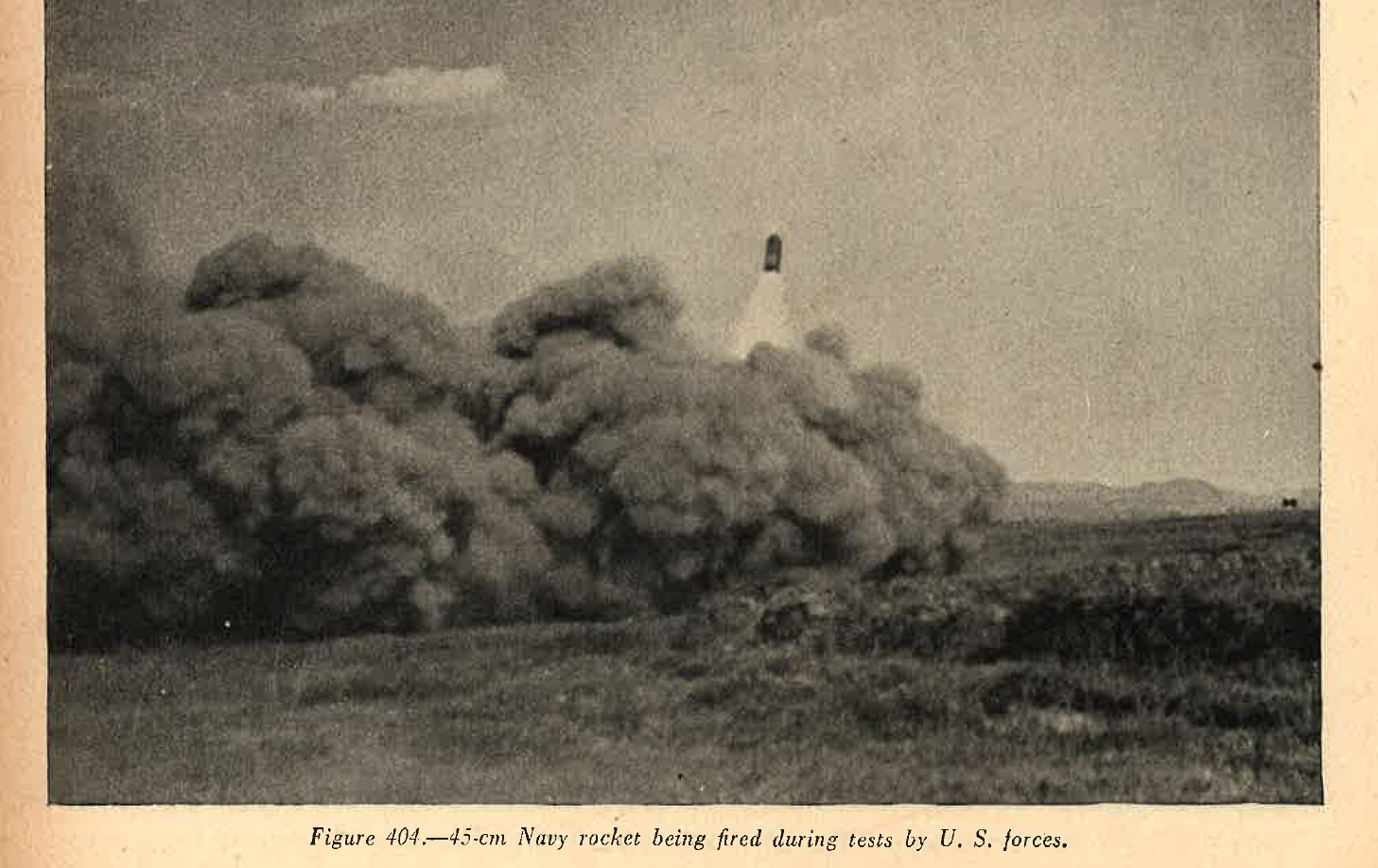
Figure 404. |
(4) Performance. A firing etst carried out recently with three of these projectiles gave a range of about 2,100 yards. Although the flights of the rockets were slightly unsteady during the descent, all three projectiles functioned well. The craters made were about 9 feet deep and 20 feet in diameter; in addition, fires were started up to a distance of 340 yards from the point of impact.
a. WWII Japanese Antiaircraft rockets
Although it has now been definately established that the Japanese are using antiaircraft rockets, the exact form which these take has not yet been determined since no speciment so far ( as of 1944) have been captured. Projectiles eiher used now or expected soon include an HE rocket, which explodes at about 8,000 feet, and possibly another projectile, of the parachute and cable type, for use st loweraltitudes as protection against low flying aircraft.
b. WWII Japanese Aircraft rockets
As it is the case with anti-aircraft rockets, it is known that experiments have been and are being carried out with air-to-air and air-to-ground rockets. Air-to-air projectiles have been used, but no details are available since no specimens have yet been recoverd (as of 1944). It is also known that the Japanese have been carrying out experiments with rocket assisted aerial bombs.
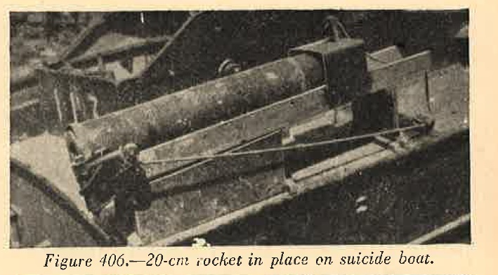
c. WWII Japanese Rocket launcher mounted on suicide motor boat.
Suicide motor boats recently captured have been found carrying two 120-mm (4.7 inch) rockets in addition to the standard 560-pound explosive charge. The rockets are mounted in the stern of the craft, one on each side of the cockpit. The rocket is of conventional spin-stabilzed design, consisting of a warhead and a rocket motor. The warhead contains a small HE charge, of about 0.75 pounds, and a number of pellets filled with a white phosphorus incendiary mixture. There is no nose fuse, but the HE charge is set off by a powder train which is ignited by the burning propellant. The rocket motor is a parallel cylinder screwed into the rear of the warhead. The rear of the motor is closed by a base plug containing six offset venturi drillings and a percussion igniter. The propellent charge consists of six sticks and an ignition charge at the forward end of the motor. When the percussion igniter is struck, the flash passes along the body to the ignition charge which in turn sets off the propellent charge.
|
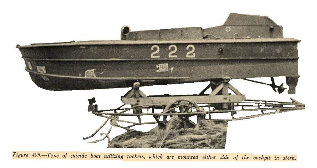 |
Two types of launchers have been recovered. On of these is a U-shaped wooden trough mounted on the gunwale and fixed for elevation and direction. A percussion hammer is pivoted at the rear of the launcher and attached to a lanyard leading to the cockpit. The projectile is retained in position on the launcher by a metal band at the rear end and a small wooden peg passing through the top of a metal cover at the forward end. The peg is removed immediately before firing.
 |
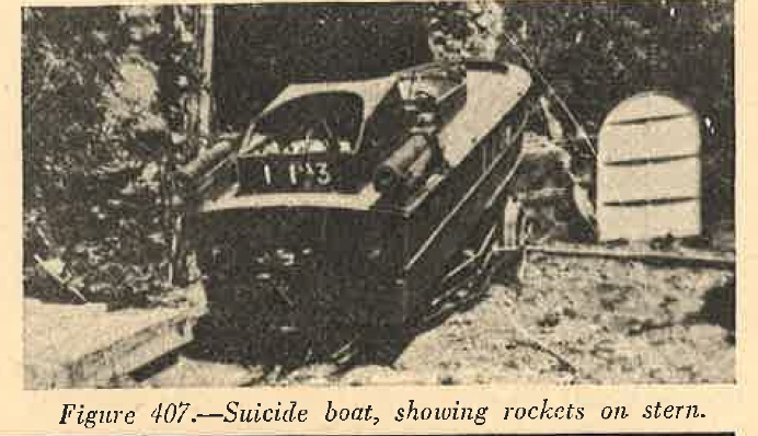 |
The other type of launcher is similar, but can be set for elevation. In this case the launcher is mounted not on the gunwale but on a vertical plate at the side of the cockpit. A clamp on the inside of this plate is used to get the launcher at the required elevation.
It is estimated from initial trials that the warhead explodes after the projectiles have traveled about 2,000 yards. The burning pellets were scattered 600 feet forward and 60 feet on each side of the point of detonation.
SECTION IX - WWII JAPANESE GUIDED MISSILES.
1. GENERAL.
a. Trends. The Japanese are begining to use rocket weapons in a large scale and have recently introduced their first guided missile. Since there are indications that further development in this class of weapon is to be expected, the following definitiona are included by way of explanation and for future guidance.
b. Guided missiles. A guided missile is one which;
(1) Like an artilery projectile, is normally designed to make a single journey to the target (although in some cases provision is made for retrieving the missile) and
(2) is guided in flight by either remote control (direct or indirect, e.g. wire or radio respectively), or an internal control, which may be either mechanical or human.
c. Rocket propulsion system. In a rocket propulsion system the oxygen required for the combustion of the propellant is carried within the propulsion unit. Units of this type can be divided into two classes - solid fuel units and liquid fuel units.
In solid fuel units, the oxygen for the combustion of the powder fuel is contained within the powder itself. This unit, when once ignited, burns to completion. Oxygen in liquid fuel units may be contained within the fuel or may be furnished by an oxidizing agent such as liquid oxygen. This type of unit employs separate tanks for the fuels which are pumped into a combustion chamber for ignition, hence combustion is under control.
d. Jet propulsion system.
In a jet-propulsion system the oxygen necessary for the combustion of the fuel is obtained from the surrounding atmosphere. Units employing this system can be divided into the following three classes:
(1) Turbo-jet propulsion units. In this unit a turbine driven compressor is used to compress air forced into the propulsion unit. This air is mixed with the fuel for combustion.
(2) Impulse or pulsating jets. These jets utilize the ram of the surrounding atmosphere to compress the air, although the intake is intermittent. Air is forced into the het system until the combustion takes place. after combustion the internal pressure is greater than the outside pressure thereby closing the air intake. When the internal pressure decreases, the air intake reopens, and the combustion takes place again. This cycle is repeated at a given rate.
(3) Ram or athodyd jets. Ram or athodyd jets utilize the continuous ram of the surrounding atmosphere to compress the air. This airis mixed with the fuel for combustion.
2. WWII JAPANESE AIRBORNE PILOTED MISSILES.
a. General
The only guided missile of this class so far recognized is Baka, in which a human suicide pilot is used for control purposes. The word Baka means fool. Evidence exists that suicide pilots will be used in other future missiles.
b. WWII Japanese Piloted rocket glide bomb, Baka.
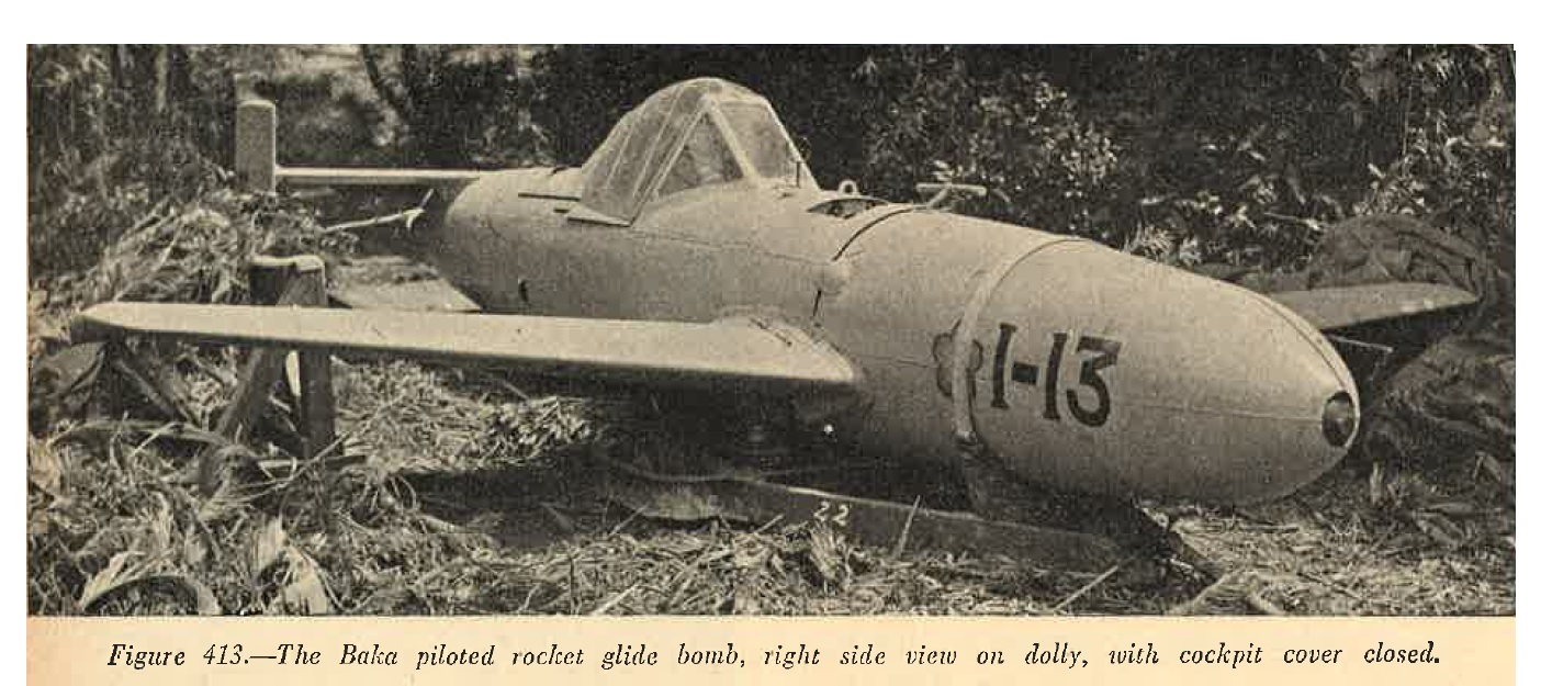
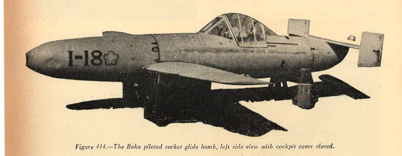
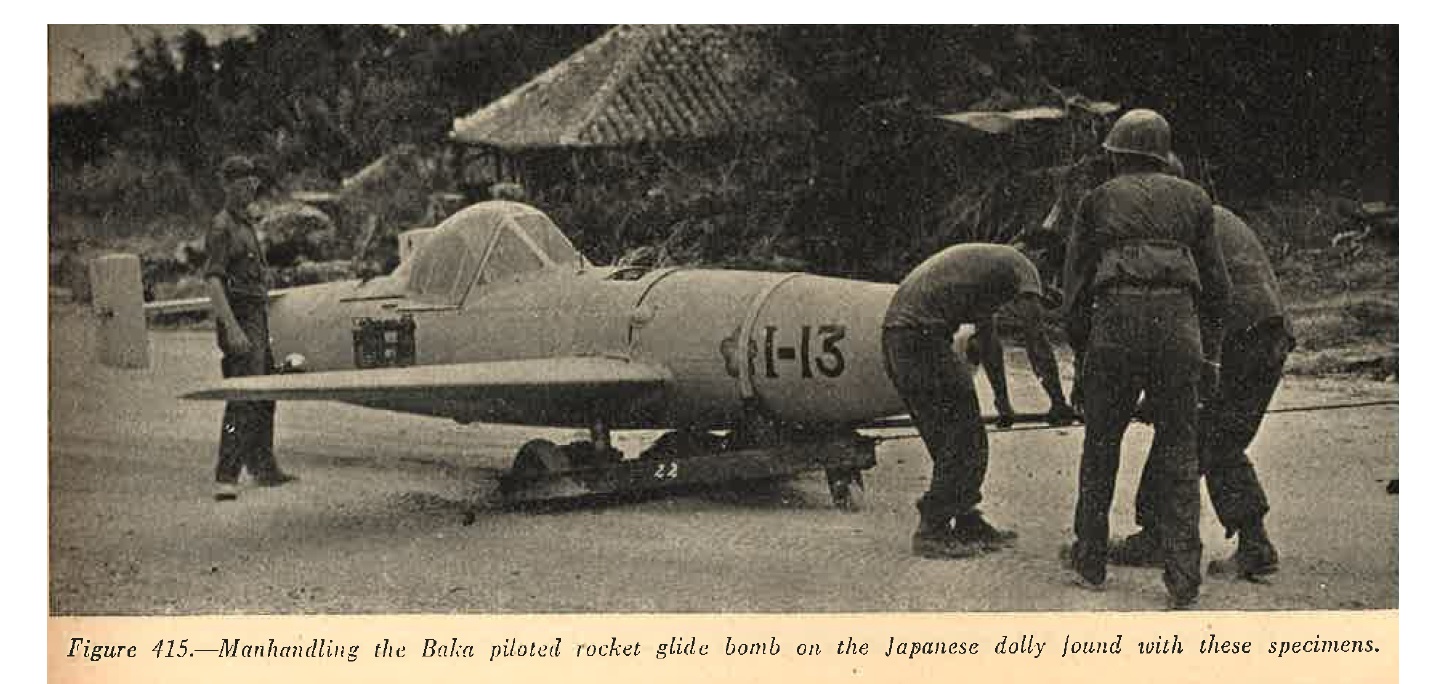
(1) General. This missile ressembles a very small airplane having a pilot's cockpit, conventional controls, and a solid fuel rocket unit. The construction characteristics are very simple and clean cut. The fuselage is made of aluminum alloy, while the wings and tail unit are made of plywood.
Baka is designed primarily for suicide attacks on shipping. This missile may also be used for ramming low-level bomber formations and also against ground targets such as depots and assembly areas.
(2) Description. The missile is a low mid-wing, monoplane type with a narrow round fuselage and a prominent nose. The wings are stubby and moderately sept back. A flat rectangular tailplane is mounted on top and to the rear of the fuselage. The missile has twin square fins with rudders. The pilot's cockpit is located behind the trailing edge of the wing.
|
 |
The three main rocket units are located in the rear section of the fuselage. Some of the Bakas have a mounting under each wing for a rocket unit. The warhead is located in the nose section.
 |
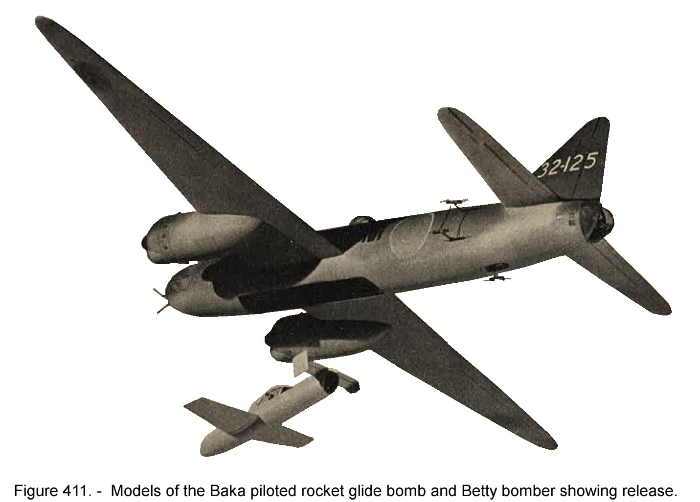 |
(3) Launching and performance. the actual operational use of this missile has been confirmed by action photographs of a Betty aircraft carrying the bomb underneath its fuselage as shown in Figure 411.
 |
 |
 |
Peggy 1, Helen 2, Sally 2, Frances 11, adn Rita 11 aircraft would also be satisfactory launchers. The maximum theoratical range of Baka when launched from 27,000 feet is calculated to be 55 miles.
SECTION X - WWII JAPANESE CHEMICAL WARFARE.
1. MARKING OF WWII JAPANESE CHEMICAL MUNITIONS
Indications are that the Japanese attention to war gases has been confined largely to the well-known types such as blister, tear, and vomiting gases. In addition, agents for the production of screening smokes are manufactured. The Japanese distinguish between screening smoke and toxic or tear clouds by referring to the latter as "special smoke". Agent containers are identified according to physiological effect of the gases by a color marking as shown below:
| NUM | TYPE OF GAS | BAND | COLOR |
| |
|||
| 1. | Choking | --------- | Blue. |
| |
|||
| 2. | Tear | --------- | Green. |
| |
|||
| 3. | Blister | --------- | Yellow. |
| |
|||
| 4. | Vomiting | --------- | Red. |
| |
|||
| 5. | Blood and nerve poisons | --------- | Brown. |
| |
|||
| 6. | Screen smokes | --------- | White. |
| |
The complete munition is referred to in the same manner, that is, a "red" shell contains vomiting gas. Chemical projectiles and most chemical aerial bombs are generally gray in color. Filled shells usually have a red band at the nose, followed by a blue band to indicate the necessity for special handling because of the chemical filling. The type of gas filling is indicated by a colored band, about twice as wide as any other color band on the shell. A narrow yellow band is believed to indicate an HE burster charge, while a narrow white band indicates that the projectile is constructed of steel.
2. WWII JAPANESE GAS BOMBS
A Type 92 (1932) 50-kilogram (110 pound) gas bomb has been encountered. This bomb contains 50.6 pounds of 50 percent mustard and 50-percent lewisite mixture. It may be recognized by the gray body and tail, a red and a blue band around the nose, two yellow bands, and one white band around the body. It is 45 inches long, 7.5 inches in diameter, and weighs 110 pounds.
3. WWII JAPANESE GAS SHELLS
a. General.
It is believed that gas munitions are provided for many types of weapons. The following shells are known to be filled with war gases (as of 1944).
b. Type 92 (1932) 75-mm vomiting gas (red) shell.
The exterior of the shell is of conventional design. However, an inner canister, containing a large bursting charge, extends the full interior length of the shell. The space between the canister and the body of the shell contains a relatively small quantity of chemical agent. This projectile may be fired from any Japanese 75-mm field guns were fitted with the suitable cartridge case. When fired from the Type 38 (1905), Type 38 (1905) improved, Type 41 (1908) cavalry, Type 41 (1908) mountain, and Type 90 (1930) field guns, the complete shell (projectile and case) is known as the Type 92 (1932) red shell. When used with the Type 94 (1934) mountain gun it is called the Type 94 (1934) red shell.
Characteristics;
|
c. Japanese Type 92 (1032) 75-mm blister gas (yellow) shell.
This projectile consists of two parts: The shell body and the burster assembly. The burster tube, containing a pressed pellet of picric acid, screws into the nose of the shell. The shell body is filled with a mixture of mustard and lewisite.
It is believed that this projectile may be fired from any Japanese 75-mm field guns when fitted with the suitable cartridge case. When fired from the: Type 38 (1905),
Type 38 (1905) improved,
Type 41 (1908) cavalry
Type 41 (1908) mountain
Type 90 (1930)
field guns, the complete shell (projectile and case) is known as the Type 92 (1932) yellow shell. When used with the Type 94 (1934) mountain gun it is called the Type 94 (1934) yellow shell.
Characteristics;
|
d. Japanese Type 92 (1932) 75-mm choking gas and smoke (blue-white) shell.
The body of this projectile is identical with that of Type 92 (1932) blister gas shell. The filling consists of a mixture of phosgene and a smoke agent. Similar to the Type 92 (1932) blister and Type 92 (1932) vomiting gas shells, it may be fired from any of the Japanese 75-mm field guns and follows the same system of type designation.
Characteristics;
|
 |
e. Japanese Type 95 (1935) 90-mm vomiting (red) mortar shell.
It is believed that this shell closely ressembles the standard Type 94 (1934) 90-mm HE shell in external appearance, except for color markings. This shell may be fired from both the Type 94 (1934) and Type 97 (1937) 90-mm mortars.
Characteristics;
|
f. Type 95 (1935) 90-mm blister gas (yellow) mortar shell.
This sell closely ressembles the Type 95 (1935) 90-mm vomiting gas shell in general appearance. The color markings, however, are different. The Type 95 (1935) bliter gas shell may be fired from both the Type 94 (1934) and Type 97 (1937) 90-mm mortars.
Characteristics;
|
g. Japanese Type 90 blood-nerve poison (Brown) mortar shell.
Although little is known about this unrecovered shell, it is reported to contain hydrocyanic acid and has a total weight of 14.4 pounds. It is fired from both Type 94 (1934) and Tyope 97 (1937) 90-mm mortar.
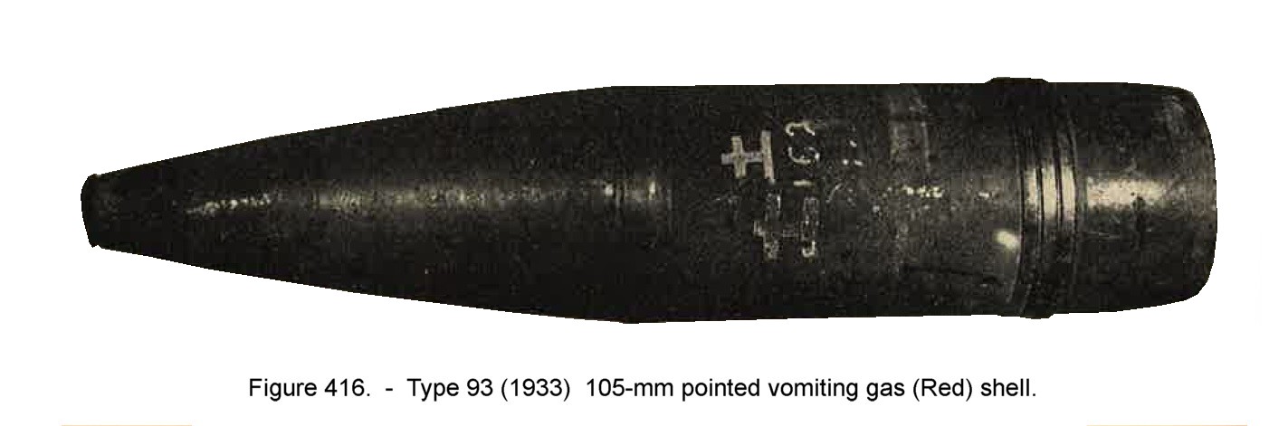
h. Japanese Type 9h (1933) 105-mm pointed vomiting-gas (red) shell.
This hsell is characterized by a single, copper rotating band, a copper bourrelet, and a long, pointed ogive. In general appearance, with exception of teh color markings, it closely resembles the pointed HE shell. The Type 93 (1933) 105-mm pointed vomitting gas shell can be fired from both the Japanese 105-mm guns and howitzers when fitted with the suitable cartridge case.
Characteristics;
|
i. Japanese Type 92 (1932) 105-mm blister-gas (yellow) shell.
Little information is available concerning this unrecovered projectile. It is believed to have a total weight of 34.8 pounds and a chemical filling of 4.9 pounds. It is assumed that it is fitted with the Type 88 (1928) instantaneous fuze, and may be fired from both Japanese 105-mm guns and howitzers.
j. Japanese 105-mm choking-gas and smoke (blue-white) shell.
All that is known of this projectile is that it contains 4.3 punds of 90 % phosgene and 10 % smoke agent.
k. Japanese Type 93 (1933) 150-mm pointed vomiting-gas (red) shell shell.
This projectile is characterized by a single, copper rotating band, a copper bourrelet, and a long, pointed ogive. The body is made in two sections. The forward section, which contains the bursting charge, is threaded to the rear section well forward of the bourrelet. The chemical filling is contained in the rear section. The Type 93 (1933) 150-mm pointed vomiting gas shell is known only to be fired from the Type 4 (1915) 150-mm howitzer. It is possible, however, that it also may be fired from the Type 38 (1905) howitzer and, perhaps, guns of this caliber as well, when the shell is fitted with the suitable cartridge case.
Characteristics;
|
l. Japanese Type 92 (1932) 150-mm pointed blister gas (yellow) shell.
This projectiles has a one piece steel body; characterized by a single, copper rotatig band, a copper bourrelet, and a long, pointed ogive. The bursting charge is in the form of a long booster consisting of three pellets of TNT. The Type 92 (1932) 150-mm pointed blister gas shell is known to be fired from the Japanese Type 4 (1915) 150-mm howitzer. It is possible that when fitted with the suitable cartridge case it may be fired also from the other 150-mm howitzers and guns.
Characteristics;
|
m. Japanese Type 92 (1932) 150-mm pointed choking gas and smoke (blue-white) shell.
It is believed that this shell uses the same body as the Type 92 (1932) pointed blister-gas shell and can be fired from the same weapons.
Characteristics;
|
n. Japanese 150-mm blood-nerve poison (brown) shell.
Unlike the other 150-mm chemical projectiles, this is not a pointed shell but has a short, rounded ogive. In addition, it has a flat base and lacks the copper bourrelet. It is probably fired from the same weapons as the other Japanese 150-mm chemical shells.
Characteristics;
|
o. Japanese 150-mm gas mortar shells. No details are known of gas-filled mortar shells of this caliber. However, it is believed that shells exist filled with vomiting, blister, and blood-nerve poisons.
4. WWII JAPANESE GAS GRANADES
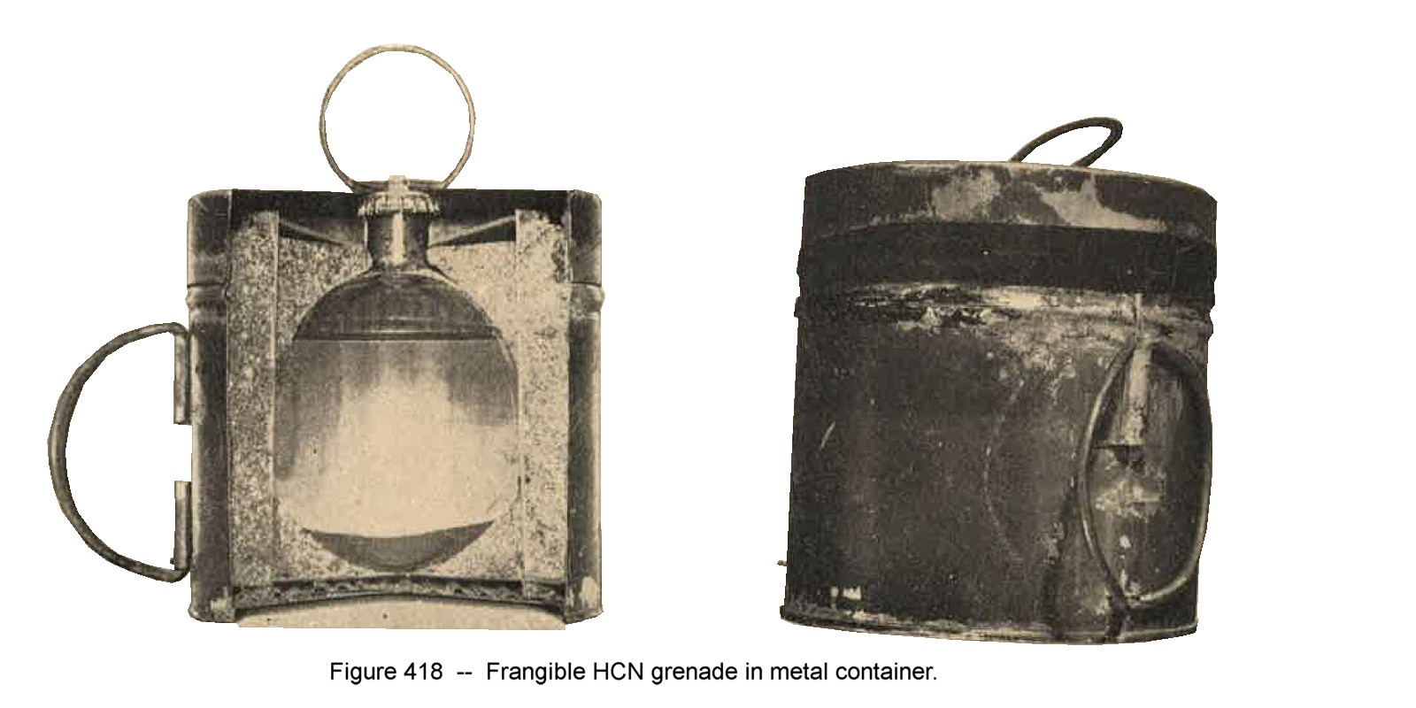
a. Frangile Hydrocyanic acid HCN grenades.
(1) General. Two types of this grenade have been recovered (as of 1944). Both grenades consist of a spherical glass flask, with a short neck sealed with a rubber or cork stopper and crown cap, and filled with hydrocyanic acid plus a stabilizing agent.
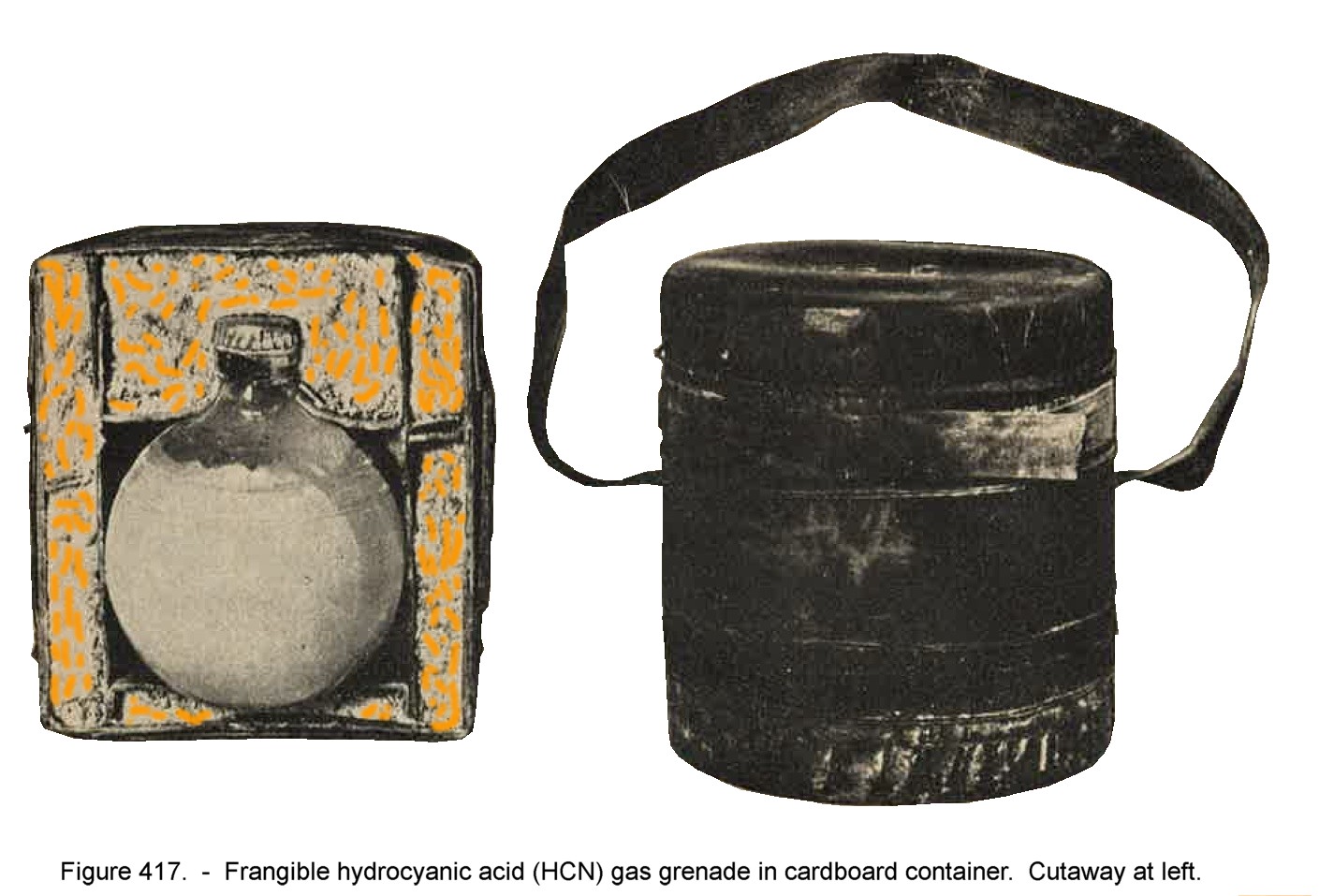
One of these grenades is packed in a cylindrical metal container, fitted with a wire handle on top and two wire handles on the side. The other grenade is packed in a cylindrical cardboard container, fitted with a web carrying strap. Both types of containers are painted olive-drab and have a cylindrical inner pocket which holds the grenade, around which is packed sawdust and a neutralizing agent of soda ash.
(2) Frangile HCN grenade (in metal container) The hydrocyanic-acid filling of this grenade contains a stabilizing agent of copper powder.
Characteristics;
|
(3) Frangile HCN grenade (in cardboard container) The hydrocyanic acid filling of this grenade contains a stabilizing agent of arsenic trioxide.
Characteristics:
|
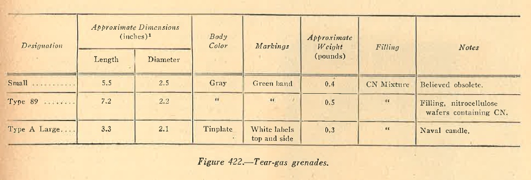
b. Type 92 (1932) tear-gas (Green) grenade.
To date (1944), no speciment of this grenade has been recovered. Indications are that by addition of a propellent container similar to that used with the Type 91 (1931) HE grenade it may be fired from both the Type 10 (1921) and Type 89 (1929) grenade dischargers. In addition it may be thrown by hand.
Characteristics:
| 1. | Weight of chemical filling | --------- | 1.3 ounces. |
| 2. | Nature of bursting charge | --------- | TNT. |
| 3. | Weight of bursting charge | --------- | 1.06 ounces. |
| 4. | Type of fuze | --------- | Type 10 (1921) |
c. Type 92 (1932) vomiting-gas grenade.
No speciment of this grenade has been recovered to date. Indications are that it may be thrown by hane or, by addition of propellent container, fired from the Type 10 (1921) and Type 89 (1929) grenade dischargers.
Characteristics:
| 1. | Nature of chemical filling | --------- | Diphenylcyanarsine ("Red Mark I"). |
| 2. | Weight of chemical filling | --------- | 1,4 ounces. |
| 3. | Nature of bursting charge | --------- | TNT |
| 4. | Weight of bursting charge | --------- | 1.06 ounces. |
| 5. | Type of fuze | --------- | Type 10 (1921). |
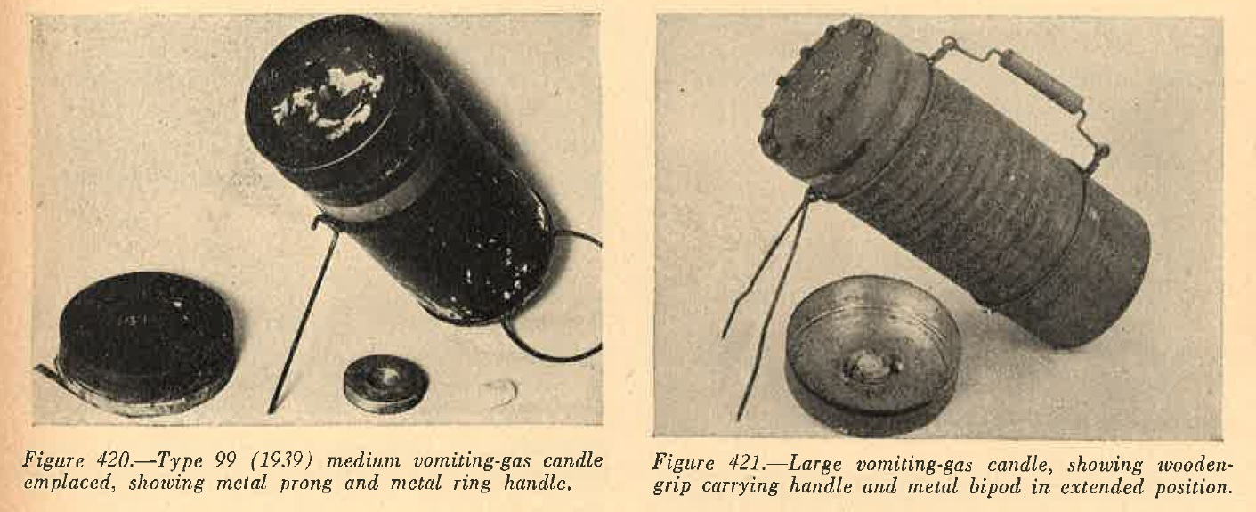
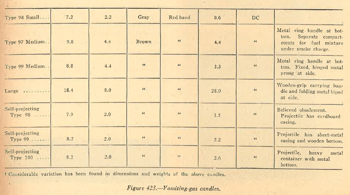
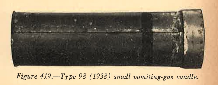
5. WWII JAPANESE GAS CANDLES
Most Japanese gas and smoke candles of the stationary and hand-thrown type are fired by matchhead fuze and scratcher block. All Japanese self projecting gas and smoke candles are provided with an outer container equipped with a sliding metal spike. Before firing the candle, this spike is driven into the ground to maintain the candle at the desired angle.
A matchhead at the lower end of the candle is then ignited with a scratcher block and sets off the propellent charge, which expels the inner container (projectile) carrying the main charge. The main charge is then set off by a delay fuze ignited by the flash of the propellent charge. Japanese self-projecting smoke candles can also be fired from specially designed multi-barrel launchers. The candles are set off wither manually by using a scratcher block, or electrically by means of a small heating coil fitted over teh matchhead.
6. WWII JAPANESE SMOKE BOMBS
a. One kilogram (2.2 pound) smole-antipersonnel bomb.
This bomb is used as a marker in conjunction with demolition bombs. On explosion, antipersonnel effect is achieved by fragmentation of the cast iron body.
Characteristics.
| 1. | Overall length | --------- | 10.5 inches. |
| 2. | Body diameter | --------- | 3 inches. |
| 3. | Filling | --------- | Picric acid burster and red phosphorus smoke charge. |
| 4. | Markings | --------- | White rubber nose, black body, white tail cone and fins. |
b. 50-kilogram (110 pound) smoke bomb.
Characteristics.
| 1. | Overall length | --------- | 40 inches. |
| 2. | Body diameter | --------- | 7 inches. |
| 3. | Filling | --------- | 50.6 pounds of sulfur trioxide chlorsulfonic acid (FS smoke) |
| 4. | Color and markings | --------- | Gray body and tail; red band around nose. Smoke symbol "KE". |
7. WWII JAPANESE SMOKE SHELLS
a. Type 95 (1935) 50-mm smoke shell.
This shell is fitted with a copper rotating band and, except for a time fuze, closely resembles the Type 89 (1929) HE shell in external appearance. The Type 95 (1935) smoke shell can be fired from the Type 89 (1929) 50-mm grenade discharger only.
Characteristics:
| 1. | Weight, fuzed | --------- | Approximately 2.4 pounds. |
| 2. | Length fuzed | --------- | Approximately 5.7 inches. |
| 3. | Length, withuot fuze | --------- | Approximately 4.3 inches. |
| 4. | Maximum diameter | --------- | 1.97 inches. |
| 5. | Body material | --------- | Steel. |
| 6. | Nature of smoke filling | --------- |
Hexachlorethane : 45 % Zinc: 17% Zinc oxide: 35.5% Zinc chloride 3.6 % |
| 7. | Weight of smoke filling | --------- | 3.53.ounces. |
| 8. | Type of fuze | --------- | Type 89 (1929) small, time. |
| 9. | Duration | --------- | 1 minute. |
| 10. | Screening effect | --------- | Five rounds cover a front of 55 yards. |
| 11. | Minimum range | --------- | 110 yards. |
| 12. | Maximum range | --------- | 436 uyards. |
| 13. | Color markings | --------- |
Black body; Red band below fuze; White band around body above rotating band; White band below bourrelet |
b. Type 11 (1922) 70-mm smoke shell.
This projectile is fired from the Type 11 (1922) 70-mm mortar, and although no specimen has been recovered, it is assumed that the body length of the projectile (unfuzed) would approximate that of the HE shell (7.1 inches). In addition, it is probable that the body would be painted black with a red band immediately below teh fuze and two white bands around the body.
Characteristics:
| 1. | Weight, fuzed | --------- | 6.1 pounds. |
| 2. | Nature of smoke filling | --------- | White phosphorus. |
| 3. | Weight of smoke filling | --------- | 15.2 ounces. |
| 4. | Type of fuze | --------- | Type 88 (1928) small instantaneous. |
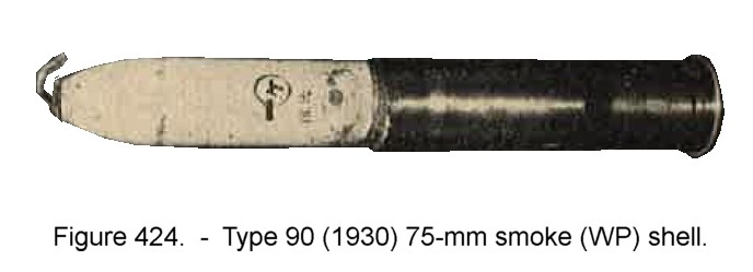
c. Type 90 (1930) 75-mm smoke shell.
This projectiile has a steel body and, when fitted to teh suitable carriage case, may be fired from any of the Japanese 75-mm field guns.
Characteristics:
|  |
d. 90-mm smoke shells.
Two models, the Type 97 (1937) and Type 94 (1934) experimental model, have been identified. Available evidence indicates that they are similar, and it is assumed that the Type 97 (1937) is the production designation of the experimental Type 94 (1934) sheel. Both shells are fitted with the Type 5 (1916) combination (time and impact) fuze, and contain six canisters of smoke composition, which in the case of the Type 94 shell have a total weight of 2.64 pounds. It would appear that the object of the time fuze is to secure an air burst, thus scattering the canisters over a wide area. Both shells may be fired from the Type 94 (1934) and Type 97 (1937) 90-mm mortars.
e. Type 14 (1925) 105-mm smoke shell.
This shell has not been recovered (as of 1944), but it is thought to be fired from the Type 14 (1925) and Type 38 (1905) field guns. The projectile, fitted with Type 5 (1916) combination (time and impact) fuze, weighs 35.6 pounds, and contains 5.7 pounds of White Phosphorus.
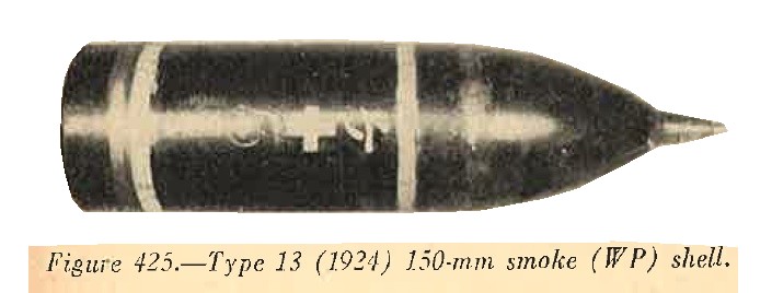
f. Type 13 (1924) 150-mm smoke shell.
This projectile may be fired from the Type 38 (1905) and the Type 4 (1915) 150-mm howitzers.
Characteristics:
|
 |
8. WWII JAPANESE SMOKE GRENADES
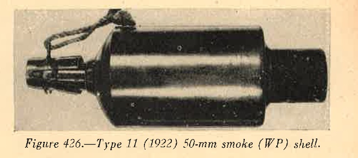
a. Type 11 (1922) 50-mm smoke grenade.
This is a hand grenade which, by the addition of a propellent container screwed to the base, may be fired from both the Type 10 (1921) and Type 89 (1929) 50-mm grenade dischargers. The fuze, propellent container, and methods of firing are similar to Type 10 (1921) HE grenades. No data are available concerning the screening effect of this grenade, but it is assumed that it would have approximately the same range as Type 91 (1931) HE grenade.
Characteristics:
|
 |
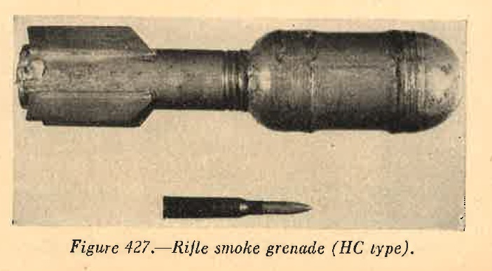
b. Rifle smoke grenade (HC type).
This fuzeless rifle grenade consists of a light, metal body containing a smoke mixture, a finned tail piece, and a removable rounded nose cap. The grenade is fired from the same spigot launcher as the Type 91 (1931) HE grenade, and uses the same type of blank cartridge with wooden bullet. On firing, the flash of the propellent initiates an igniter pellet in the base of the grenade body, which in turn ignites the smoke mixture.
The heat generated opens four ports in the base of the grenade body, through which the smoke escapes. The blank cartridge is normally contained in the tailpiece which is sealed by adhesive tape and paraffin. A length of cord is attached to the blank cartridge for ease of removal.
Characteristics:
|
 |
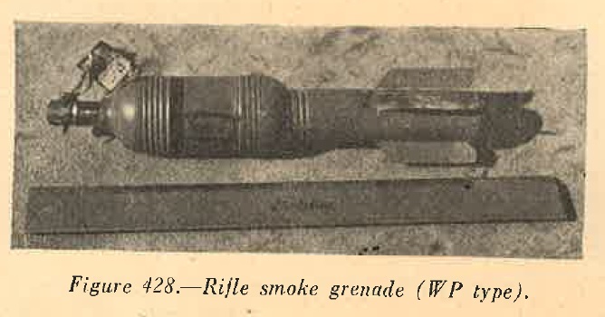
c. Rifle smoke grenade (WP).
This grenade consists of a White Phosphorus filled steel body and a finned tailpiece. The addition of a nose fuze and a 0.5 inch purple band around the body distinguishes it from the HE type rifle grenade. The delay nose fuze is initiated by setback. The grenade uses the same spigot launcher as the Type 3 (1943) HE grenade and is fired by means of a similar blank cartridge from both the 6.5-mm and 7.7-mm rifles.
Characteristics:
|
 |
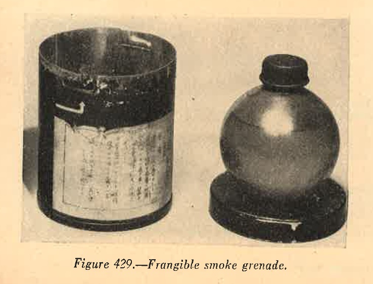
d. Frangible smoke grenade.
This grenade cosists of a spherical glass flask with a flat bottom and short neck. The flask is sealed with a rubber stopper retained by a double crown cap. The smoke filling is a yellowish liquid, varying from 100 percent titanium tetrachloride to a mixture of approximately 60 percent titanium tetrachloride and 40 percent silicon tetrachloride. Prior to use, the grenade is cushioned in sawdust and packed in cylindrical sheet metal container. The glass flask is broken on impact, causing the smoke reaction.
Characteristics:
|
 |
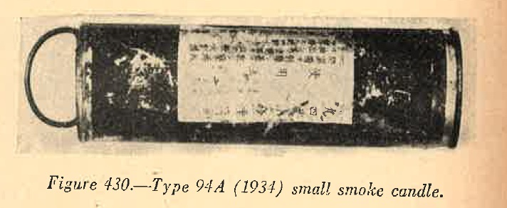
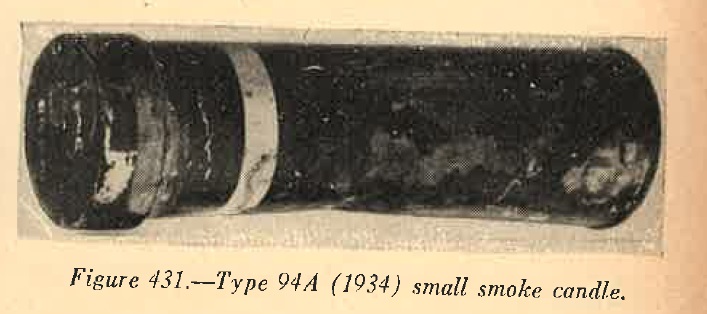
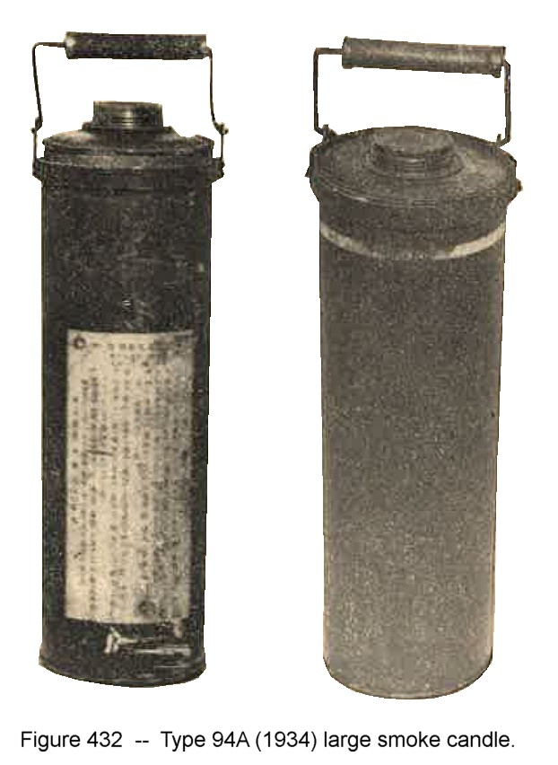
9. WWII JAPANESE SMOKE CANDLES
 |
 |
 |
 |
 |
 |
 |
 |
 |
 |
10. WWII JAPANESE 40-KILOGRAM (88 POUND) SMOKE GENERATOR, FLOATING
This is a gray welded, steel cylinder, 14 inches high abd 12 inches in diameter, with spray nozzle and ignition system on top. An inflated rubber float can be attached to lugs welded to the casing. The smoke charge consists of 60 pounds of sulfur trioxide chlorosulfonic acid (FS smoke).
11. WWII JAPANESE INCENDIARY BOMBS
a. General.
Army type incendiary bombs are painted gray, while the HE bombs are Black. Navy type bombs, both HE and incendiary, are painted gray. Red and Silver tail struts usually designate an incendiary filling.
b. 32-Kilogram (70.5 pound) incendiary bomb.
|
 |
c. Type 97 (1937) 50-kilogram (110 pound) incendiary bomb.
|
d. Type 100 (1940) 50-kilogram incendiary bomb.
|
e. 60-kilogram solid oil bomb, Navy type.
|
f. Type 97 (1937) 60-kilogram (132 pound) incendiary thermite bomb, Navy type.
|
g. 250-kilogram (551-pound) HE incendiary bomb.
|
12. WWII JAPANESE INCENDIARY SHELLS
a. General.
The following shells, which have a chemical filling of White Phosphorus alone, are listed in this section for reference. They are probably used primarily for their screening effect, and specifications will be found under "Smoke shells", Paragraph 14 of this section.
The following shells are believed to be used primarily for their incendiary effect. b. Type 90 (1930) 75-MM incendiary shell. This shell has never been recovered (as of 1944), but iut is believed that it could be fired from any of the Japanese 75-mm field guns, when fitted to the correct cartridge case. After a pre-set time, or on impact, the combination fuze fires an expelling charge, the incendiary element being forced out through the base of the projectile.
|