CHAPTER - 9 JAPANESE WWII ROCKETS

SECTION VIII - WWII JAPANESE ROCKETS.
1. GENERAL.
Japanese rocket weapons, although only comparatively recently introduced, are progressing rapidly, and production models are already begining to appear. This progress is being made under the influence of German rocket design and with the assistance of German experiments with rocket weapons. It is this assistance which is enabling the Japanese to bypass some of the stages between initial experiments and the appearance of production models.
The initial rocket weapons recovered were very crudely designed and consisted mainly of improvisations. Typical of such crudity of design are the Type 10 and Type 3 rocket motors, which are used to push a 60-kilogram (132 pound) bomb off a launchign ramp and so give it the initial impulse necessary to continue its flight. A furthwe development of this weapon, and representative of improvisation stage, is the 30-cm rocket, which consists of a 250-kilogram bomb with tha tail assembly replaced by a fin-established rocket motor.
The early types of launchers were eqyually as crude as their projectiles. Those used with the first rocket motors were metal or wooden trough-shaped ramps supported at the forward end by some simple form of bipod.
The first evidence of influence of German rocket design was the appearance of the 20-cm Navy spin-stabilized projectile. Althought this rocket was an improvisation, consisting of a cut down naval shell with a rocket motor attached to the tail, it showed that the Japanese were beginning to conisider the use of spin-stabilization. Further evidence of German influence is shown by the replacement of the original trough-shaped launcher by one of the tube type, the first of its kind to be used by the Japanese.
It is now believed that both this projectile and its launcher were experiments in the development of the 20-cm Army spin-stabilized rockets and the type 4 launcher. This rocket, and even more certainly the launcher, since it is the first launcher to which a type number has been given, appear to be production models and represent the present stage of development of ground rocket weapons.
| It may be expected, therefore, that the Japanese will continue with experiments and production of spin-stabilized rockets, and that projectiles analogous to if not actually identical with those developed by the Germans will appear in the near future. However, development in other classes of rocket weapons, such as antiaircraft and aircraft projectiles, remain in the primitive stages. During the past few months, many reports have been received of air-to-air, air-to-ground, and ground-to-air missiles, a number of which appear to have been rocket assisted. Also, documentary evidence shows Japanese interest in the development of rocket assisted aerial bombs and points to the production of at least one missile of this type. It would seem reasonable, therefore, to expect that in this field, also new types of rocket projectiles will shortly appear. Initial experiments indicate that aircraft projectiles probably prove to be of the conventional, fin-stabilized type launched from under the wings of fighter aircraft. |
Figure 383. WWII Japanese Rocket launcher emplacement on Iwo Jima. |
If German influence prevails, antiaircraft rockets may appear as "parachute and cable" projectiles. Among oher developments which can be expected is an antitank rocket weapon similar to the American bazooka. A recent Japanese radi broadcast stated that projectiles of this type are being produced at a rate of one million per month. Undoubtedly this is a great exaggeration, but it is fairly certain that a weapon of this class is under production. This may prove to be an adaptation of either the German Raketenpanzerbuchse 43 or the American bazooka.
Finally the stage of development may be summed up by the statement that Japanese rocket weapons are only on the brink of large scale development and production, and the future can be expected to show great progress in this field of armament.
2. GROUND-TO-GROUND ROCKETS.
a. General. The following types of ground-to-ground rocket projectiles have been identified; Type 10 19-cm rocket motor;
Type 3 19-cm rocket motor;
20-cm Navy rocket;
20-cm Army rocket;
30-cm special Mark I roclet motor;
45-cm naval rocket;
b. Type 10 19-cm rocket motor.
(1) General.
This weapon used for launching Type 97 60-kilogram land bomb, differs from the conventional type of rocket projectile in that the rocket motor does not form an integral part of the projectile. The motor is separate and serves merely to propel the bomb out of an inclined trough-shaped launcher. It is one of the earlier Japanese rocket weapons and may be considered obsolescent if not obsolete. Although the original bomb with which this rocket motor was used is the Type 97 60-kilogram (132 pound) land bomb, a later version of this motor, the Type 3 is used with both this bomb and the 63-kilogram (138.6 pound) ordinary bomb. It would appear reasonable ro assume, therefore, that any conviniently sized bomb weighing about 60 kilograms could be used.
Figure 391. Single and triple wooden trough launcher for baval 20-cm rocket.
(2) Construction.
The rocket motor is of simple construction and consists of a propellant chamber, a closing plate, and a tail assembly incorporating a single venturi tube. The propellant chamber is filled with three sticks of propellant and is closed at the forward end by a nose cap. The nose cap is drilled centrally to take an electrical igniter which bears against an ignition charge at the forward end of the propellant. A conical wooden spacing block fits over the igniter; four grooves in this block engage the tail fins of the bomb and form the connection between it and teh rocket motor.
Characteristics:
|
(3) Launching. The rocket and bomb are launched from a trough-shaped launcher. The rocket is placed in the launcher, and the leads from the electrical igniter in the nose are connected to a small exploder in the firing position. The bomb is then placed in the launcher and slid to the rear so that the fins engage with the wooden spacer on the nose of the rocket motor. The metal cover of the launcher is then closed, and teh projectile is ready to fire. The elevation of the launcher is controlled by a cable passing from the base plate round the lower ends of the two bipod legs and back to the base plate. A number of eyes on each side section of the cable enables the launcher to be set at different elevations by linking the eyes to hooks on the bipod legs.
(4) Performance According to a Japanese range table this projectile may be fired up to 1,200 meters (1,311.6 yards).
c. Type 3 19-cm (7.41 inch) rocket motor.
(1) General.
This rocket is a lengthened version of the Type 10 19-cm rocket motor and, like the Type 10, it does not form an integral part of the complete projectile, but serves merely to propel the bomb out of a trough-shaped launcher. This motor is used both with the Type 97 60-kilogram land bomb and with the 63-kilogram ordinary bomb.
(2) Construction.
The motor is constructed in the same way as the Type 10 rocket motor and consists basically of the propellant chamber, the closing plate, and a tail assembly which incorporates a single venturi tube. Like the Type 10 rocket motoe. This has an electrical igniter at the nose end and an ignition charge at the forward end of the propellent chamber. The same or a similar wooden spacing block is used to connect the rocket motor to the bomb.
|
Figure 384. Type 10 19-cm rocket motor, with the Type 97 60 Kilogram bomb and launcher. |
(3) Launching.
This rocket motor is launched in the same way as the Type 10 (Figure 384). The rocket motor is placed in the launcher, and the leads from the electrical igniter are connected to the exploder. The bomb is then placed in the launcher and connected to the rocket motor by the wooden spacing block. Like the Type 10, this tocket motor is fired from a concealed position to the flank of the launcher.
Figure 386. View of a Type 3 (1943) 19-cm rocket motor. |

Figure 387. A Type 3 (1943) 19-cm rocket motor after discharge. Showing the motor imbeded in an airstrip. |
(3) Performance.
No details of the performance of this projectile are available. Since the rocket motor is the same as the Type 10 with the exception of the increased length of the propellent chamber, it is probablr that the maximum range is somewhat in excess of that of the Type 10, probably about 1,900 yards.
Figure 385. Type 3 (1943) 19-cm rocket motor in position on a launcher, ready to propel a 63 kilogram bomb.
d. Japanese 20-cm (7.8 Inch) Navy rocket.
(1) General.
This rocket was the first spin-stabilized projectile to be recovered and consists of what appears to be a cut-down 3 inch naval shell to the base of which a rocket motor has been attached. Although and improvisation, this projectile reflects the design of certain German rockets, having the HE filling forward and a propellent compartment to the rear. The thin wall of the warhead and teh scale on the launcher indicate that this projectile has been designed as a short-range weapon (about 2,000 yards), relying for effect upon blast rather than upon fragmentation.
|
(2) Construction. he warhead of the rocket is of normal design and is fitted with a point detonating nose fuze. The rear end of the warhead is closed by a plate threaded externally to fit into the forward end of the rocket motor. The rocket motor is a plain cylinder of the same diameter as the warhead, and threaded intermally at the rear to take a motor base plate has six offset verturi drillings and a central hole to take a percussion igniter. The propellent consists of seven sticks, six of which are located around an identical severnth stick. The sticks make a reasonably tight fit inside the propellent chamber and are held in place by two grids, one at each end of the chamber. The forward grid contains an ignition charge. When the percussion igniter is struck, teh flash passes along the central stick of propellent and initiates the ignition charge, which in turn sets off the propellent charge. |
|
Figure 393. Tube-type 20-cm Navy rocket launcher. |
Figure 392. Tube-type 20-cm Navy rocket launcher. |
| | |
Figure 390. 20-cm Navy rocket, wooden trough launcher. |
Figure 389. 20-cm Navy rocket and trough launcher. |
e. Japanese 20-cm Army rocket.
(1) General. Two types of 20-cm spin stabilized projectiles have been recovered; since the correct individual nomenclatures are not yet known, they have provisionally been designtaed the "older type" and the "newer type", the distinction lying in the shape of the rocket motor. In the case of the "older type", the sides of the rocket motor are straight, while in the "newer type" the wall of the rocket motor is machined down in the center to give a bourrelet effect at the ends. The latter for this reason is often referred to as the "bourrelet type". Apart from this difference in the external appearance of the rocket motor, the two projectiles are basically the same and the following description applies equally to both types.
Figure 395. Packaging of the 20-cm Army rocket; the newer type motor is shown at left rear, the older type at right front; the projectile is seenat left front.
(2) Construction. The projectile is of conventional spin-stabilized design and consists basically of an explosive head and a propellent compartment. It apparently has been developed from the Navy spin-stabilized projectile of the same caliber. However, the size of the rocket motor in the Army projectile has been increased to give the projectile greater range.
The warhead is a thin-walled cylinder with an ogival shaped nose. The rear end is closed by a plate which forms the junction with the rocket motor. The rocket motor is a cylinder threaded internbally at each end. The forward end screws on to the plat ein the base of the warhead, and the rear end is closed by a base plate with 6 offset venturi tubes. A hole in the center of the base plate takes a pull igniter.
The propellent consists of seven sticks, six of which are arranged around the central stick; The latter is in two parts, and either half or all of this stick is sometimes removed. The sticks are held in position by two grids, one at each end of the propellent chamber. The ignition charge in this rocket is located at the rear end of the propellent compartment, just forward of the pull igniter in the base plate.
Characteristics;
|
Figure 394. New type 20-cm Army rocket, showing machined-down walls if the rocket motor. See also Figure 395. |
(3) Launching. This projectile is launched from the Type 4 (1944) launcher (figure 396). This launcher is of particular interest since it is the first one to which a type number has been given and therefore represents the first regular production model.
Figure 396. Type 4 (1944) 20-cm rocket launcher. |
The launcher is similar in appearance to a standard mortar and consists basically of a tube, base plate and bipod. The lower half
of the tube is split so that a portion can be raised for loading the projectile. When the projectile has been loaded, this
portion is lowered and secured in position by four quick-release catches, two on each side of the tube.
The bipod is of usual mortar bipod design, incorporating the normal elevating and traversing gears and a cross leveling gear attached to the right leg. A collimator sight, the same as that used with the 81-mm and 90-mm mortars, is mounted on the left of the traversing gear. |
The base plate is a ehavy rectangular plate supporting a cup in which rests a spherical projection on the base of the tube. In Figure 396 the base plate is reversed. The stakes should be forward as in Figure 397.
Figure 397. Type 4 (1944) 20-cm Army rocket launcher, breech open. The base plate is shown correctly emplaced.
Since the projectile is fired by means of a lanyard attached to the pull igniter in the base plug, the launcher has no firing mechanism.
(4) Performance. Tests carried out recently show that this weapon is surprisingly accurate. In one test, six rounds, fired at a range of 3,000 yards, landed within an area 100 yards long by 90 yards wide.
f. Japanese 30-cm special Mark I rocket motor.
(1) General. This is a fin-stabilized motor of simple design used for launching either of two types of 250-kilogram (551-pound) bombs. The rocket motor is in many respects a scaled up version of Type 10 and 3, being fin stabilized and having an electrical firing mechanism at the forward end, but in this case the rocket motor is directly attached to and not just resting behind the bomb.
The only specimen of this projectile recovered (as of 1944) was composed of the rocket motor and the Navy Type 98 250-kilogram land bomb. According to a Japanese manual, the rocket motor used in conjunction with this bomb is known as Type 21, and when used with the Type 99 250-kilogram ordinary bomb, it is designated Type 22. Since the actual rocket motor appears to be the same in each case, this difference in nomenclature can be accounted for only by the slight difference in the two types of adapters used to connect the rocket motor to the bombs.
Figure 399. The 30-cm Special Mark I rocket with bomb attached, in position on trough-shaped metal ramp. |
(2) Construction. The warhead is formed by the case of the 250 kilogram bomb with the tail unit removed. An adapter sleeve fits into the tail of the warhead and the forward end of the rocket motor. The rocket motor is of simple construction and consists of the body, a base cap, and a fin assembly incorporating a single venturi tube. The forward end is closed by a nose cap which fits into the adapter sleeve. A central drilling in this nose cap takes an electrical igniter which connects with an ignition charge inside the propellent chamber. Two electrical leads from the igniter pass through drilling in the adapter sleeve and are connected to a small exploder. A grid at the rear end, and probably another at the forward end, support the propellent charge. No details about the propellent are available since it had been removed from the single speciment recovered. |
The base cap is conical in shape and screws into the rear of the body. The tail assembly, which comprises a single venturi tube to which are welded four stabilizing fins, is screwed into the rear of the base cap.
Characteristics;
|
Figure 389. Views of the 30-cm Special Mark I rocket motor, with bomb shown in the lower photograph. |
(3) Launching. The launcher for this projectile is a crude, trough shaped, metal ramp similar to those used for the 19-cm rocket motors. In this case, however, the sides of the launcher are stepped outwards. Like other launchers of this type, this one is supported at the
The projectiile is carried in two parts: the rocket motor and the warhead. The motor and warhead are assembled for launching, and the leads from the electrical igniter are passed through the drilling in the adapter sleeve. The whole projectile is loaded into the launcher, and the leads are connected to the exploder which is in the firing position at oneflank. The projectile is now ready for firing.
(4) Performance. Although the Japanese manual credits this projectile with a maximum range of 10,000 meters (10,900 yards), the maximum recorded range is only 7,500 yards, at which accuracy was very poor. The flight of the rocket is erratic, being greatly affected by wind currents. The rocket can be recognized easily by a distinctive "bubble whistle" sound in flight.
g. Japanese 45-cm (17.55 Inch) Navy rocket.
(1) General. This is the second of two types of Navy rocket projectiles to be recovered, the first being the 20-cm Navy rocket. The 45-cm projectile is basically a scaled-up version of the 20-cm rocket and has the same internal layout (HE filling forward and propellant to the rear) and a percussion igniter in the center of the base plug. Like the 20-cm rocket, this projectile is nose fuzed.
(2) Construction. The warhead is a cylindrical tube with a conical nosepiece welded to the forward ends. Both the body and the nosepiece are of sheet steel, rolled and welded. The junction between the warhead and the rocket motor is formed by a sleeve coupling fitted into the body of the warhead and secured by internal and external welds. The nose fuze is either the standard Type 100 mortar fuze or the naval point-detonating fuze used with the 20-cm rocket.
The body of the rocket motor is a steel cylinder, threaded internally at the forward end to screw onto the sleeve coupling. The rear end of the motor body is closed by a base plug containing six offset venturi tubes. A central drilling in the base plug takes a percussion igniter. Two grids, one forward and one aft, locate and support the propelling charge which consists of either 39 or 40 sticks, each with a drilling along the center. An ignition charge is tied to the forward grid. When the percussion igniter in the base plug is struck, a flash passes along the perforation in the central stick and initiates the ignition charge, which in turn sets off the propellent charge.
Characteristics;
|
Figure 400. 45-cm Navy rocket positioned for firing on a metal launcher constructed for tests by U.S. forces. |
(3) Launching. Only one type of launcher has been recovered for this projectile. This is a heavy wooden ramp, mounted on wooden wheels and provided with a firing hammer at the rear. The launcher is very crudely constructed and can only be used once, as the blast from the tail of the projectile completely burns it at one firing. as with other types of rocket launchers, a lanyard is attached to the firing hammer, and the projectile is fired from a remote firing position to the flank of the launcher.
Figure 401. 45-cm Navy rockets. |
Figure 402. 45-cm Navy rocket base plate. |
| | |
Figure 403. |
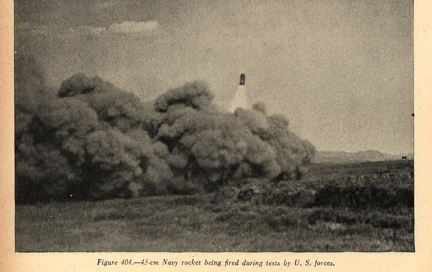
Figure 404. |
(4) Performance. A firing etst carried out recently with three of these projectiles gave a range of about 2,100 yards. Although the flights of the rockets were slightly unsteady during the descent, all three projectiles functioned well. The craters made were about 9 feet deep and 20 feet in diameter; in addition, fires were started up to a distance of 340 yards from the point of impact.
a. WWII Japanese Antiaircraft rockets
Although it has now been definately established that the Japanese are using antiaircraft rockets, the exact form which these take has not yet been determined since no speciment so far ( as of 1944) have been captured. Projectiles eiher used now or expected soon include an HE rocket, which explodes at about 8,000 feet, and possibly another projectile, of the parachute and cable type, for use st loweraltitudes as protection against low flying aircraft.
b. WWII Japanese Aircraft rockets
As it is the case with anti-aircraft rockets, it is known that experiments have been and are being carried out with air-to-air and air-to-ground rockets. Air-to-air projectiles have been used, but no details are available since no specimens have yet been recoverd (as of 1944). It is also known that the Japanese have been carrying out experiments with rocket assisted aerial bombs.
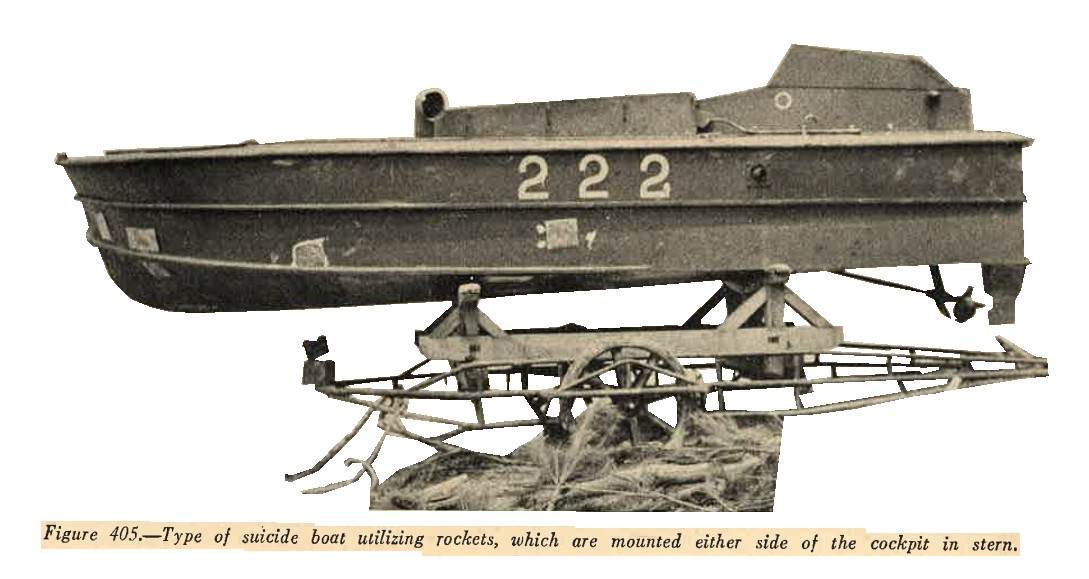
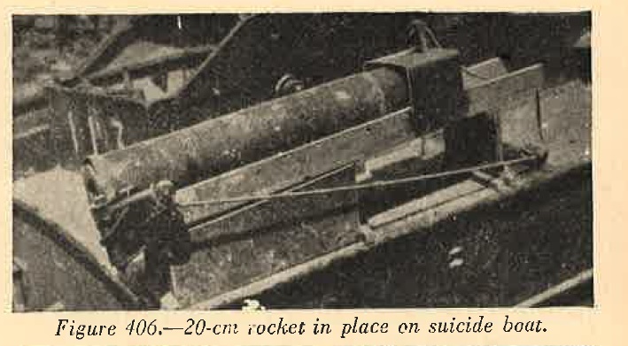
c. WWII Japanese Rocket launcher mounted on suicide motor boat.
Suicide motor boats recently captured have been found carrying two 120-mm (4.7 inch) rockets in addition to the standard 560-pound explosive charge. The rockets are mounted in the stern of the craft, one on each side of the cockpit. The rocket is of conventional spin-stabilzed design, consisting of a warhead and a rocket motor. The warhead contains a small HE charge, of about 0.75 pounds, and a number of pellets filled with a white phosphorus incendiary mixture. There is no nose fuse, but the HE charge is set off by a powder train which is ignited by the burning propellant. The rocket motor is a parallel cylinder screwed into the rear of the warhead. The rear of the motor is closed by a base plug containing six offset venturi drillings and a percussion igniter. The propellent charge consists of six sticks and an ignition charge at the forward end of the motor. When the percussion igniter is struck, the flash passes along the body to the ignition charge which in turn sets off the propellent charge.
|
 |
Two types of launchers have been recovered. On of these is a U-shaped wooden trough mounted on the gunwale and fixed for elevation and direction. A percussion hammer is pivoted at the rear of the launcher and attached to a lanyard leading to the cockpit. The projectile is retained in position on the launcher by a metal band at the rear end and a small wooden peg passing through the top of a metal cover at the forward end. The peg is removed immediately before firing.
 |
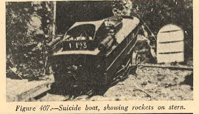 |
The other type of launcher is similar, but can be set for elevation. In this case the launcher is mounted not on the gunwale but on a vertical plate at the side of the cockpit. A clamp on the inside of this plate is used to get the launcher at the required elevation.
It is estimated from initial trials that the warhead explodes after the projectiles have traveled about 2,000 yards. The burning pellets were scattered 600 feet forward and 60 feet on each side of the point of detonation.