CHAPTER 9 - WWII JAPANESE COMMUNICATIONS EQUIPMENT

SECTION IV - WWII JAPANESE SIGNAL EQUIPMENT.
1. GENERAL.
The following data have been derived from the examination of Japanese signal equipment.
2. WWII JAPANESE RADIO EQUIPMENT.
a. WWII Japanese Ground radio.
(1) The Japanese place most emphasis on wire communication. However, radio is used initially where communications must be established rapidly or wher other means are not practicable. After wire communications have been established, radio assumes a secondary role as a stand-by communication link except where other means cannot be employed.
(2) Apparatus, to date, is of obsolescent design. Circuits and components are comparable with those used by the Allied Nations between 1935 and 1937. Transmitters and receivers almost invariably have wide frequency ranges and use plug in coils to cover the various bands. In regiments or smaller units, transmitters generally vary from approximately 1 to 50 watts. High powered sets (500 watts and above) are used primarily for Army administration traffic and air/ground liaison. Simple Hartley oscillator circuits, connected directly to the antenna, are used. The smaller receivers employ regenerative directors without radio frequency amplification. While such arrangements are simple to service and maintain, the frequency stability suffers greatly. It therefore would be difficult to "net" these ardio sets and keep them on frequency.
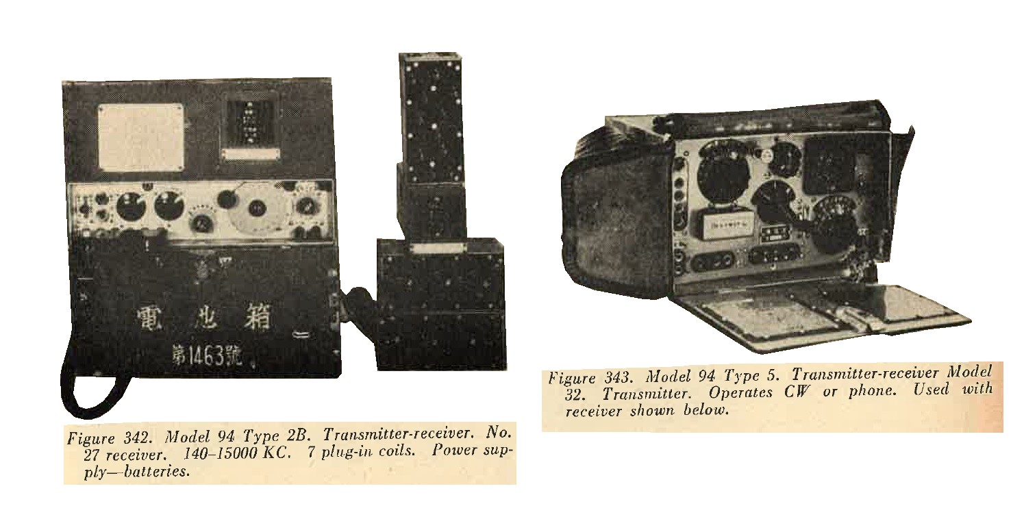
(3) A great variety of small transceivers and transmitter-receiver combinations of 1 to 2 watts power are in operation. Such sets are usually manpack. The transceivers are contained in one case which is carried on the chest; the batteries are carried in anoher case on the back. In the small transmitter-receiver models, the transmitter, receiver, batteries, and the hand generator for transmitter power, are all carried om separate cases, making it necessary for two to three men to pack and operate a set.
Sets of from 10 to 50 watts power are usually of the portable type, and are carried in 4 or 5 separate cases. Power connections are made by means of plugs and cables. The sets, in general, have a complexity of control which does not permit ease of operation. The many controls of the Direction Finder and Intercept Receiver, Model 94 (1934), Type 1, indicate that a comparatively long time is necessary to obtain an accurate "fix" on a transmitter. It must be borne in mind, however, that Japanese operators are well trained and capable of making good use of their equipment.
(4) Most of the transmitters have provision for crystal operation, and although few crystals have been found, it is reasonable to assume that crystal operation is used extensively. All crystal operated Army ground sets also can be employed as master oscillators.
(5) Since many ammeters, both for antenna and power, are supplied with separate shunts, the same meter movement can be used for many different sets.
(6) Examination of equipment shows that there is little indication of moisture or fungus proofing.
(7) All phone transmitters are amplitude modulated, and there is no evidence of frequency modulation.
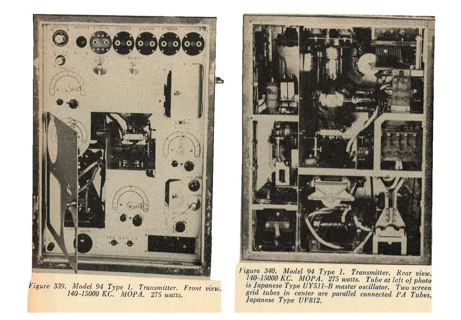
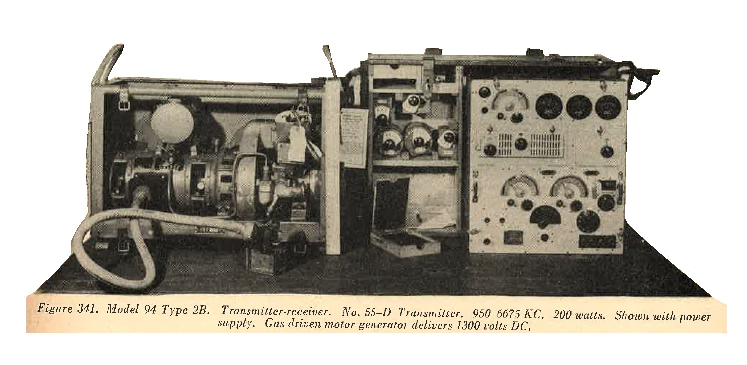
(8) Technical characteristics and photographs of sets used by Japanese ground forces are illustrated in figures 337 to 354.
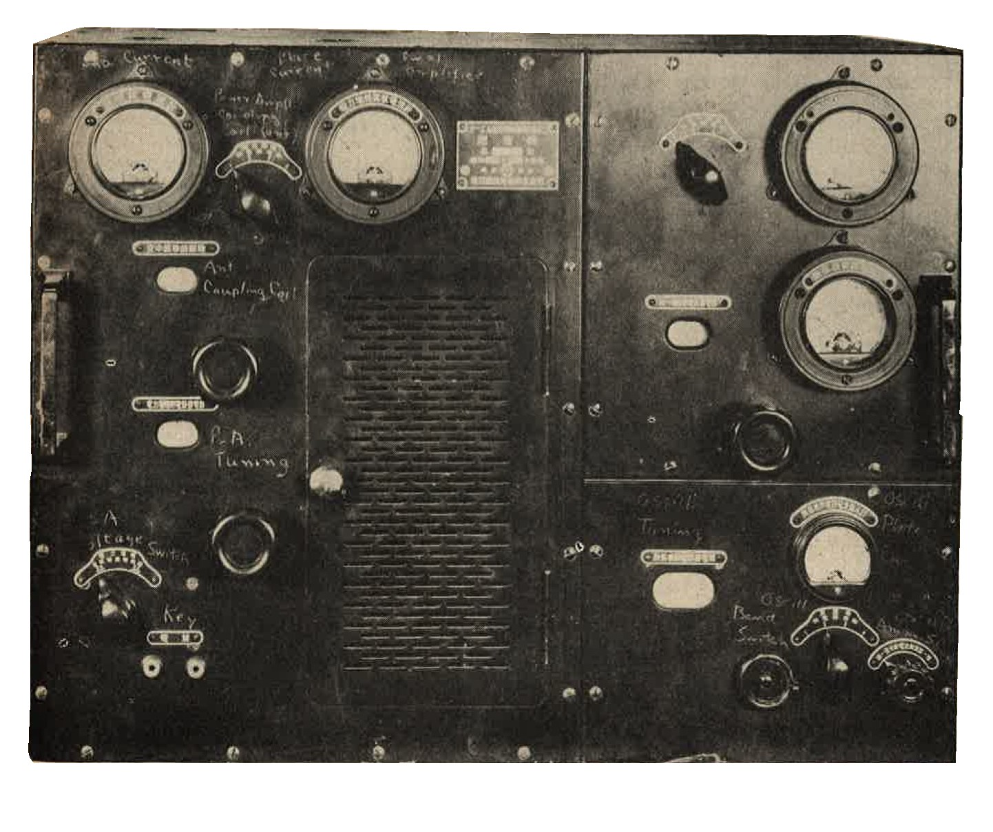
Figure 337. Model TE-MU Type 2. Transmitter. Front view. |
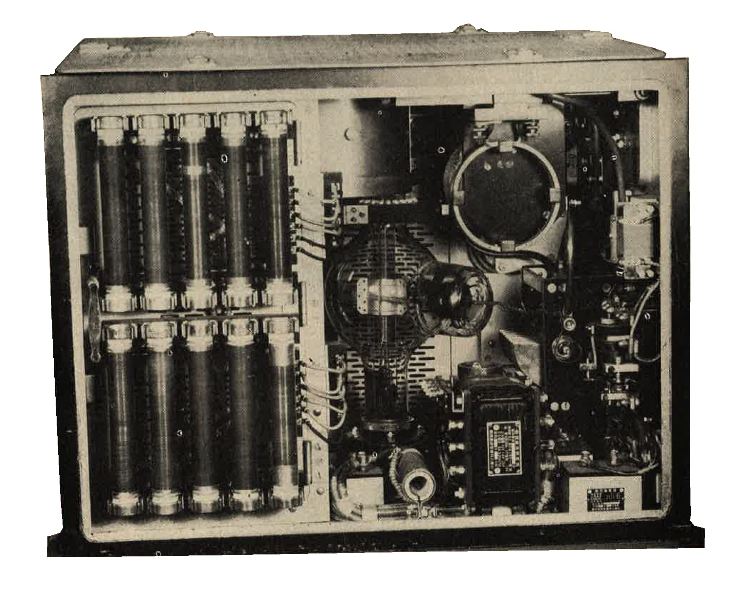
Figure 338. Model TE-MU Type 2. Transmitter. Rear view. Tube shown is Japanese Type UV812. Manufactured by Tokyo electric company. |
|
|
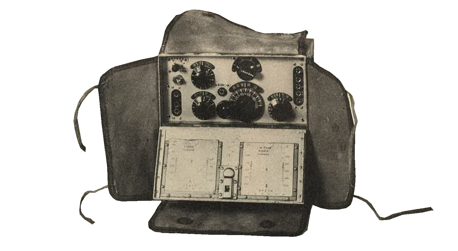
Figure 344. Model 94 Type 5. Transmitter-receiver Model 32. Receiver. |
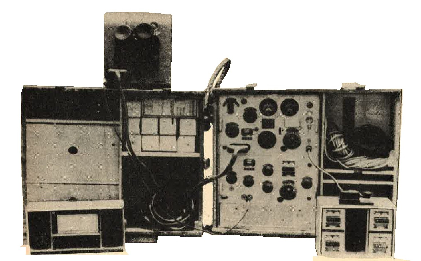
Figure 345. Model 94 3A No 36. Transmitter-receiver. Transmitter, 400-5700 KC. 15 watts. CW only. Power supply - hand generator. Receiver 350-600 KC. Power supply - batteries. |
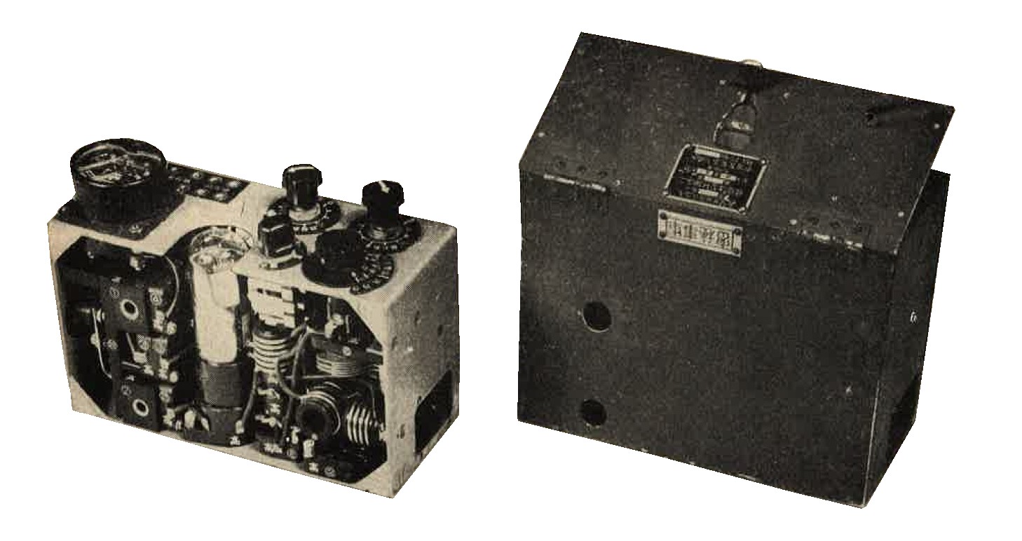
Figure 346. Model 94 Type 6. Transceiver. No 23 Model H. Date: April 1940. |
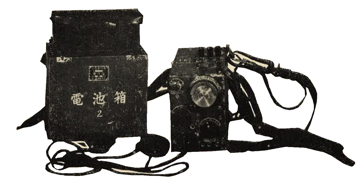
Figure 347. "Walkie Talkie" Type 66. Transceiver. Model A. 2500-4500 KC. Power supply - batteries. |
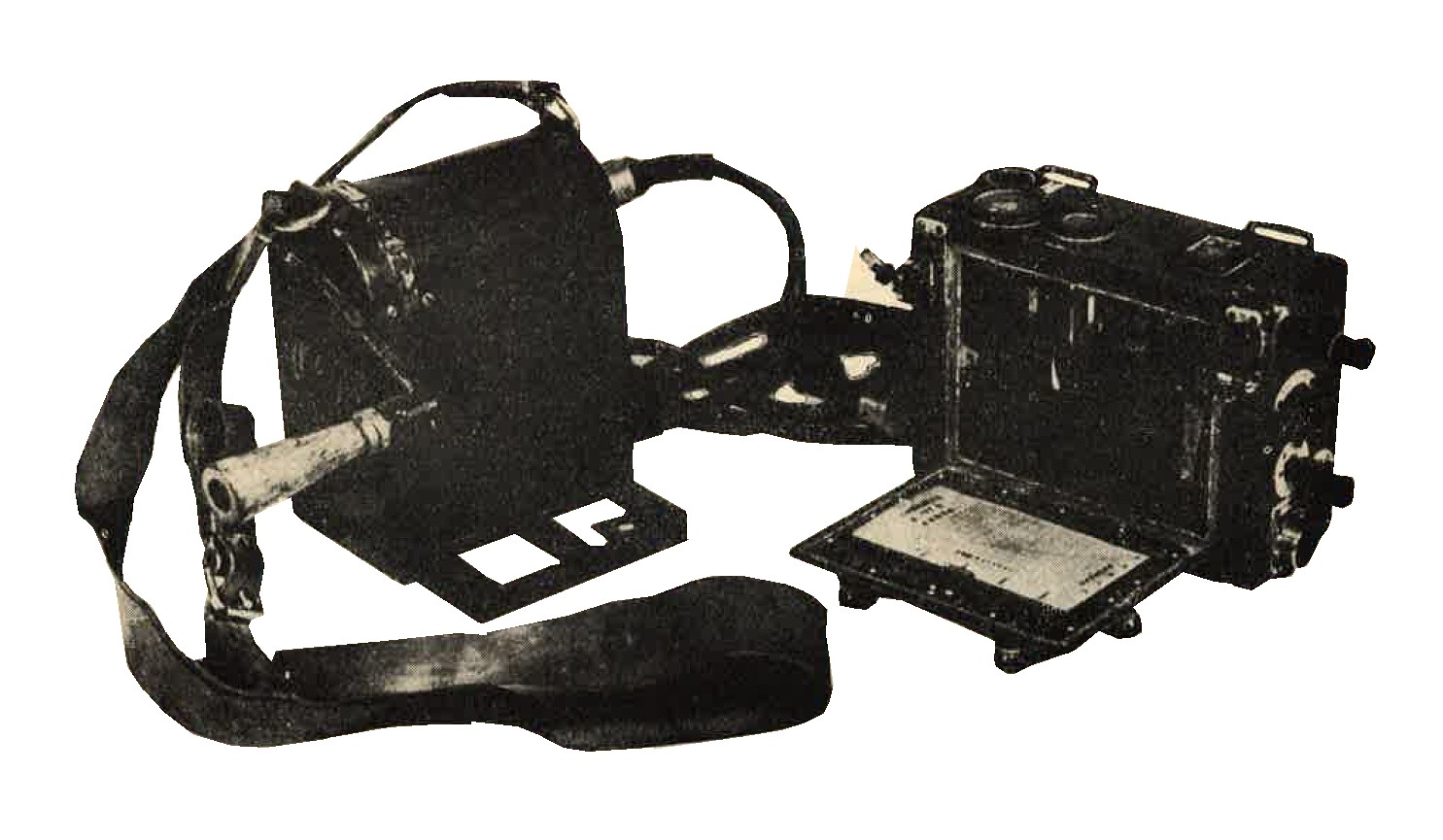
Figure 348. Model 97 Type 3. Transceiver with hand generator. Pack type. Dipole elements of antenna fasten to wing nuts at ends of case. |
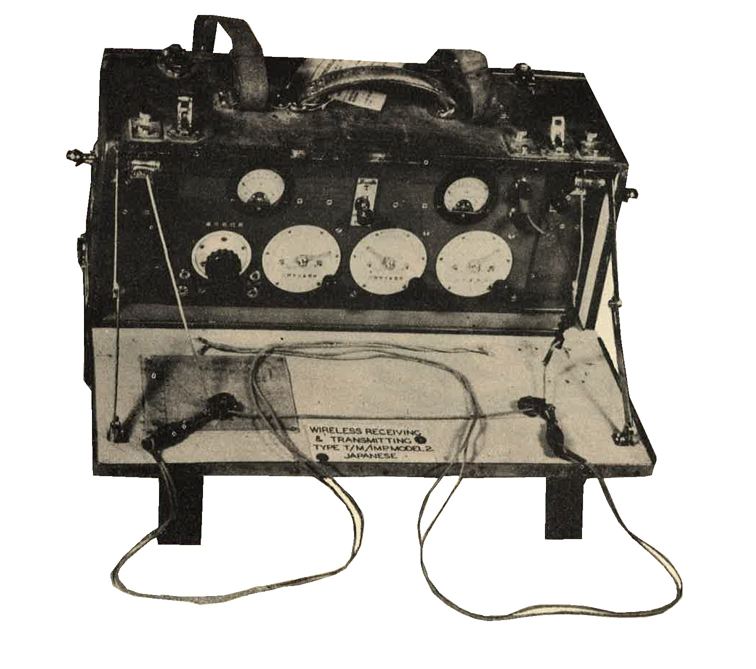
Figure 349. Model TM Type 2. Transceiver 4000-12000 KC. CW only. Power output about 1 watt. (also reported as 2.5 watts). |
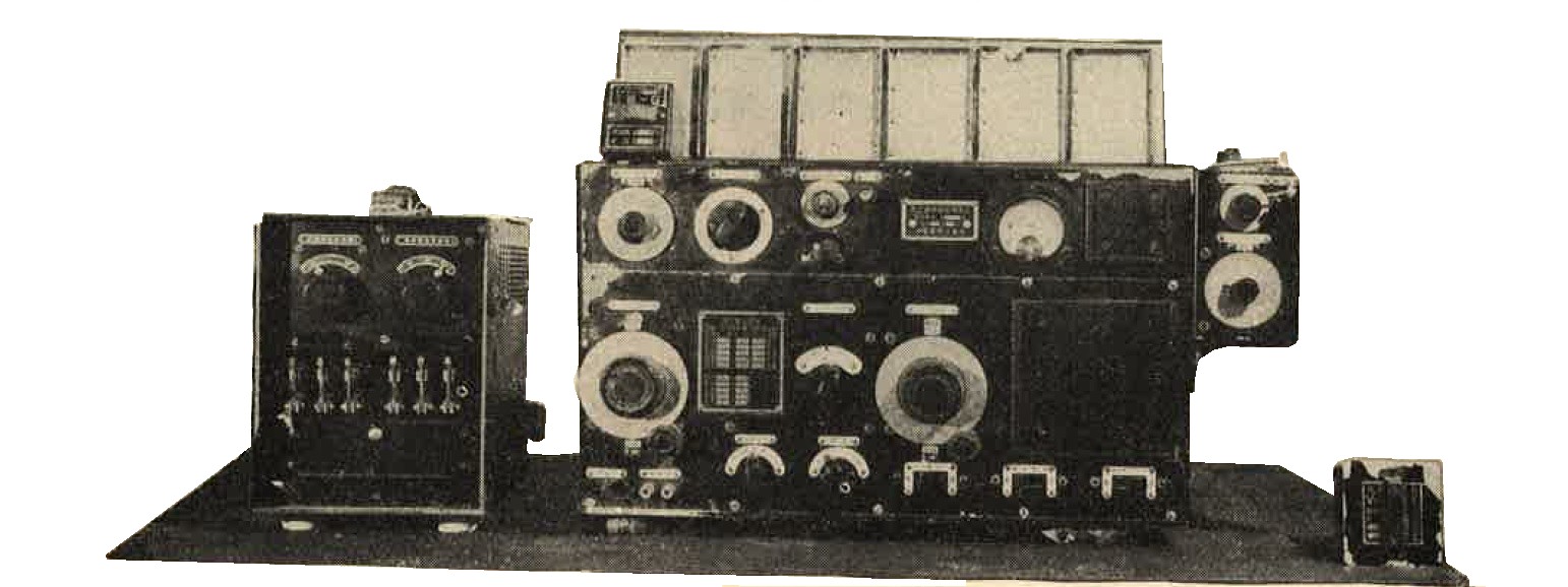
Figure 350.
Model 92 Revision 3. Tube combination TRF and superheterodyne, all-wave receiver. 200-2000 KC.
Shown with AC power supply. Delivers 75 and 200 volts DC.
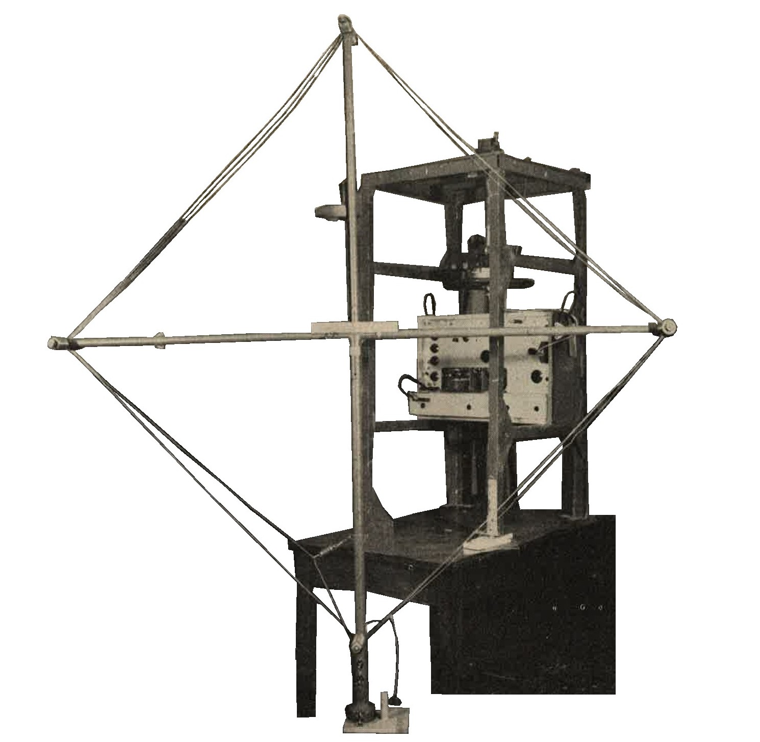
Figure 351. Model 94 Type 1. Direction finding and intercept receiver. 100-2000 KC, Loop shown dismounted from frame. |
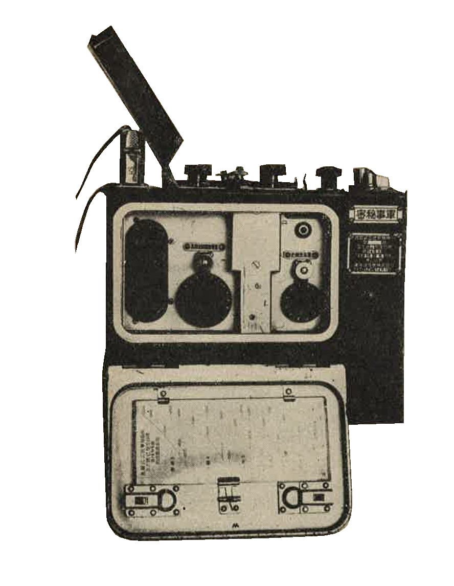
Figure 352. Model 94 Type 3-A. Receiver only. Pack type. |
b. WWII Japanese Airborne radio.
(1) Japanese airborne transmitters and receivers, sturdily and compactly constructed, are of excellent workmanship and material. More attention appears to have been given to compactness of design than to ease of maintenance. In many instances, the equipment is so constructed that it is difficult, or even impossible, to service. To some extent, sets are designed to fit a particular type of aircraft, rather than standardized for general use. It has been noted that some tubes (valves) are equipped with leather handles to facilitate removal.
Japanese equipment uses a large amount of aluminum, so that even bulky pieces are unusually light in weight. Although no precautions have been taken gainst corrosion and fungus control, reports indicate that equipment later than 1940 is far superior to that of earlier design. Electrically and mechanically, new radio equipment appears to approach Allied standards.
(2) It has been noted that not all Japanese planes have radio equipment. While radio direction finders are standard equipment on medium and heavy bombers, here have been no reports indicating that they are normally fitted to fighters.
(3) Radio equipment that was made in America, either in whole or in part, has been found on several Japanese (0) Zero fighters (Zekes). Most parts are of Japanese manufacture, but components of German and English manufacture have been noted. Exact imitations of American and German design also have been reported. there si no evidence of quantity production; indeed, all equipment noted is hand-made and of good construction. Good quality crystals are used in he majority of radios to control the frequencies of transmitters and receivers.
(4) Technical characteristics and photographs of airborne equipment are shown in Figures 355 to 363.
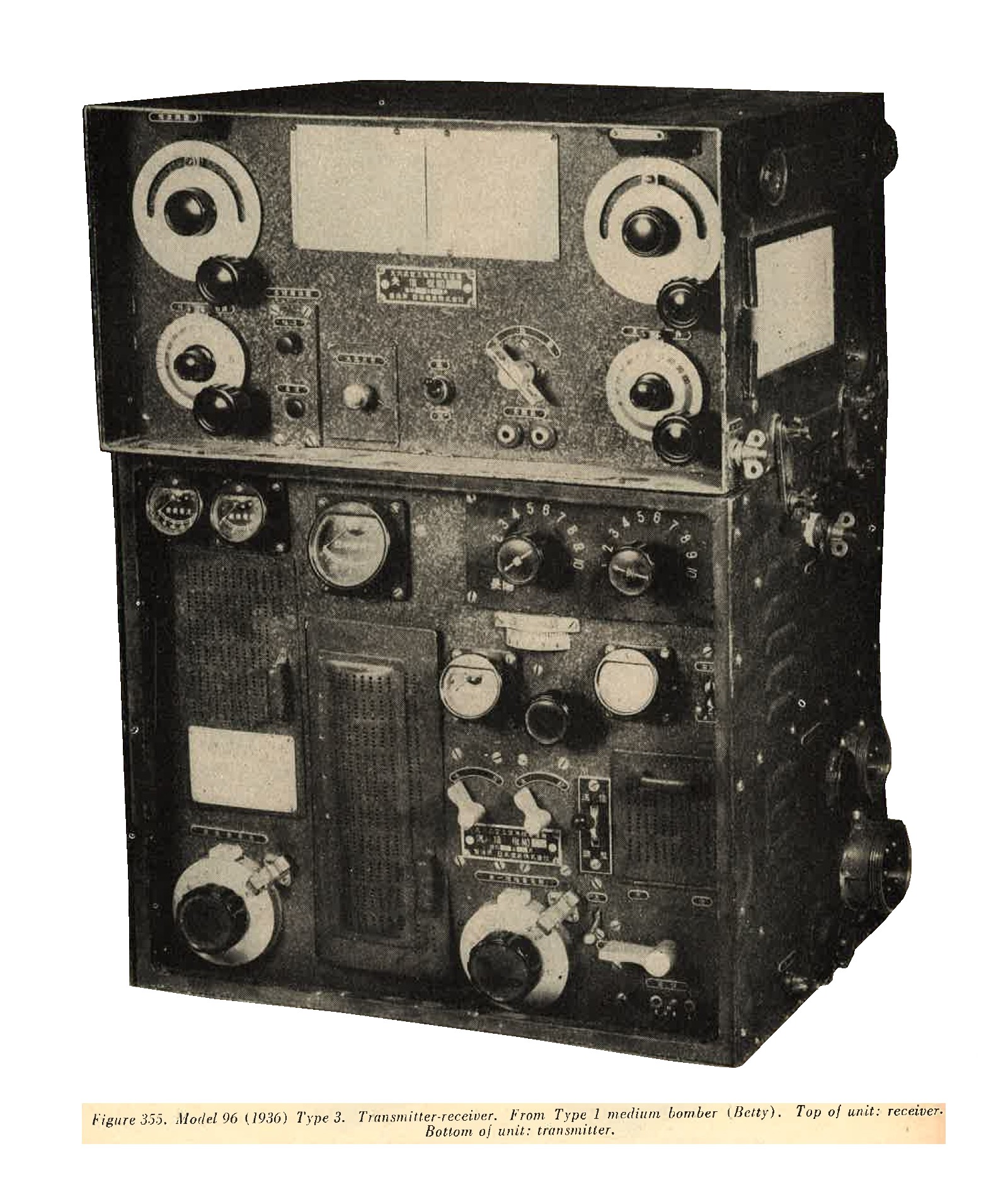
Figure 355. Model 96 (1936) Type 3. Transmiter - receiver. From Tyoe 1 medium bomber (Betty). Top of unit: receiver. Bottom of unit: transmitter. |
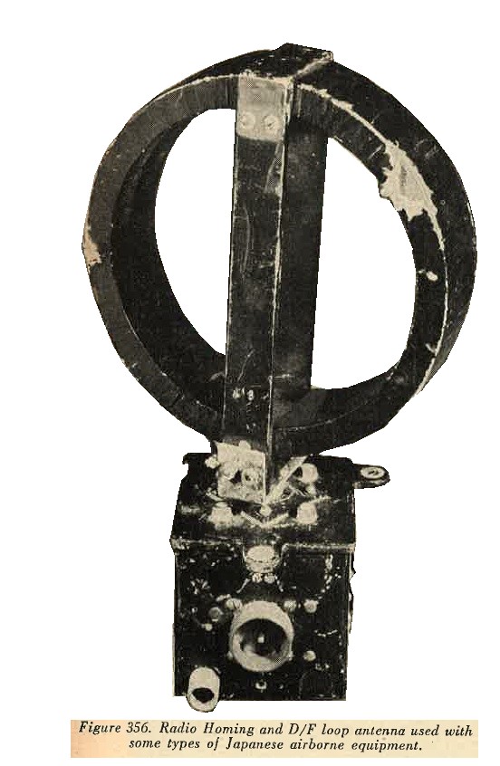
Figure 356. Radio homing and D/F loop antenna used with some types of Japanese airborne equipment. |

Figure 357. Dynamotor power supply for transmitter of Model 96 Type 3 airborne radio set. Used in Type 1 medium bomber (Betty). |
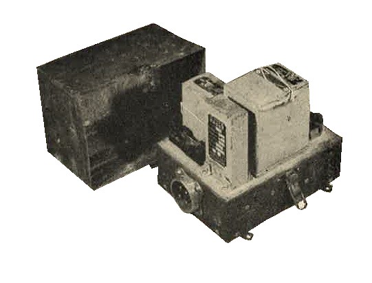
Figure 358. Vibrator power supply for receiver of Model 96 Type 3 airborne radio set. Used in Type 1 medium bomber (Betty). |
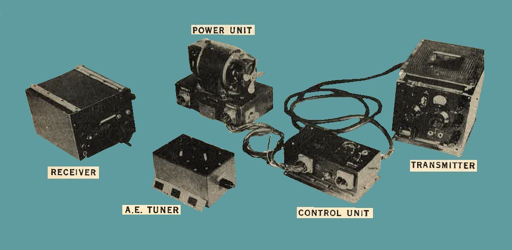
Figure 359. Model 99 (1939) Type 3. Transmitter-receiver. used in single seater fighter (Oscar). Transmitter: 2,500 - 5,000 KC. Receiver: 1,500 - 6,700 KC. Transmitter and receiver crytal controlled. Photo shows complete complements of equipment. |
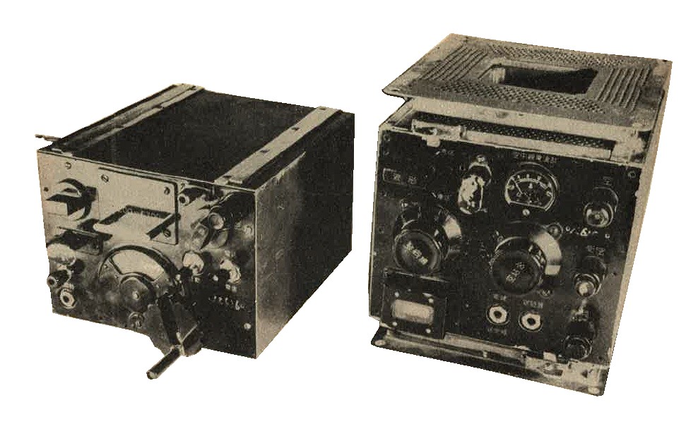
Figure 360. Model 99 (1939) Type 3. Transmitter - receiver. Close up pictures of transmitter(right) and receiver (left). |
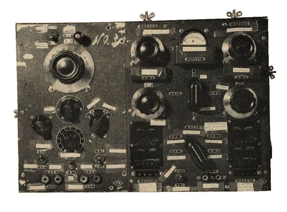
Figure 361. Model 96 (1936) Type 1. Trnasmitter/receiver Model 13, from Mitsubishi bomber. Transmitter; 7,600 - 10,600 KC Receiver: 7,500 - 10,800 KC |
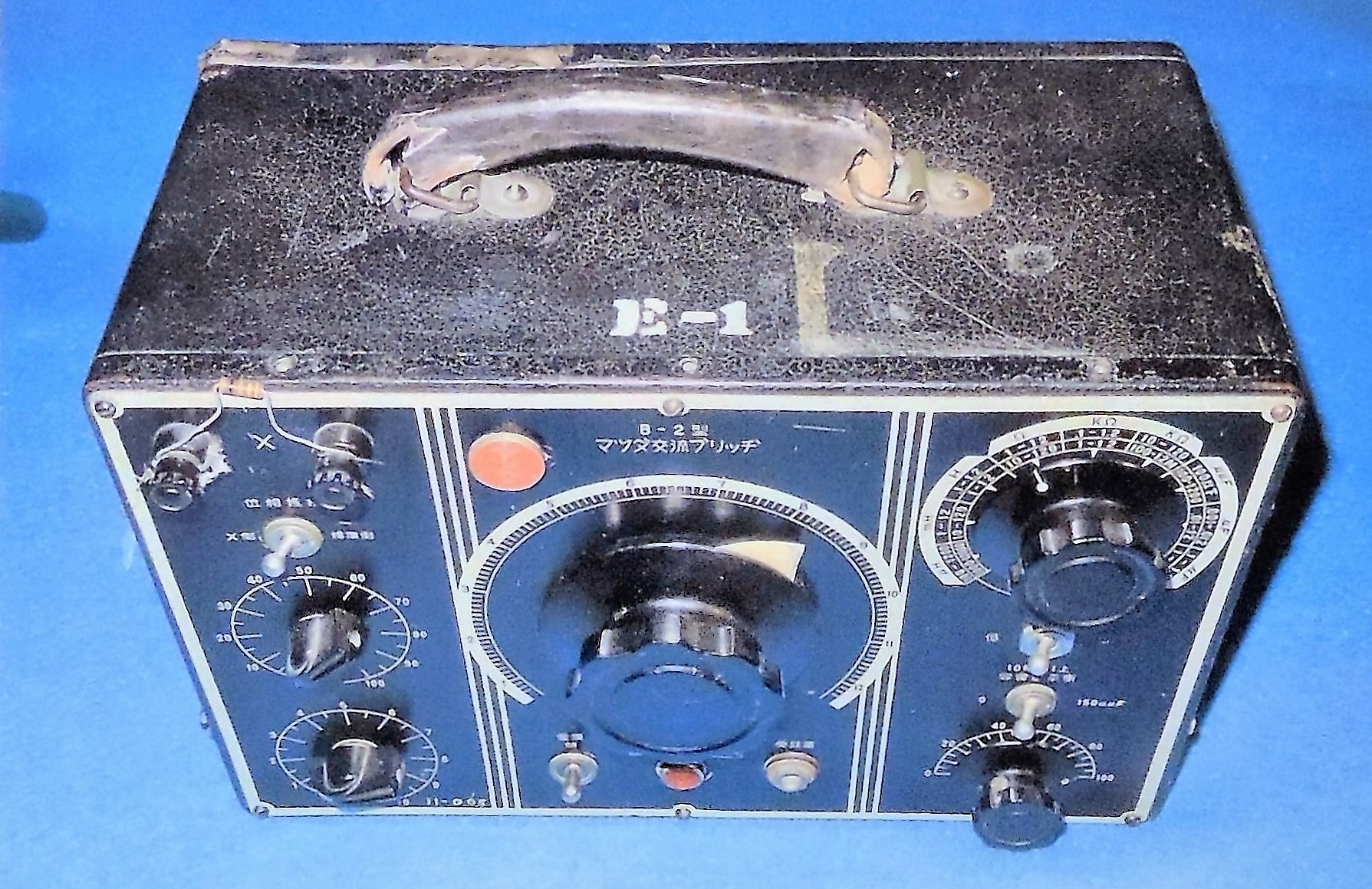
Figure 361. WWII Japanese frequency meter. |
3. WWII JAPANESE TELEPHONES
a. WWII Japanse Model 92 (1932) telephone.
This telephone (Figure 364) is of conventional design and normally is used on a ground return circuit, although it may be used also on a metallic circuit. It is equipped with a buzzer and key arrangement for sending code. The complete unit is encased in a metal-reinforced, wooden box, approximately 12 inches long, 5 inches wide, and 7 inches high.
Directly beneath the aluminum cover is a transmitter, handset receiver, extra single ear phone, and the buzzer key. Permanent lead-in wires are fitted to the telephone to which the field wire is attached. Current is supplied by a hand-cranked generator which generates ringing current rated at 55 volts A.C. It is not advisable, therefore, to use this set with U.S. Army generators which deliver up to 90 volts A.C. It will, however, receive and transmit clearly over U.S. Army circuits, being equipped with two 1 1/2 volt dry cell batteries which furnish 3 volts when connected in series.
These batteries normally are connected in parallel and are stored on a metal rack inside the cabinet. Compared with Allied standards, the gemeral mechanical construction of teh set is inferior. It has been found that the hand switch on the handset receiver causes frequent cut outs as well as noise during operation.
The set is contained in a heavy leather carrying case and may be carried easily by one man. A new carrying case, composed of layers of rubberized canvas, also has been observed. This material will withstand tropical climate much better than leather. The complete set weighd approximately 12 pounds.
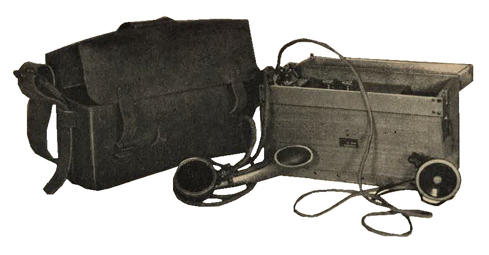
Figure 364. WWII Japanese Model 92 field phone. |
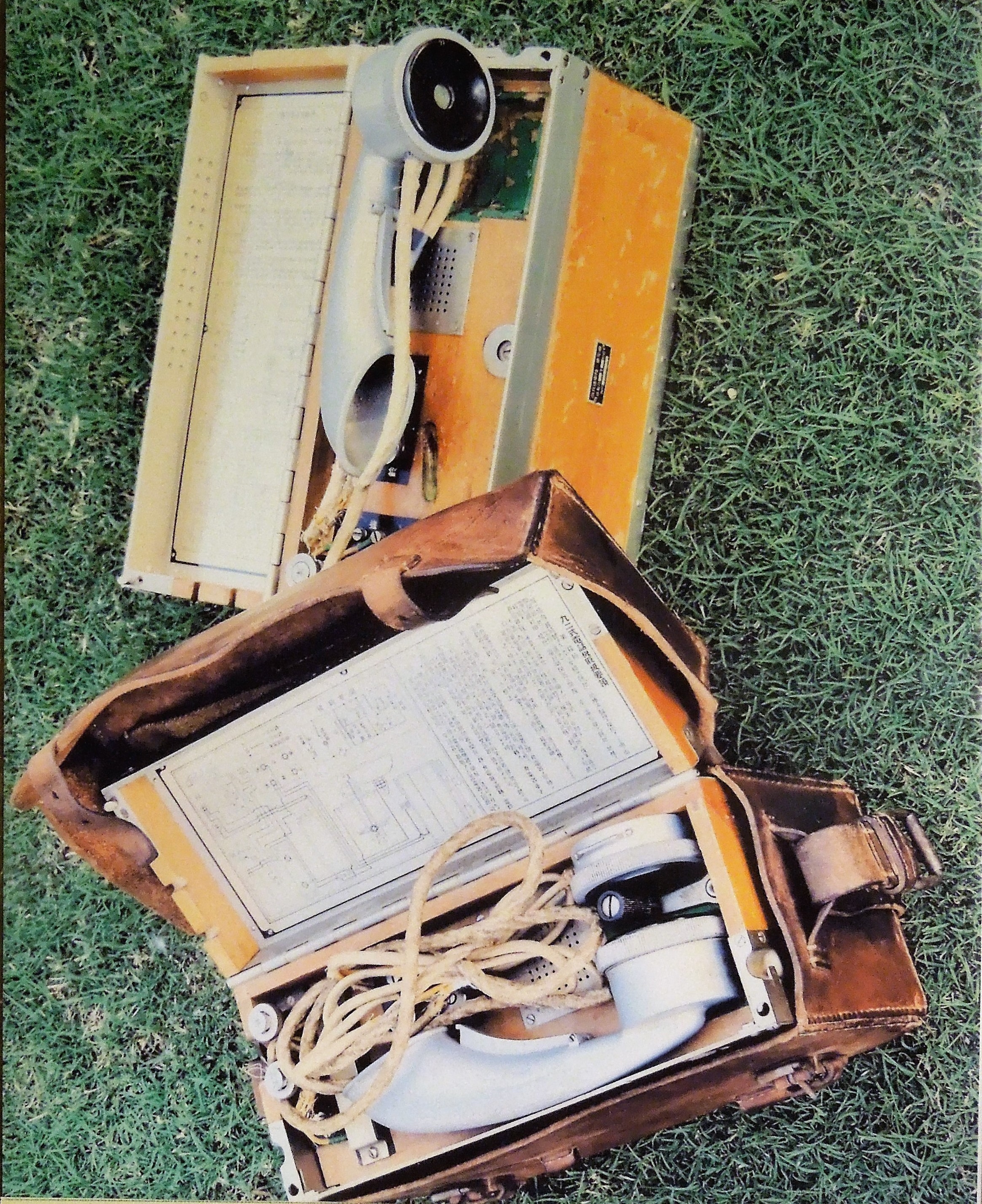
Figure 364-a. WWII Japanese Model 92 field phones. |
b. WWII Japanese Model 2 (1942) trench telephone.
This telephone (Figure 365) normally is used with a ground return circuit, although it may be employed with a metallic circuit. The unit ios contained in a wooden cabinet, with metal-reinforced corners. The handset; batteries; and generator, belt, condenser, and induction coil are housed in three compartments.
The set may be operated on local or common battery circuits, while magneto signaling facilities also are included. The generator hand crank folds up and fits within the generator armature shaft. A fiber driving gear on the generator eliminates noise to some extent during cranking.
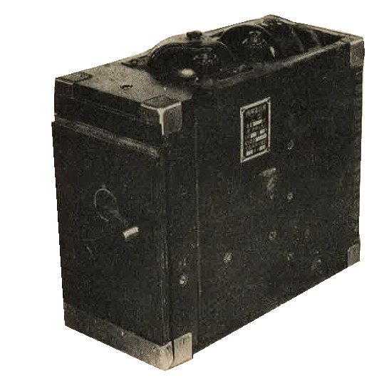
Figure 365. WWII Japanese Model 2 trench telephone.
c. WWII Japanese Sound-powered telephone.
The microphone (Figure 366) of the sound powered telephone, deriving its energy directly from the sound waves, is a reversion to the original principle of the telephone in that the receiver unit is used also as a microphone. The instrument consists of a handset, with a single dual purpose operating unit and an additional unit as an extra receiver.
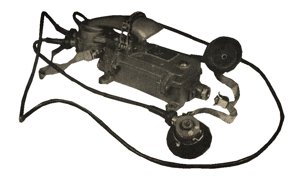
Figure 366. WWII Japanese complete assembly of sound powered telephone.
It is used to provide intercommunication within vehicles, or even short lines when circumstances require rapid and simple setting up and disconnection.
d. WWII Japanese Lip microphone.
This carbon type microphone is attached to a leather and elastic strap. Total weight is approximately 3 1/2 ounces. Other than the fact that it is used with head receivers, there is nothing to indicate for what purpose it was intended. However, since the output of this microphone is low, it is possible that it may be used in connection with radio equipment in armored vehicles.
4. WWII JAPANESE SWITCHBOARDS
The Japanese have field switchboards, but in place of these they frequently connect field telephones together to form a party line system. At higher headquarters and large air fields commercial switchboards and pole lines of open wire construction have been used.
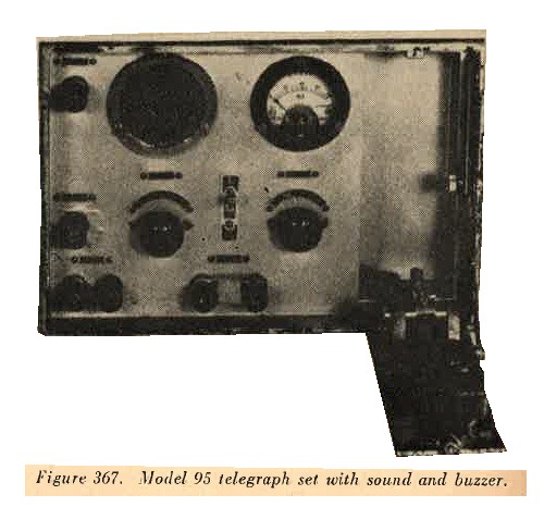
5. WWII JAPANESE MILITARY TELEGRAPH SETS.
Figure 367 illustrates the Model 95 set which can be used in conjunction with Model 92 telephone. The set has built in key arrangement. It probably is used by lower units for administrative traffic.
6. WWII JAPANESE MILITARY SIGNAL LAMPS.
a. WWII Japanese Portable signal lamp. This lamp, provided with universal adjustment, is mounted on a tripod and powered by a hand generator. At the front, a hinged cover, equipped with a shutter adjustable to 6 degrees, controls the intensity of light. A reflector and 6-volt lamp, rated approximately 32 candlepower, are contained inside the housing. Usually 3 different colored filters - are provided with each lamp. A metal reinforced wooden cainet, 10 3/4 inches long, 5 3/8 inches high, and 8 3/8 nches wide, is provided for the equipment with the exception of the generator.

Figure 368.
A - Signal lamp
B - Key with lock device
C - Carrying case with spare lamp, eyepieces, filters, etc.
D - Filters; red, amber, green
R - Hand Generator
b. WWII Japanese military Hand signal lamp. This small pocket lamp measures 3 1/2 inches long. While resembling a cylindrical flashlight, it contains no batteries; instead, a cord, connected to an external battery, passes through the hollow wooden handle. The 3.5 volt bulb and reflector are of conventional design. Installed in front of the bulb is a glass filter, divided into red, blue, amber, and clear sectors. A cover, in front of the filter, can be revolved so that its opening will disclose a lighted segment of the desired color.
Signaling is accomplished by a combination push button and slide switch on the side of the case. This lamp should be useful at short range, but the drgree of security would be limited by the fact that its beam is not highly directional.
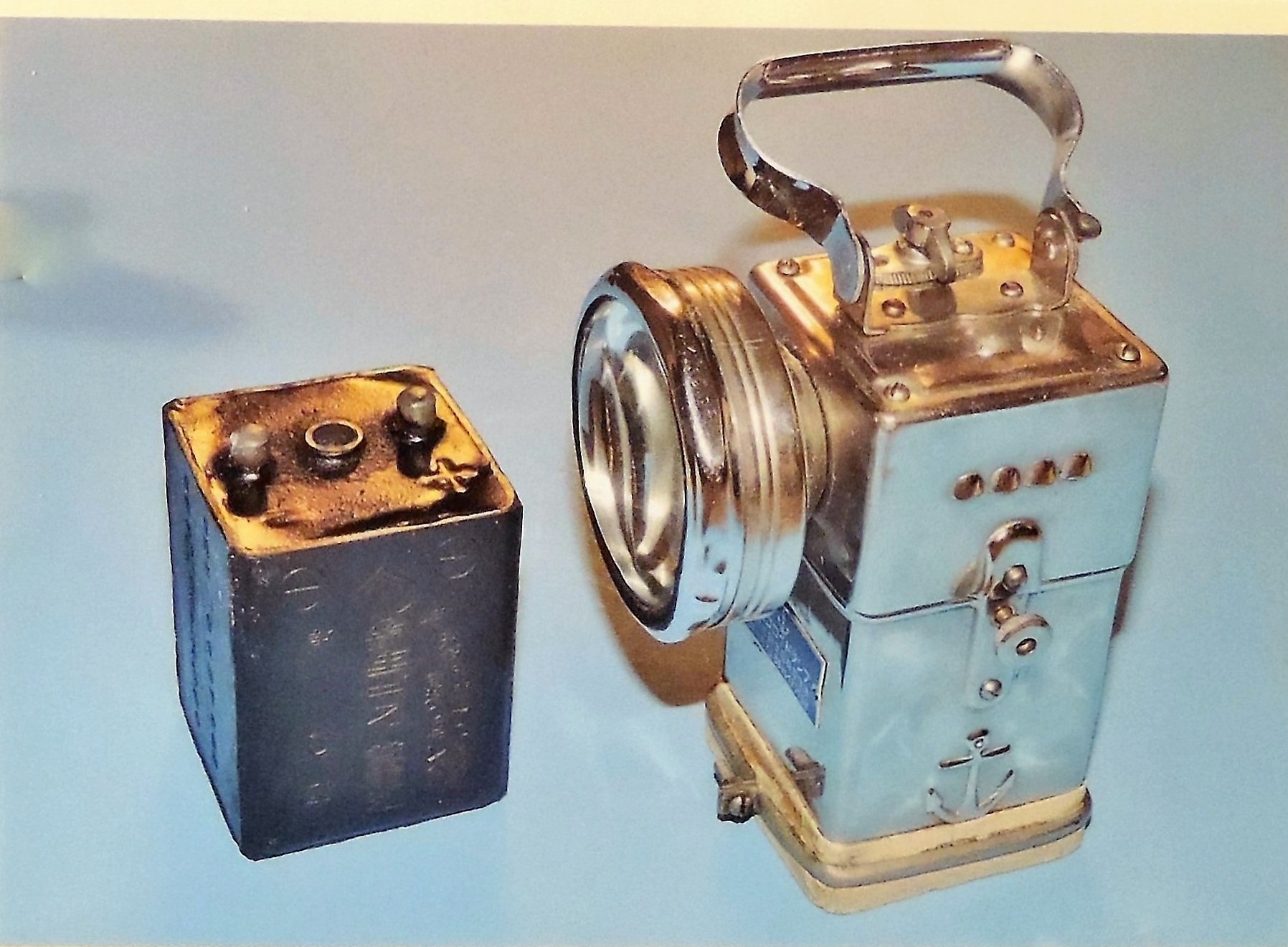
Figure 368-a. WWII Japanese Signal lamp with battery. |
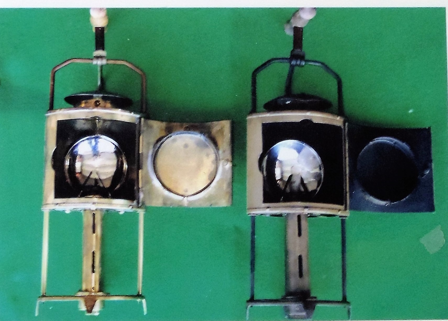
Figure 368-b. WWII Japanese Signal lamp. |
Figure 368-c. WWII Japanese Signal lamp with carrying box and battery. |
Figure 368-d. WWII Japanese early Signal lamp with carrying box and contents. |
7. WWII JAPANESE FIELD WIRE.
The three principal types of field wire in general use are as follows:
a. WWII Japanese Military Assault wire.
Assault wire is very small in diameter. It consists of a single conductor and is composed of 8 strands (1 copper and 7 steel) with an outer covering of yellow colored braid. This wire is for ground return circuits and is used between regiments and forward units.
b. WWII Japanese Military Seven-strand wire.
This single conductor, 7 strand wire (3 copper and 4 steel) is larger in diameter than assault wire. The wire is rubber insulated, and tests have shown that the insulation resistance can remain high throughout a 14-day immersion period. It has an outer covering of Yellow colored braid. Tensile strength of the wire is high, but its abresion resistance is low, and its electrical characteristics are not as good as indicated by its construction. This wire is for ground return circuits and is used between regimantal and battalion headquarters.
c. WWII Japanese Military Heavy wire.
Heavy wire, consisting of two ruber-insulated, solid conductors (one black, the oher red), is used for metallic circuits, probably between division and higher headquarters as well as at the larger airfields. It has an outer covering of green colored braid.
8. WWII JAPANESE MILITARY CABLE.
Different types of cables are used by the Japanese for various purposes. Figure 369 and Figure 370 show types used and their characteristics.
| Outside diameter (inch) | Cross section of cable | 1 | 2 | 3 | 4 | 5 | 6 | 7 | 8 | 9 | Remarks |
| 7/16 |  |
Rubber insulation | Rubber insulation | Cotton string wrapping | No. 14 stranded wire | ----- | ----- | ----- | ----- | ----- | This was taken from the power cord of a test lamp. It corresponds to ordinary rubber covered lamp cord. |
| | |||||||||||
| 7/16 |  |
Wooven steel wire sheath (lead) | Impregnated cloth | Impregnated paper | Lead sheath | Cotton cloth wrapping | Rubber insulation | Copper wire core | ----- | ----- | The conductor of this cable consists of 19 strands of No. 20 copper wire. Probably used as buried underground cable. |
| | |||||||||||
| 7/16 | 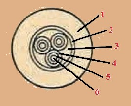 |
Lead sheath | Cotton cloth | Jute of hemp cord filler | Silk cloth | Rubber insulation | Solid copper wire | ----- | ----- | ----- | Each of the three conductors is composed of 17 solid copper wire. |
| | |||||||||||
| 7/16 | 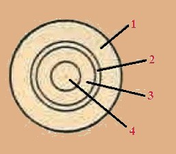 |
Lead sheath | Cotton cloth | Rubber insulation | Stranded copper wire | ----- | ----- | ----- | ----- | ----- | This was taken from a Japanese radar transmitter and was used to carry power to the tube filaments. The single conductor core consists of 30 strands of No. 20 copper wire. |
| | |||||||||||
| 3/8 | 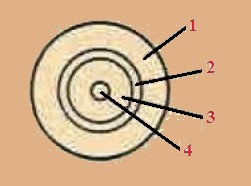 |
Lead sheath | Cotton cloth | Rubber insulation | Solid copper conductor | ----- | ----- | ----- | ----- | ----- | This was used to carry 600 volts to a radar transmitter. The solid copper conductor is size No. 14. The estimated impedance of the line is 100 OHMS. The capacitance of the cable has been decreased by extruding three holes in the otherwise solid rubber dielectric. These holes are in a symmetrical position around the center conductor. |
| | |||||||||||
| 9/32 | 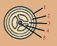 |
Black cotton cloth | Woven steel wire sheath | Rubber insulation | Air holes in rubber | Solid copper conductor, size No. 23 | ----- | ----- | ----- | ----- | The cloth covered coaxial line is used to carry video and pulse signals between the various units of a radar. |
Figure 369. Anatomy of Various types of WWII Japanese cables (Radio communications, radar, etc).
| Outside diameter (inch) | Cross section of cable | 1 | 2 | 3 | 4 | 5 | 6 | 7 | 8 | 9 | Remarks |
| 1 1/4 | 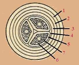 |
Tar coated hemp | Spiral steel sheath. Wound hand. |
Impregnated fiber | Lead sheath | Impregnated paper | Impregnated paper | No. 10 solid copper wire | 15 conductors of No. 17 solid copper wire | ----- | This cable is probably used as underground power cable. |
| | |||||||||||
| 1 1/16 | 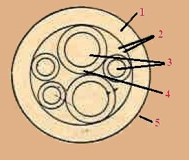 |
White rubber insulation | Cotton string filler | 4/16" diamter stranded from No. 31 tinned copper wire | Rubber insulation | Rubber insulation for H.V. | No. 9 stranded wire from No. 30 tinned copper wire | ----- | ----- | ----- | This cable is probably used to carry power from a power supply unit to a communications transmitter. The large wires are the filament power and the small are for B plus and bias voltages. |
| | |||||||||||
| 2 9/32 | 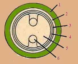 |
Lead sheath | Brown paper | Copper sheath | Brown paper | Polystyrene spacers every inch | Copper No. 9 wire (solid) | ----- | ----- | ----- | The shielded balanced wire line is used to carry power to the antenna of a Japanese radio. Navigation aid. The characteristic impedance of the line is approximately 115 OHMS. |
| | |||||||||||
| 1 1/16 | 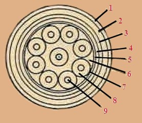 |
Woven wire (white) Steel sheath |
Impregnated cloth | Impregnated paper | Lead sheath | Cotton cloth | Jute or hemp cord filler | Silk cloth winding | Rubber insulation | Solid copper conductor | This is a nine conductor cable. Probably multi-conductor remote control cable. All the conductors are size No. 17. |
| | |||||||||||
| 1/2 | 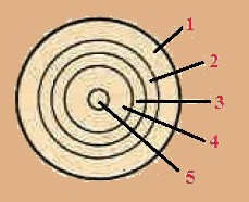 |
Lead sheath | Cotton cloth | Black rubber insulation | White rubber insulation | Stranded copper | ----- | ----- | ----- | ----- | This high voltage cable was used on a radar transmitter to carry plate voltage at a potential of 6 KV. The stranded core, which is size No. 11 is made up of seven strands of No. 20 copper wire. |
| | |||||||||||
| 7/16 | 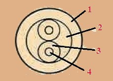 |
Rubber insulation | Cotton string filler | Rubber insulation | No. 16 stranded copper wire | ----- | ----- | ----- | ----- | ----- | This is probably ordinary power cable. |
Figure 370. Anatomy of Various types of WWII Japanese cables (Radio communications, radar, etc).
9. WWII JAPANESE MILITARY WIRE REEL UNITS.
The Japanese use various types of hand wire reel units, most of which appear to be designed primarily for handling single conductor wire.
a. Hand wire reel unit.
The reel is carried on the shoulders, or to one side of the body, by means of a broomstick handle and it will hold approximately 1,600 feet of the larger diameter, yellow braided, field wire. No crank is provided for convinient recovery of the wire. Perforations on the head and splines of the drum tend to damage the insulation if the wire is stored on the reel for any length of time. This unit, which is light in weight and not very rugged, can readily be dismantled without the use of tools. (See Figure 371).
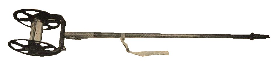
Figure 371.
WWII Japanese Hand wire reel unit with broomstick handle.
b. Head wire reel.
The unit (See Figure 372) is solidly made of pressed metal, with leather straps for carrying on the chest or back, This reel evidently is designed for use by troops in forward areas and normally is carried on the back to allow free use of the hands. (See Figure 372). When revovering wire for which purpose a handle is provided, the reel normally is carried on the chest. The reel may be folded up when not in use.
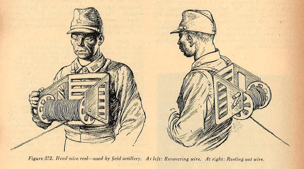
Figure 372. Head wire reel - Used by field artillery. At left: recovering wire. At right: reeling out wire.
10. WWII JAPANESE AIRPLANE PANELS.
clopth air-ground panels are usually 1 1/2 to 3 feet wide and 6 1/2 to 13 feet long. Some shorter panels, and some triangular panels 3 to 6 1/2 feet on each side, have been used. In most cases panels are white, but other colors, comtrasting to the terrain, also may be used.
When regular panels are not available, rags, maps, or pieces of paper may ve substituted. On occasion, Japanese soldiers have been observed to lie on the ground to form panelsignals.
11. WWII JAPANESE MILITARY SIGNAL FLAGS.
Two small hand flags, one red and the other white, are used for semaphore. For signaling Morse Code a large red and white flag, on a bamboo shaft about 5 feet long, is utilized.
12. WWII JAPANESE MILITARY DOGS.
Trained dogs, used to some extent for carrying messages, are cared for and trained by the division signal unit.
13. WWII JAPANESE PIGEONS.
Pigeons, also, are used for carrying messages.
14. WWII JAPANESE MILITARY HAND GENERATORS.
a. WWII japanese Model "F" generator.
This simple and compact hand driven generator, which weighs only 16 pounds, delivers 24 watts. It serves as a source of filament voltage (3 volts) and of plate voltage (125 volts). The mechanical transmission between driving handle and armature consists of 4 geared wheels, 2 of which are fiber, the other steel.
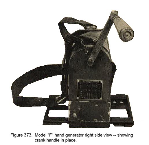 |
According to the name plate, the normal rate of turning is 70 revolutions per minute, giving an armature speed of 5,200
revolutions per minute.Harness is provided for carrying the generator and for fastening it to a support. It is possible
for a man to work the generator when the straps are slipped over his shoulders, with the base resting against his
chest.
Figure 373. Moel "F" hand generator right side view -- showing crank handle in place. |
15. WWII JAPANESE MILITARY BATTERY CHARGER.
Two charging circuits are provided. One uses a Tungar, half-wave rectifier, delivering 14 volts at 6 amperes. The other circuit uses a Type 83, mercury vapor, full wave rectifier, delivering 150 to 160 volts at 0.1 ampere. Component parts are mounted on an angle iron framework which fits into a metal carrying case. The case is provided with ventilatingapertures, 3 weatherproof receptacles, a door at the rear, and a leather carrying handle.
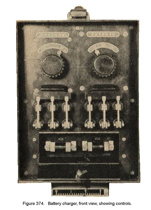 |
The charger is capable of charging one 12 volt storage battery and one storage "B" battery at an average efficiency of 30 percent.
This efficiency compares favorably with that of half-wave Tungar chargers of American manufacture. The switching arrangement
controlling the active turns in the transformerprimaries allows operationof the charge from three different line voltages.
Figure 374. Battery charger, front view, showing controls. |
16. WWII JAPANESE POWER UNITS - DUAL VOLTAGE DC (1300 V / 12 V).
This is a completely self contained, rope starting, power unit, consisting of a single cylinder of 1.977 inch bore x 2.0 inch stroke. The air cooled gasoline engine is coupled directly to a straight shunt, 2 pole field, dual voltage 1300 V/12V generator, inclosed in an aluminum housing. Engine and generator are ruggedly constructed and supported, indicating long-life operation. This unit can be used to furnish plate voltage to U.S. Army SCR 177.
17. WWII JAPANESE MILITARY PYROTECHNIC SIGNALS.
The Japanese make much use of pyrotechnic signals. Projection is achieved by means of Models 10 and 89 Grenade Dischargers, both of which are common infantry weapons.
Listed below ar some of the pyrotechnic signals which can be used in grenade dischargers. They frequently have been referred to by the Japanese as dragons. The nature of he signal may be ascertained by two methods:
(a) by color bands painted on the body
(b) by designs embossed on teh cover (for use in dark).
| NUM | SIGNAL | COLOR BANDS ON BODY | |
| 1. | Black smoke, parachute | --------- | One wide black band. |
| 2. | White star, parachute | --------- | One wide white band. |
| 3. | White star | --------- | One narrow white band. |
| 4. | White star, double | --------- | Two narrow white bands. |
| 5. | White star, tripe | --------- | Three narrow white bands. |
| 6. | Orange smoke, parachute | --------- | One wide yellow band. |
| 7. | Green star, parachute | --------- | One wide green band. |
| 8. | Green star, single | --------- | One narrow green band. |
| 9. | Green star, double | --------- | Two narrow green bands. |
| 10. | Red star, parachute | --------- | One wide red band. |
| 11. | Red star, triple | --------- | Three narrow red bands. |
Signal pistol, 35-mm (1.38 inch) parachute and cluster "stars" in red, white or green colors, with a burning time of from 4 to 15 seconds, are reported to exist. The cartridge closely resembles a shotgun shell. Model 97 (1937) signal pistol; one and three barrel models of this newer type signal pistol have been reported.
The pistol is well made of a good grade of steel with an excellent finish; its overall length is 9 8/16 inches, and its weight is 1 pound 13 ounces.