CHAPTER 9-D2 EQUIPMENT

SECTION V - WWII JAPANESE MILITARY ENGINEER EQUIPMENT.
1. GENERAL.
a. Japanese engineers are well equipped and are armed as infantry. They have shown outstanding ability in both the construction and demolition of bridges. On the other hand, airfields and roads so far encountered have not been up to Allied standards in speed of construction or serviceability. This may be attributed to the fact tha tthe Japanese have depended more on manual labor than on heavy equipment, which they have not taken into forward areas in any quantity.
b. The construction of field fortifications has been very highly developed, and even at remote points Japanese engineers have been successful in constructing first class defense positions from material immediately available. (for detailed description of various kinds of Japanese defensive constructions, see part 2, sections III and IV, chapter 7).
c. Engineers are also well equipped with a wide variety of explosive charges and other material for assault and demolition tasks,
d. The shipping engineers ( Sempaku Kohei ) are specially trained and equipped to operate a large variety of transport craft, including landing barges. (For a chart showing specifications of all known types of Japanese landing craft, see Chapter 8, fihure 157).
e. Pictures and detailed descriptions of certain items of engineer equipment will be found on the following pages.
2. WWII JAPANESE AMPHIBIUOS EQUIPMENT.
a. Bridges.
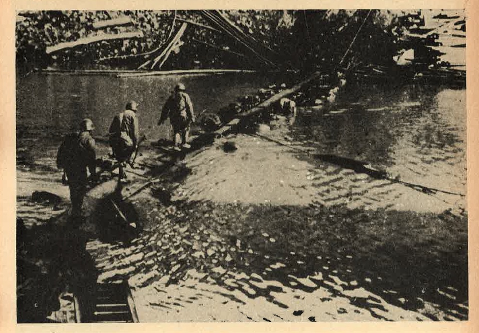
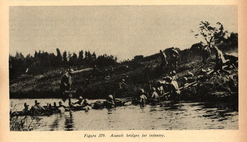
(1) Assault bridges. Several different models have been developed and standardized. Two types are illustrated in figures 379 and 380. one type is made of lengths of steel tubing, supported by bags filled with Kapok. The sections are joined together and afterwards locked. They are light enough to be carried by foot soldiers. Crossing of streams 100 feet and more in width are reported possible with this type of bridge.
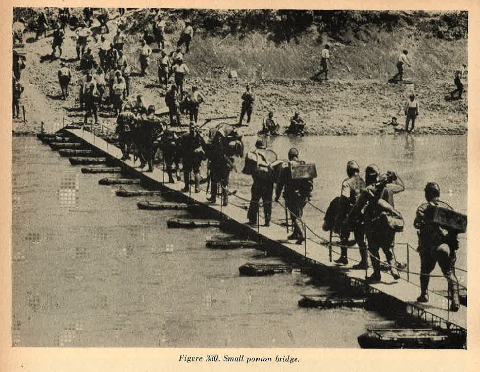
The foot bridge illustrated in figure 380 is supported by floats, each of which can be carried by one foot soldier. This type is for infantry only.
(2) Pontoon bridges. The heavier bridge is suitable for artillery and heavy equipment. The boats which support it are of standard sizes, especially developed for this work. One type, designed for transport by wagon, has 2 bow sections, each 8.7 feet long, and 2 center sections, each 7.1 feet long.
This boat weighs 1,650 pounds complete. An even larger boat of this type, which also comes in 4 sections, is 45 feet long and weighs 6,800 pounds complete. Another type is designed for packing by horses; it has 2 bow sections, each 4.4 feet long , and 3 center sections, each 4 feet long.
The complete boat weighs 921 pounds, and is slightly over 20 feet in length. An even lighter version also exists.
(3) Improvised trestle brisges. The Japanese are skilled in the constructionof wooden trestle bridges (Figure 381) which they erect with greatrapidity from materials prepared beforehand or available locally.
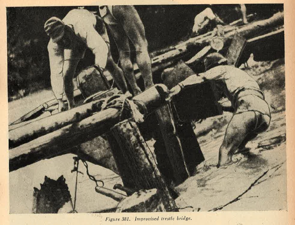
Joints usually are lashed with straw rope, and occassionally are strengthened with iron pins. Such trestles are found serving as approaches to ponton bridges in wide river beds; in shallow rivers they may be several hundred feet in length. Despite their flimsy appearance they are capable of supporting artillery and other heavy equipment.
(4) Sectionalized steel bridges. Prefabricated steel bridges are used by the Japanese, but not as widely as by some other armnies. One truss-construction, portable, steel bridge si 48 feet long and weighs 820 pounds.
b. WWII Japanese Assault boats.
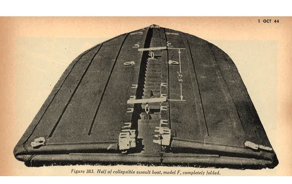
(1) Collapsible boats. Several types of collapsible boats have been developed. One of these, Model F (Figure 382) is am outstanding example of assault boat design, and is very widely utilized.
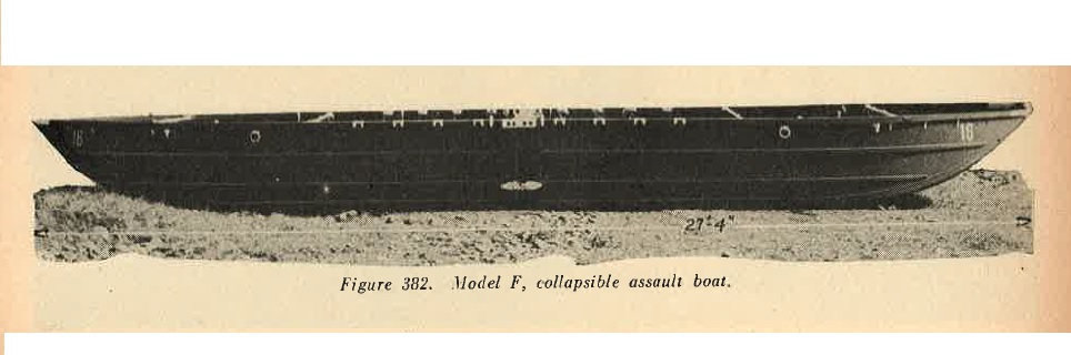
The boat, divided into two sections, each of which collapses flat on itself, (Figure 383) is individually floatable. Each section is 13.6 feet long, 4.75 feet wide, and 2.18 feet high. The wooden frame is braced, and all joints are bonded with rubber. The boat will hold 20 men, and it is estimated that 9 such boats could be loaded flat on a 2 ton truck.
 |
Light outboard motors have been used to propel this boat. Three types of rubber (pneumatic) boats, of from 1 to 10 man capacity, are in use. These are similar in construction to the rubber boats used by other armies. |
(2) Demountable boats. Japanese engineers also operate a variety of demountable motor boats, fitted with outboard and inboard motors of various kinds. One small 30-foot boat breaks into 4 sections and is propelled by an outboard motor. some of the outboard motors are arranged for animal pack. Another larger type breaks into only 2 sections; the stern section is filled with a 4-cylinder, inboard gasoline engine of 30 horsepower. It is not believed that any of these demountable boats permanently mount any weapons.
c. Landing barges.
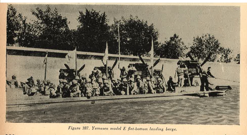
(1) Japanese engineers operate a large variety of landing barges, which have been employed extensively in various theaters. Since Allied air superiority has seriously interfered with Japanese use of transports in many theaters, landing barges generally have been employed foe the supply and evacuation of their forward areas. As many as 500 of these craft have been found congregated in one port.
(2) Some of the design features of these small vessles are of interest. The landing barge screw shown in Figure 384 is designated for operation in shallow waters and affords maximum protection to the screw.
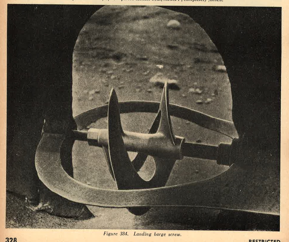
The Japanese generally are credited with the development of he folding ramp, which now is used so extensively.
(3) A typical landing barge is the Daihatsu Model A (Army). The Daihatsu is probably in wider use than any other type; the picture is Figure 385 gives a general ideal of it.
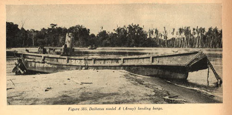
(4) The specifications of teh Daihatsu illustrated in Figure 385 are as follows:
| 1. | Length | --------- | Approximately 49 geet. |
| 2. | Beam | --------- | 11 to 12 feet. |
| 3. | Height | --------- | Approximately 6.5 feet. |
| 4. | Draft | --------- | 3 to 4 feet. |
| 5. | Freeboard | --------- | 1.5 to 2 feet amidships. |
| 6. | Speed | --------- | 6 knots (cruising (10 knots maximum) empty). |
| 7. | Engine | --------- | Diesel, 6 cylinder, 60 to 80 horsepoer, preferred. Some may have heavy oil, electric ignition, or gasoline engines. |
| 8. | Capacity | --------- |
100 to 120 men (short hauls only) 40 to 50 emn on longer trips, or 10 to 15 tons, or 1 light tank (7 to 9 tons), or 1 150-mm howitzer (6 to 7 tons, complete). |
| 9. | Crew | --------- | 5 to 7 men. |
| 10. | Armament | --------- | Not standardized. However, at least two machine guns, or one or two 13-mm heavy machine guns. Fire from 20-mm guns has been encountered from this type, and on several occassions 37-mm guns have been found. |
| 11. | Armor | --------- | A vertical shield of steel, .12 to .36 inch thick, usually protects the coxswain and control gear from frontal fire. Occassionally this type has steel plates, 15 inches by 12 inches, .36 inch thick, hooked to gunwales. |
| 12. | Construction | --------- | Based on standard Japanese fishing boat design, this landing barge has been developed over a long period of years. The metal hull, about .2 inch thick, is of welded steel plate, supported by heavy wooden braces. The twin keels at the bow are of heavier steel and are riveted. The bow ramp is of wood, and teh sides above the waterline are covered with timber. The Daihatsu has an open cockpit in the middle, with a watertight compartment at each end. The engine room at the rear is steel decked. |
This clumsy looking vessel is surprisingly versatile, and will stand a great deal of abuse. Its heavy double keeled bow and protected screw make it very serviceable in shoaly, rock infested waters.
a. Rollers. Various types of road rollers, of small, medium, and large sizes, have been encountered. All are of simple and sturdy design. The small roller shown in Figure 388 weighs about 9 tons and is powered with a Ford Model B, 4-cylinder, gasoline engine. The medium roller shown in Figure 389, about 18 tons in weight, is Diesel powered. Largerrollers also have been captured.
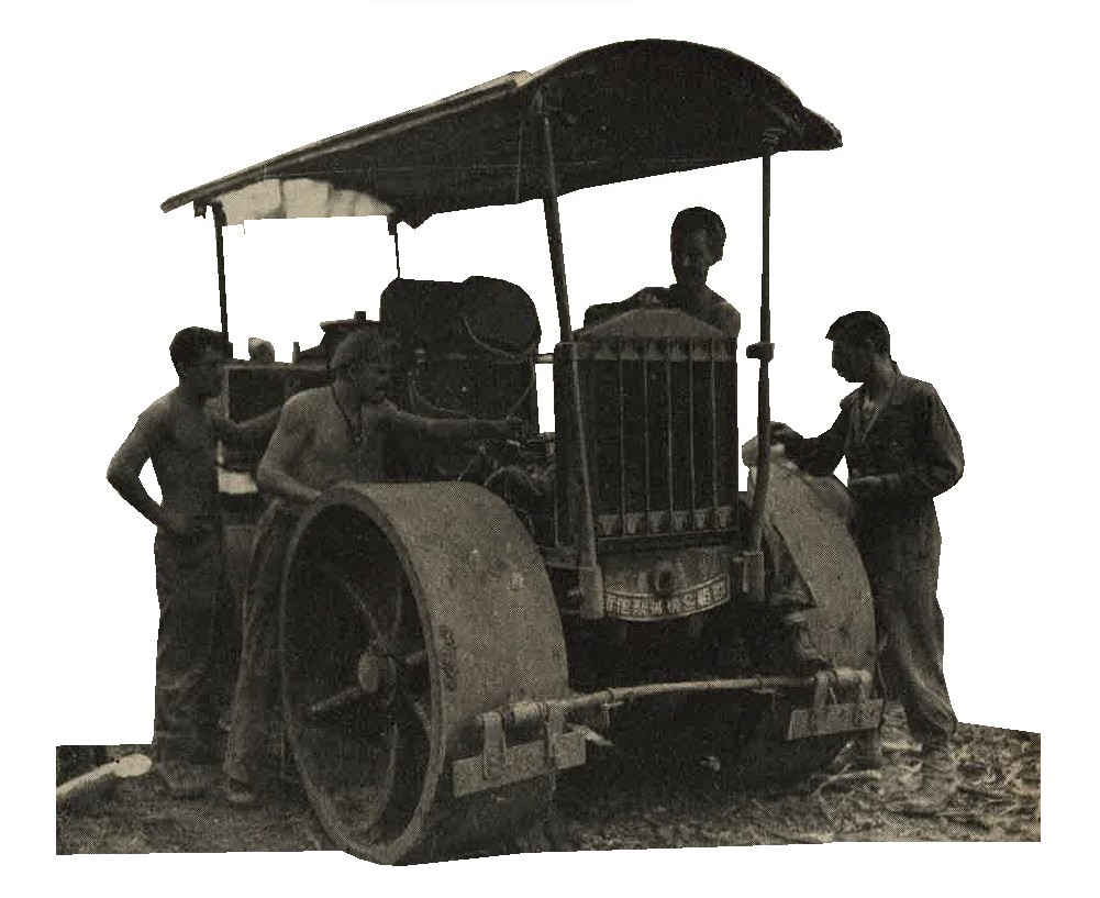
Figure 388. Small gasoline roller.
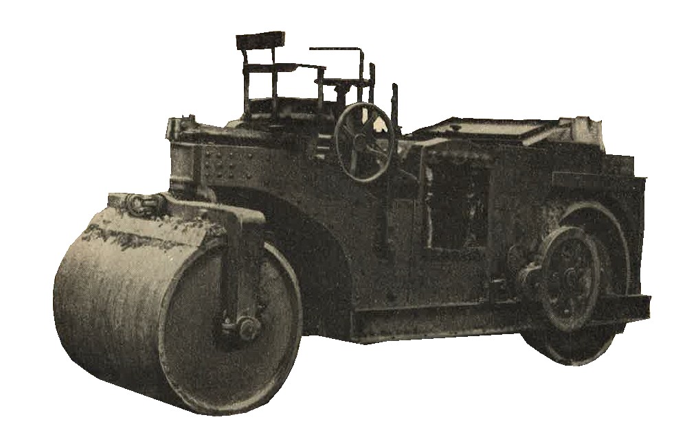
Figure 389. Medium Diesel powered roller.
b. WWII Japanese military Prime movers. For detailed specifications, see Section III of this chapter.
c. WWII Japanese military Power rock crushers. Power rock crushers of rather small capacity, but of good condtruction, have been seen. Power is furnished by small Diesel motors. These rock crushers are found mounted in pairs, usually on a platform.
d. WWII Japanese military Concrete mixers. Portable concrete mixers (Figure 390) of various types have been developed by Japanese engineers. The mixers, some of which are Diesel powered, can be moved easily from one job to another and erected on a platform to facilitate pouring. Some army types are mounted permanently on trucks.

Figure 390. Diesel powered concrete mixer.
e. WWII Japanese military Portable railroads. Japanese engineers make extensive use of portable railroads of various kids. One standardize type has been gauge of two feet. Rails are small in section, weighing about 10 pounds per foot. and are 18 feet in length. They usually are laid for temporary use. Switch sections are prefabricated. Light flatcars, 4 feet wide and 6 feet long are used on this type of portable railroad.
Racks or sideboards can be fitted to give increased capacity to the flatcars. Such light cars can be pushed by manpower, or pulled by small, gasoline powered locomotives.
f. WWII Japanese Mobile power driven saw. The power saw is another piece of Japanese construction equipment used in forward areas, where defenses must be constructed in forward areas, where defenses must be constructed of heavy logs. Power is furnished by a small gasoline motor. In rear areas, larger circular saws, permanently installed and driven by belt from Diesel motors, will be found.
g. WWII Japanese Mobile well driller. The heavy, mobile, power operated well driller is used in favorable terreain. Power is furnished by the truck engine, which drives an air compressor connected with a large compressed air tank.
h. WWII Japanese Miscellaneous construction equipment. A wide variety of miscellaneous equipment for construction of bridges, defense works, roads and airfields has been developed by Japanese engineers. In the forward areas so far overrun, however, main reliance has been placed on labor troops rather than on mobile equipment. Moreover, it is felt that Japanese engineers have not developed prime movers and earth-moving equipment of the heaviest variety. Although medium weight equipment of these categories has been identified.
a. WWII Japanese Electric power units. Electric generating units, both mobile and heavy, usually Diesel powered, are in wide use. They usually are of standard design and are utilized to supply light and power for a variety of purposes. On one island fortress, Diesel powered generator units ranged from 20 to 100 KVA, all 2,300 volts, 3-pahase, 50 cycle. Underground cables led to intermediate transformer vaults, where the current was stepped down to 110/220 volts for consumption by gun turret motors and communications equipment.
Searhlights were DC arc type, with motor generator converters. A large number of battery charging panels served to charge batteries for communication equipment.
b. WWII Japanese Ice plants. Ice plants of varying capacities have been found on several islands occupied by the Japanese. These are well constructed (Figure 391), and some of them have been used by our troops for long periods.
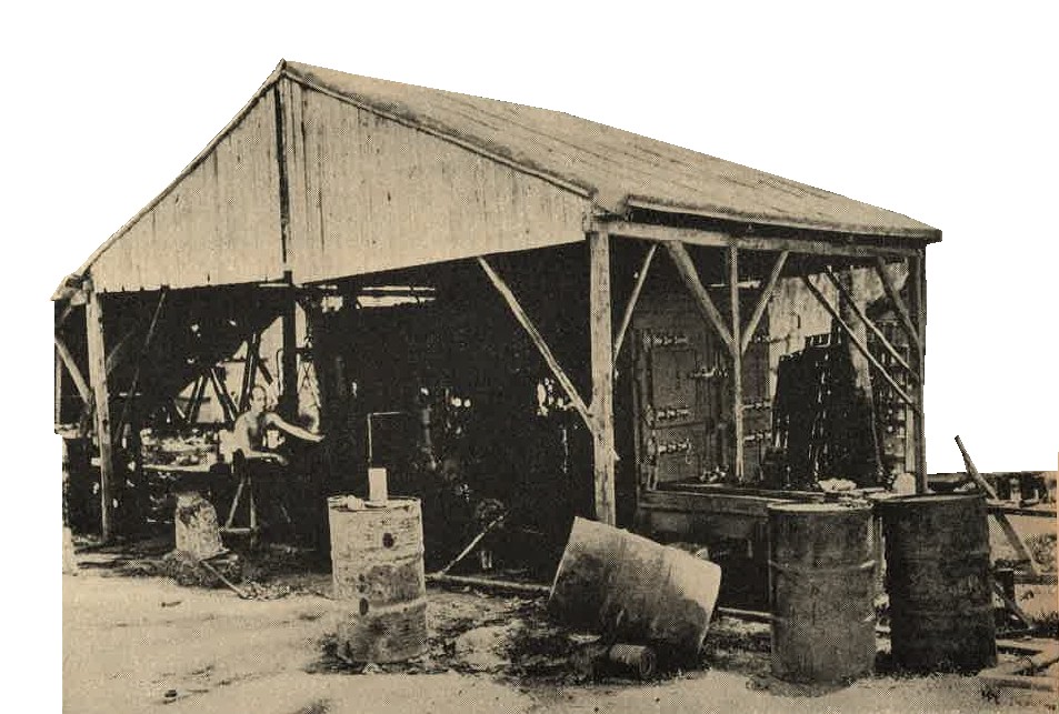
Figure 391. Field ice plant.
Japanese demolition equipment is similar to that of other armies, but unusual attention has been given to small demolition charges employed in assault tasks. Much use is made of picric acid, and serious efforts have been made to preserve this compound from moisture. Plastic explosives also have been used by the Japanese for some time. ALthough electric detonators have been well developed, the Japanese take a very practical view of equipment of this nature, and therefore have retained friction-type igniters in many instances because of their simplicity.
a. WWII Japanese Small demolition charges. In addition to those described in section I, Chapter 9, a variety of small charges, in either block or cylindrical form, are available. Picric acid, TNT, and toluol cheddite (Ammonium perchlorate 76 percent) are used in these charges, some typical specifications of which are as follows:
(1) Block charges.
| 1. | Length | --------- | 2.8 inches. |
| 2. | Width | --------- | 1.6 inches. |
| 3. | Thickness | --------- | 2 inches. |
| 4. | Weight | --------- |
Picric acid and TNT .44 pound. Toluol cheddite .42 pound. |
(2) WWII Japanese Army Cylindrical Demolition charges.
| 1. | Length | --------- | 4.6 inches. |
| 2. | Diameter | --------- | 1.2 inches. |
| 3. | Weight | --------- |
Picric acid and TNT .22 pound. Toluol cheddite .20 pound. |
There are several containers for these small charges. One Zinc can, wired for an electric detonator, has the following specifications:
| 1. | Length. | --------- | 8.2 inches. |
| 2. | Width. | --------- | 2,2 inches. |
| 3. | Thickness. | --------- | 3 inches. |
This can contains three of the block charges mentioned in (1) above and is very widely used.
b. WWII Japanese Army Large Demolition charges. In addition to the bangalore torpedo described in Section IV, much larger demolition charges in this form are unsed by engineers. One large bangalore torpedo consists of 4 sections and a large detonator. Each section contains 10 of the cylindrial charges described in a (2) above. The assembled torpedo is 34 feet long and weighs 225 pounds. Other large charges are assenbled in various forms as needed, with the addition of plastic explosive when necessary.
c. WWII Japanese Plastic explosive. This explosive has the following composition:
| 1. | Cyclkonite | --------- | 80 percent. |
| 2. | Vegetable oil binder | --------- | 20 percent. |
It is issued in rolls, 4 inches by 1.12 inches, each roll weighing .25 pound. These rolls are individually wrapped in parchment and in turn wrapped in a paper package.
d. WWII Japanese military Detonators.
(1) Nonelectric detonators. Several types have been recovered. One very large, non-electric detonator has the following specifications:
| 1. | Length | --------- | 2.7 inches. |
| 2. | Diameter | --------- | 0.3 inch. |
| 3. | Contents | --------- |
Fulminate of mercury - 88 grams PETN - 4 grams. |
This detonator is made of brass.
(2) Electric detonators. There are a number of types and sizes. Model 97 (1937) electric detonator has outer and inner cases, both of brass, and has the following specifications:
| 1. | Length | --------- | 3.25 inches. |
| 2. | Diameter | --------- | 0.27 inch. |
| 3. | Contents | --------- |
Fulminate of mercury ...... 3.93 grams Fulminate of mercury plus a deadening agent ..... 0.28 grams PETN ..... 1.98 grams. |
(3) WWII Japanese Pull igniters.
(4) Several types of slow burning and instantaneous fuzes have been developed. The instantaneous type (Primacord) is protected by a rubber impregnated, hemp thread cover.
Japanese transits, theodolites, map scribers, and reproducers are of good quality and workmanship. In design and development the Japanese have closely followed or even duplicated European or American patterns, and calibraions and markings usually are in Arabic numerals. Allied engineers have no difficulty in making good use of these instruments in the field.
SECTION VI - WWII JAPANESE CAVALRY AND RECONNAISSANCE.
1. GENERAL.
The Japanese have given much thought to the cavalry arm, which is particularly useful in Manchuria and North China. Their specially bred cavalry horses, the get of Anglo-Arabian sires and native mares, average about 14.3 hands (approximately 57 inches). They have proved satisfactory, since they are sturdy, enduing, and relatively speedy.
2. WWII JAPANESE HORSE SADDLES.
| The saddle (weight about 46 pounds with saddle bags, etc.) shows evidence of both English and American design (Figure 392). |
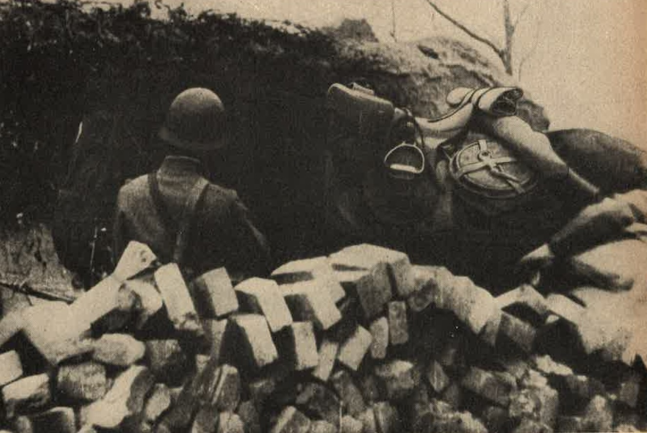
Figure 392. Standard cavalry saddle. |
3. WWII JAPANESE CAVALRY SABER.
|
The saber is a combination of a European type hilt with a Japanese cutting blade. It is 40 inches in length and weighs
3.13. pounds (Figure 393).
The handle is made of wood and has a checkered pattern. A "D" shaped hand guard is present. The scabbatd is painted green and has a drag at the tip. A locking mechanism secures the blade in place. A Brown leather set of straps are attached to the scabbard. They hold the sword in place to the uniform. |
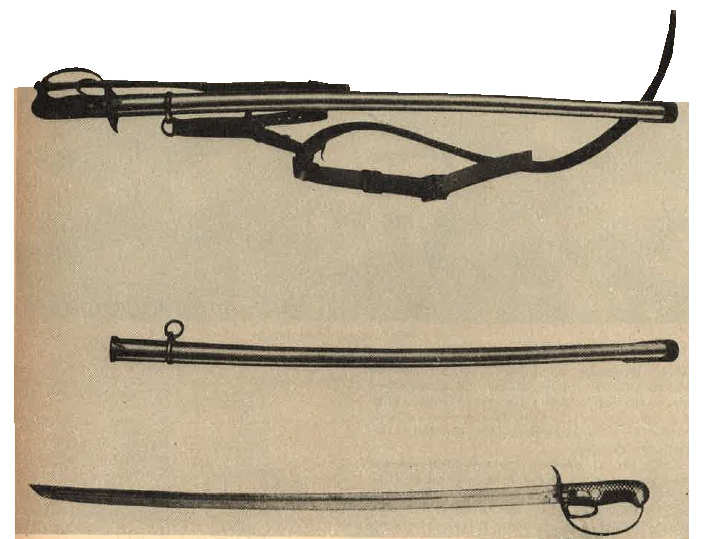
Figure 393. Standard cavalry saber. |
4. WWII JAPANESE MILITARY OTHER EQUIPMENT.
a. The individual trooper carries Model 44 (1911) 6.5-mm cavalry carbine (See section II, Chapter 9). The horse artillery of the cavalry brigade is armed with a 75-mm field gun, which is a variation of the Model 38. It is possible that Model 95 (1935) 75-mm field gun also is used by these units. Light and heavy machine guns are standard equipment of cavalry brigades.
b. The Japanese have formed reconnaissance units which contain both mounted troops and motorized units. In these latter units, tankettes, and possibly armored cars (See section IV, Chapter 9), will be found. Personnel of such units are armed like the horse troops, except that the saber may be omitted.
SECTION VII - WWII JAPANESE MILITARY AUTOMOTIVE AND LAND TRANSPORT EQUIPMENT.
1. GENERAL
a. Although the automotive manufacturing industry was comparatively new in Japan, considerable progress had been made by the end of 1941. Both Ford and General Motors had maintained large assembly plants in Japan proper for many years, and very large numbers of the trucks produced by these plants naturally are used now by the Japanese Army. In addition, very large numbers of European and American motor vehicles were captured by the Japanese in their advance southward.
b. All motor vehicles manufactured in Japan are right-hand drive. They have comparatively high ground clearance and small turning radii. The Diesel is the preferred power unit for heavy vehicles, and many are so fitted. Power weight ratios generally are not good, and tires often are overloaded.
Power take-off systems of various kinds often are found. Hydraulic foot brakes were not installed until recent years; many vehicles still are equipped with mechanical brakes. Because of local regulations, the emergency, or handbrake, is always entirely separate from the main braking system and is mechanically actuated.
c. Because of gasoline shortages, charcoal and wood gas producers began to be installed in 1937. by 1942, all non-military vehicles had been converted to their use, and it seems probable that many military vehicles now operating in Japan proper are using self generating fuel systems.
2. WWII JAPANESE MILITARY PASSENGER CARS
a. Japanese model 95 (1935) 4 x 4 scout car. This lightweight, unarmed, reconnaissance vehicle (Figure 394) was developed after the Manchurian Incident, when the need for an all purpose scout car became pressing. Its air cooled engine offers many advantages for operations in Manchuria and North China, where very low temperatures often are experienced. Initial difficulties with the four wheel drive, particularly with the front universal joints, are believed to have been overcome. Special tires, with heavy rubber lugs, are provided for exceptionally difficult terrain.
|
Specifications:
General:
|
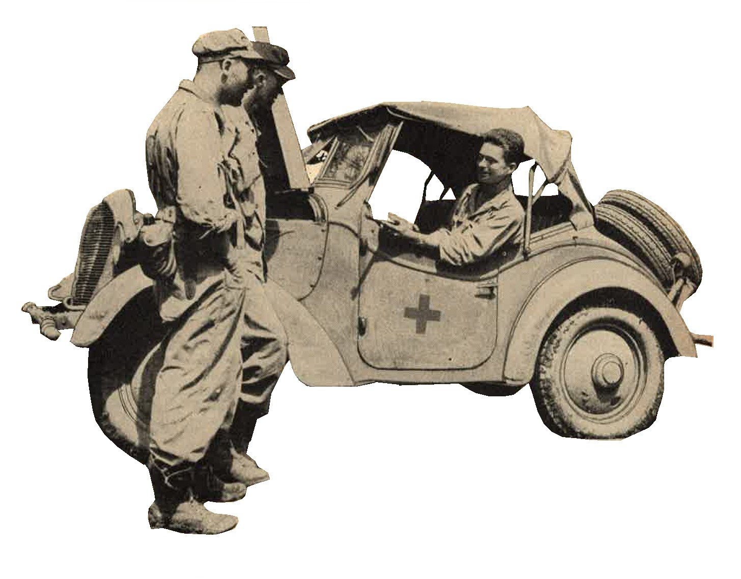
Figure 394. Japanese Model 95 (1935) 4 X 4 Scout car. |
Engine:
|
Chassis:
|
b. WWII Japanese Standard Nissan 5 passenger sedan.
First produced in 1937, the Nissan (Figure 395) has had several modifications, but no major improvements.The design, and the tools to make it, were purchased from the Graham-Paige Company, which designed and tooled up for this model in 1935, but never went into production. The design is not remarkable in any way; from modern standards the power weight ratio is poor.
|
Specifications:
General:
|
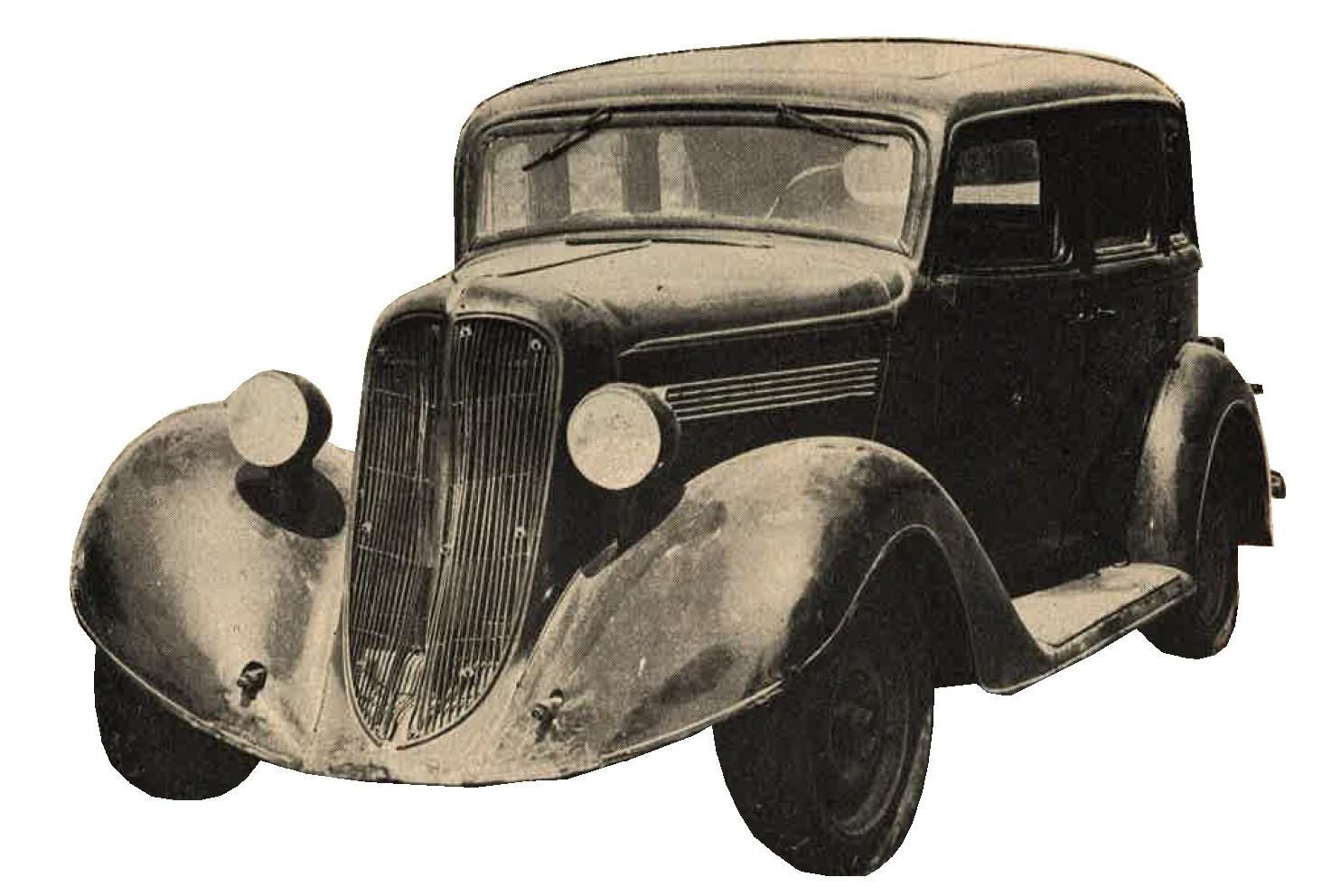
Figure 395. Standard Nissan 5-passenger Sedan. |
Engine:
|
Chassis:
|
c. WWII Japanese military Model 93 (1933) Staff car.
This 6-wheeled staff car (Figure 396) was developed over a period of years. Originally, Hudson and Studabaker chassis were used, but a Japanese chassis ultimately was developed. Available specifications indicate a poor power weight ratio, and a performance not comparable with that of any U.S. command car. However, this vehicle has not yet been reported from the field, and improved models may exist.
|
Specifications:
General:
|
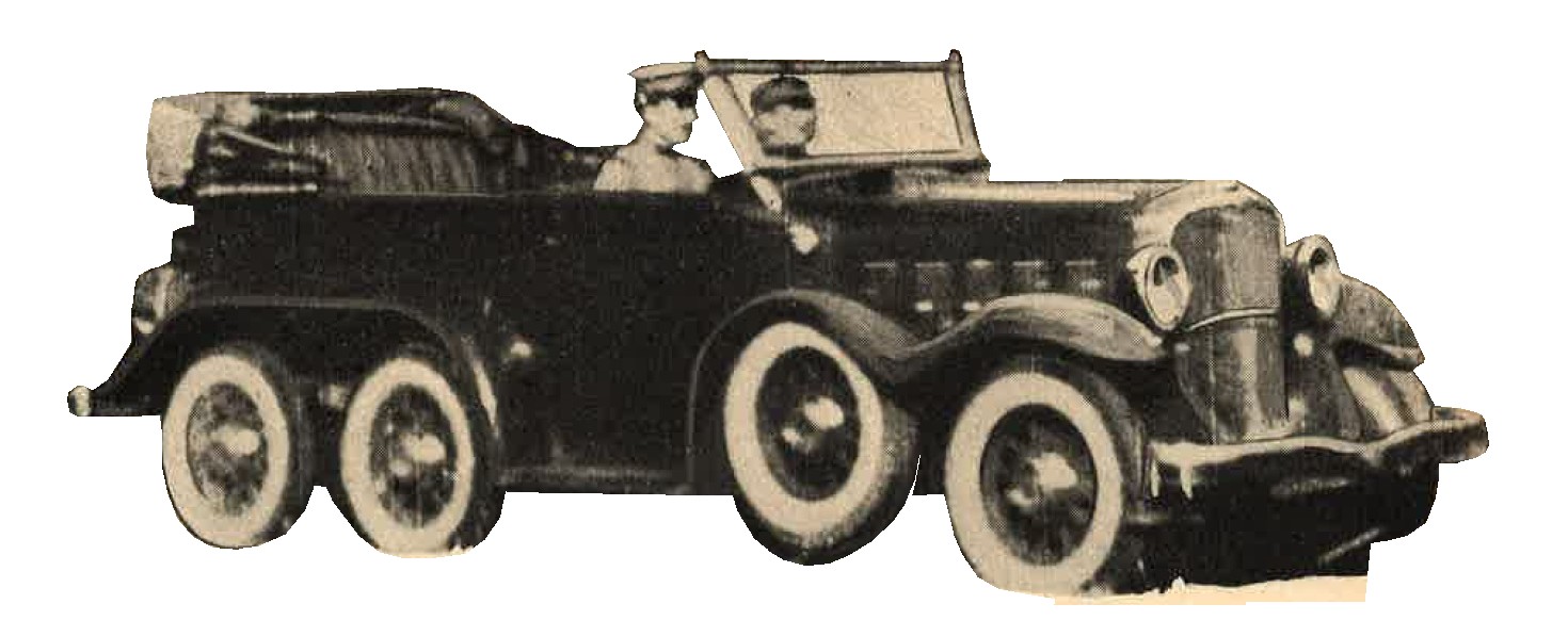
Figure 396. Model 93 (1933) staff car. |
Engine:
|
Chassis:
|
3. WWII JAPANESE MILITARY TRUCKS.
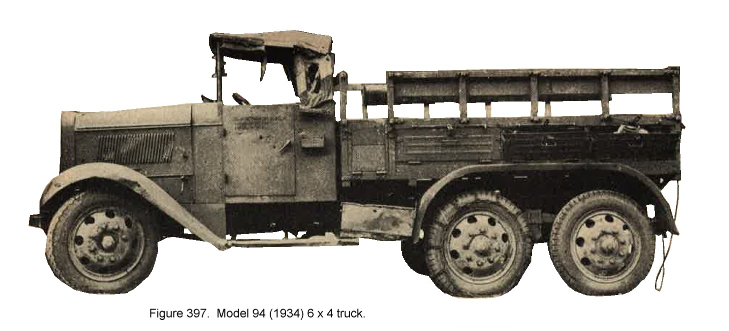
a. WWII Japanese army Model 94 (1934) 6 x 4 truck..
The development of this chassis (Figure 397), in which the rear 4 wheel drive and 2 front wheels only steer, has been progressing for more than 15 years. In recent years an attempt has been made to distribute this vehicle to commercial users, and prior to 1941 a substantial subsidy was paid to private purchasers. Initial difficulties with the final drive now have been overcome, and the vehicle is reliable, although the power-weight ratio is not good. Ground clearance is unusually high and one or more auxiliary transmissions can be fitted. more powerful Diesel engines than those mentioned in the specifications now may be in use. The chassis of the Model 94 is the basic one for the Japanese Army's armored car.
Specifications:
| GENERAL | TYPE A (Gasoline) | TYPE B (Diesel) | |||
| 1. | Weight | --------- | 7,500 pounds | --------- | 8,1870 pounds. |
| 2. | Length | --------- | 17 feet 8 inches. | --------- | 17 feet 8 inches. |
| 3. | Width | --------- | 6 feet 2 inches. | --------- | 6 feet 2 inches. |
| 4. | Height | --------- | 7 feet 4 inches. | --------- | 7 feet 4 inches. |
| 5. | Wheelbase | --------- | 9 feet 2 inches. | --------- | 9 feet 2 inches. |
| 6. | Clearance | --------- | 11 inches. | --------- | 11 inches. |
| 7. | Tread | --------- | 4 feet 11 inches. | --------- | 4 feet 11 inches. |
| GENERAL | TYPE A (Gasoline) | TYPE B (Diesel) | |||
| 1. | Type | --------- | Gasoline, 6 cylinder "L" head (side valve). | --------- | Diesel 4 cylinder. |
| 2. | Horsepower | --------- | 68 maximum. | --------- | 70 maximum. |
| 3. | Bore | --------- | 90-mm (3.54 inches). | --------- | 105-mm (4.13 inches. |
| 4. | Stroke | --------- | 115-mm (4.53). | --------- | 140-mm (5.51 inches). |
| 5. | Displacement | --------- | 4,390 cc (268 cubic inches). | --------- | 4,850 cc (296 cubic inches). |
| 6. | Compression ratio | --------- | 5.25 to 1. | --------- | 17 to 1. |
| 7. | Electrical system | --------- | 12 volts. | --------- | 12 volts. |
| GENERAL | TYPE A (Gasoline) | TYPE B (Diesel) | |||
| 1. | Final drive reduction | --------- | 8.33 to 1. | --------- | 6.75 to 1. |
| 2. | Transmission | --------- | Standard, 4 forward, 1 reverse. | --------- | Standard, 4 forward, 1 reverse. |
| 3. | Brake | ||||
| Foot: | --------- | Mechanical, expanding | --------- | Mechanical, expanding | |
| Hand: | --------- | Mechanical, contracting | --------- | Mechanical, contracting |
b. WWII Japanese Model 97 (1937) Nissan 4 x 2 cab-over engine truck.
The original model, produced in 1937, was a combination of Graham Paige and Japanese designs. The cab-over engine design was adopted because of the narrowness of Japanese roads. The whole front axle assembly proved to be too light, howevwe, and great difficulty was encountered in maintaining the alignment of the front wheels to prevent excessive tire wear. An improved model of more conventional design was finally developed, but a very large number of the original models still are being used by the JapaneseArmy. The power-weight ratio of the Model 97 is not good.
Specifications (104 inch wheelbase model)
General:
|
Engine:
|
Chassis:
| 1. | Final drive reduction | --------- | 6.19 to 1. |
| 2. | Transmission | --------- | Standard, 4 forward, 1 reverse. |
| 3. | Brakes | ||
| Foot | --------- | Hydraulic. | |
| Hand | --------- | Mechanical. |
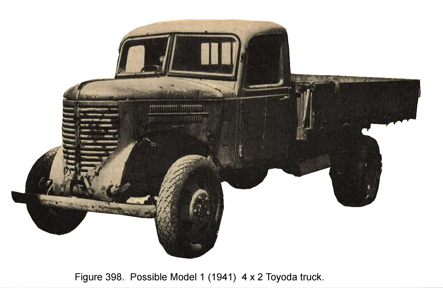
c. WWII Japanese military Model 1 (1941) 4 x 2 Toyoda truck.
After disastrous experiments with a truck of their own design, the Toyoda company finally produced this model (Figure 398), almost an exact copy of the 1939 Chevrolet.
Some manufacturing difficulties have been encountered, and the present power weight ratio is not considered satisfactory.
Specifications:
General
|
 |
Engine:
|
Chassis:
|
4. WWII JAPANESE MILITARY TRAILERS.
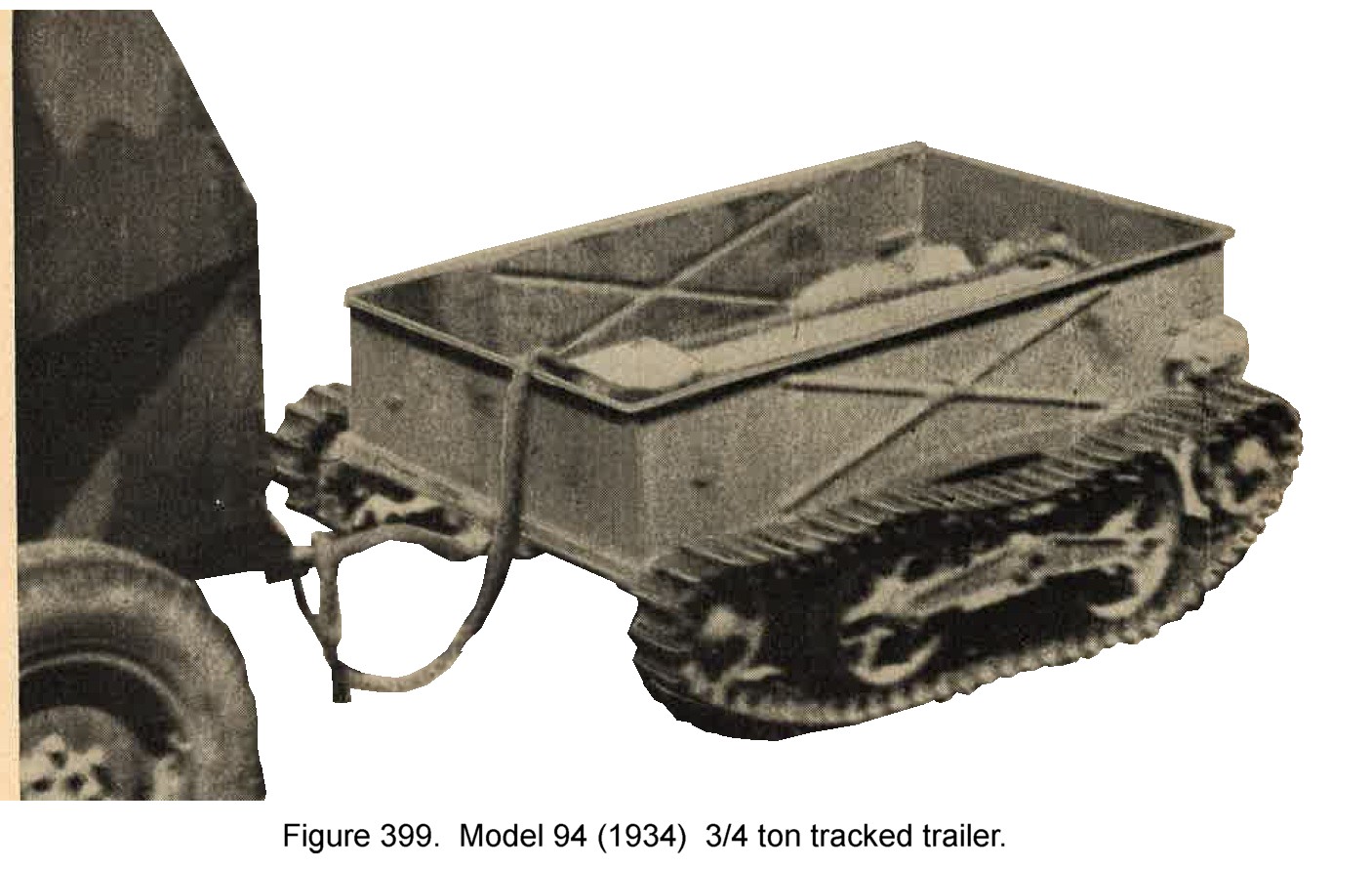
a. WWII Japanese Model 94 (1934) 3/4/ ton tracked trailer.
This trailer (Figure 399) has been designed specially for towing behind the various model tankettes. In China it has been used extensively for transportation of supplies and ammunition. The body of the trailer appears to be of pressed steel construction, and teh suspension consists of 2 bogie wheels with front and rear idlers. Track is similar to that used on the tankette.
b. WWII Japanese military 2-Wheel trailer.
This 2 wheeled trailer (Figure 400) is designed specially for high speed transport. It is of metal construction and is equipped with pneumatic tires.
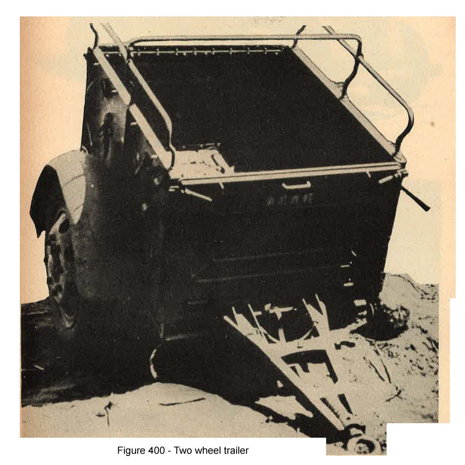
Figure 400. WWII Japanese two wheel trailer.
5. WWII JAPANESE ARMY MOTORCYCLES.
a. WWII Japanese Model 97 (1937) motorcycle.
Japanese military motorcycles (Figure 401) are adaptations of Harley davidson designs. Several models between 1,000 cc and 1,500 cc displacement, have been produced, but it is believed that Model 97 is generally in use. Extra large wheels can be fitted to obtain maximum ground clearance. The design of all types includes provision for a sidecar, which can be fitted with a light machine gun for which at least two different mounts are available. Only minor changes have been made in the original Harley Davidson designs, and peformance is generally satisfactory.
Specifications
General
|
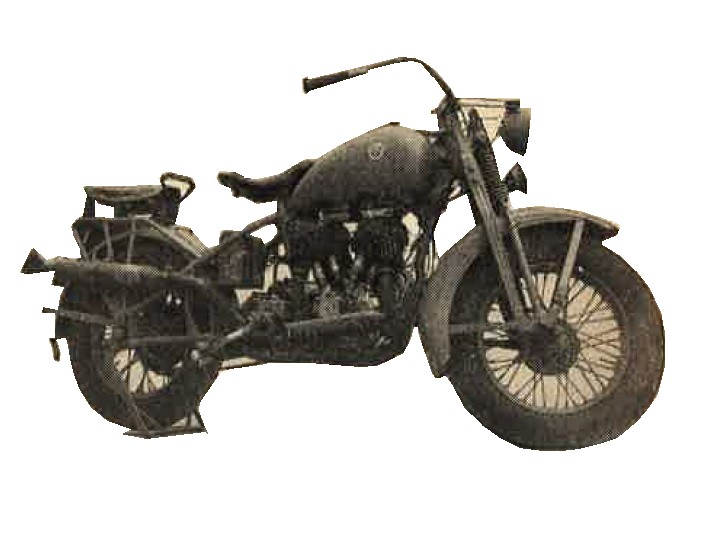
Figure 401. Model 97 (1937) motorcycle. |
Engine
|
Chassis
|
b. WWII Japanese Motor tricycles (Sanrinsha).
The motor tricycle (Figure 402) has been developed as a commercial freight carrier in Japan since 1930. Many commercial versions exist. With engines ranging from 350 cc to 1,000 cc in displacement. Lighter types have single chain drive without differentials, whereas heavuer types may have shafts or double chain drive, with differentials.
Load capacities vary from 300 to 1,000 pounds. A standard three speed transmission, and reverse, is used. It is believed the army adopted whatever types were available, and that no standard army model exists.
|
Lighter tricycles may have had 2 cycle engines, and some 2 cylinder types have been encountered. The ussual
design, however, is chain driven, with a slow speed, single cylinder, 4 cycle engine of about 750 cc
displacement.
Specifications:
|
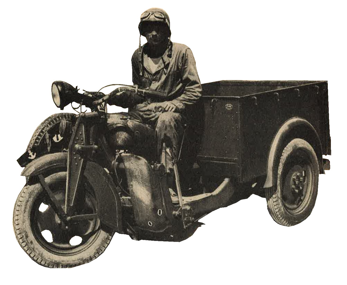
Figure 402. Motor tricycle. |
6. WWII JAPANESE MILITARY BYCICLES.
Japan is one of the world's largest producers of bicycles; in 1940 there were 1,000,000 in Tokyo alone. There is a standard army type, designed along English lines, with front and rear wheel brakes and large wheels. It has been used extensively in the present war.
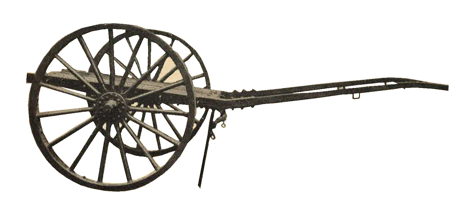
7. WWII JAPANESE MILITARY TRANSPORT CARTS.
The Japanese army employs a variety of hand and horse drawn carts. Several of these are shown in figures 403, 404, 405.
|
Figure 403.
Army transport cart of wooden construction with metal bracing. Characteristics;
|
|
Figure 404. Transport cart designed to be towed by two draft horses. It weighs 765 pounds and has a reported carrying capacity of 825 pounds.
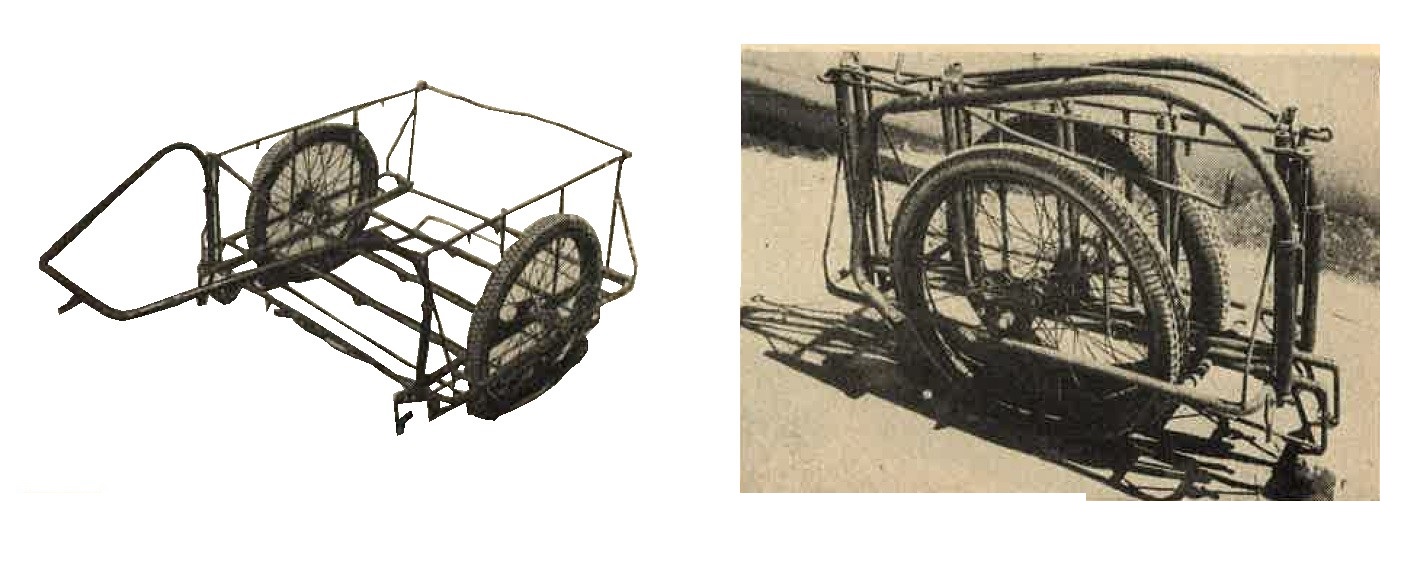
Figure 405. Collapsible hand cart of metal construction weighing 100 pounds. It may be pulled by hand or towed by bicycle.
SECTION VIII - WWII JAPANESE MILITARY TENTAGE.
1. GENERAL.
Although the Japanese excellent octagonal tents, very little use is made of tentage in training or in the field, aside from shelter halt tents. Tents are considered necessary only for medical units and field hospitals, or for troops in regions where other shelter is not available. In inhabited regions, troops are billeted in houses or other buildindgs; in jungles, native huts frequently are built as soon as the situation becomes sufficiently stabilized. The Japanese are unable to improvise shelters in cold barren regions and therefore house large numbers of men in tents. Even there, every effort is made to bring forward building materials in order to get the men from under canvas as soon as possible.
a. WWII Japanese army Octagonal tent.
The octagonal tent ordinarily houses from 15 to 20 men, although the manual states taht 40 can be accommodated in the tropics amd 36 in cold regions (Figure 406).
Pyramidal in shape, it is made of comparatively ligjhtweight, closely woven duck. It is about 24 feet in diameter and uses a 12 foot 9 inch center pole.
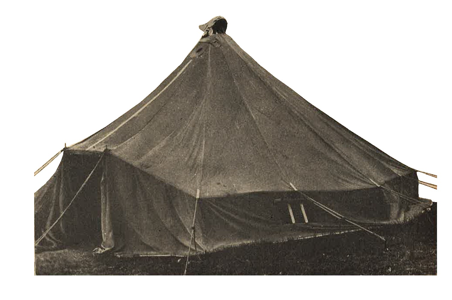
Figure 406. Japanese octagonal tent. (This complete tent weighs 118 pounds, without pegs and poles.
b. Use of the octagonal in cold climates.
(1) In cold regions a second tent of closely woven, strong, white cotton is suspended inside the main tent and held in place by tie tapes. The 6 to 8 inches of air space between the tent and tent liner gives good insulation against the cold, eliminates drafts, and provides a second shelter against moisture. Such a tent may be heated efficiently and economically because of these double walls which also permit the use of dim lights at night without danger of violation blackout discipline.
(2) Two types of stoves are used in these tents, both with grates for burning coal or charcoal. One is a drum stove, 20 to 22 inches in diameter and 24 inches high, with a 6 inch opening in the center of the top for the stovepipe. The second type of stove is cast iron, about 2 feet high, 18 inches deep, and 14 inches wide. Both types cab be broken down to save shipping space.
c. Use of the octagonal tent in the tropics.
The same tent also is used in the tropics, though to a very limited extent, because native type thatch huts usually are considered superior. A mosquito netting takes the place of the inner liner in tropical climates.
SECTION VIII - WWII JAPANESE MILITARY MEDICAL EQUIPMENT.
1. GENERAL.
Japanese military medical equipment is practical, and civilian medical practices have been considered relatively modern.
2. WWII JAPANESE MILITARY FIELD EQUIPMENT.
a. Drugs Many of the drugs dispensed have been discarded in European and American medical circles, and some preventatives examined have been found to be without effect. Very extensive use is made of drugs that have to be injected, and field kits (Figure 407) contain ampoules of a wide variety of sizes and shapes, with no standardization for shipping and packaging. Much use is made of proprietary (patent) medicines, and standard drugs such as quinine, aspirin, and iodine are of course employed. Anti malarials, besides quinine, apparently are being used in increasing quantity. Vaccines and serums are comparable with those in use in other Armies, although there are indications tehre are indications that some of them are not very effective.
Vitamin products are used extensively, in the form of powders, or tablets (both vitamin B and C) as well as in solutions for injections. Even medical kits contain such vitamin tablets.
|
b. Instruments.
A very great variety of instruments are in use. Most of these appear to be only fair in quality, of nickel plated carbon steel instead of stainless steel. The case shown in Figure 408 is heavy, lined with nickel plated copper, and equipped with aluminum instrument racks. The tray can be removed with the instruments in it and used as a sterilizer - a very convenient feature. Blood transfusion kits examined are bulky and fragile, usable only with a system of transfusion discarded some years ago by other armies. No evidence of the use of blood plasma has been found. |
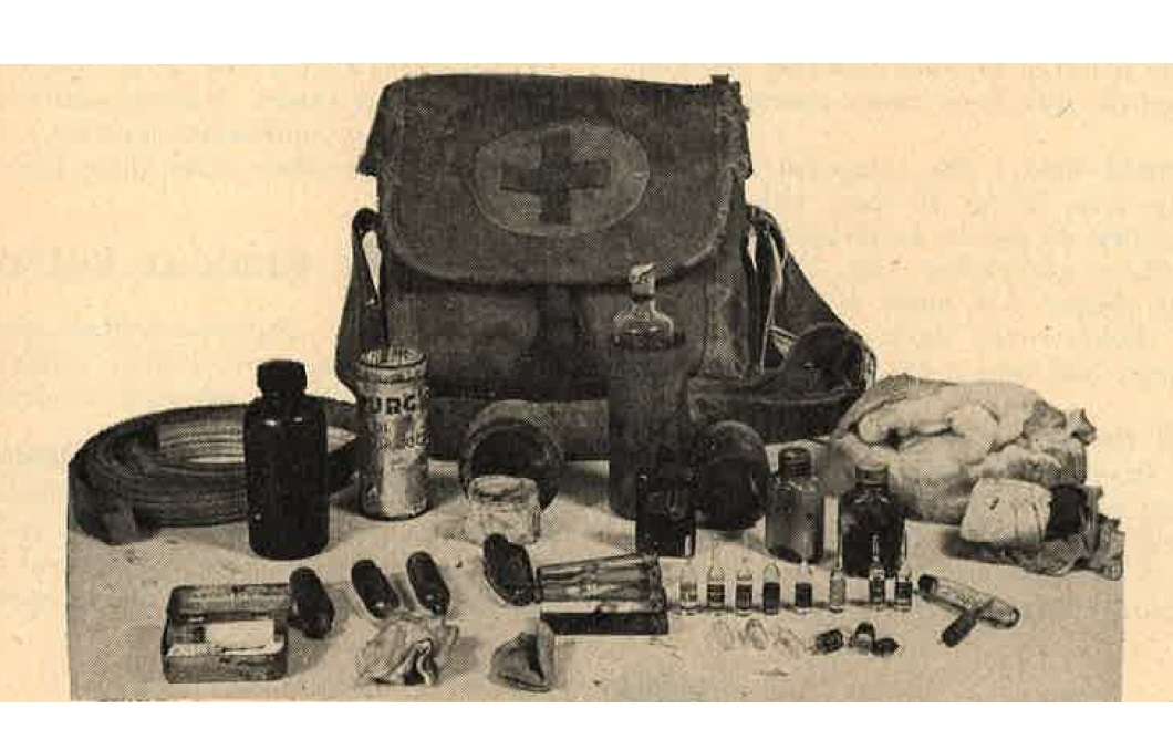
Figure 407. First aid kit and contents. |
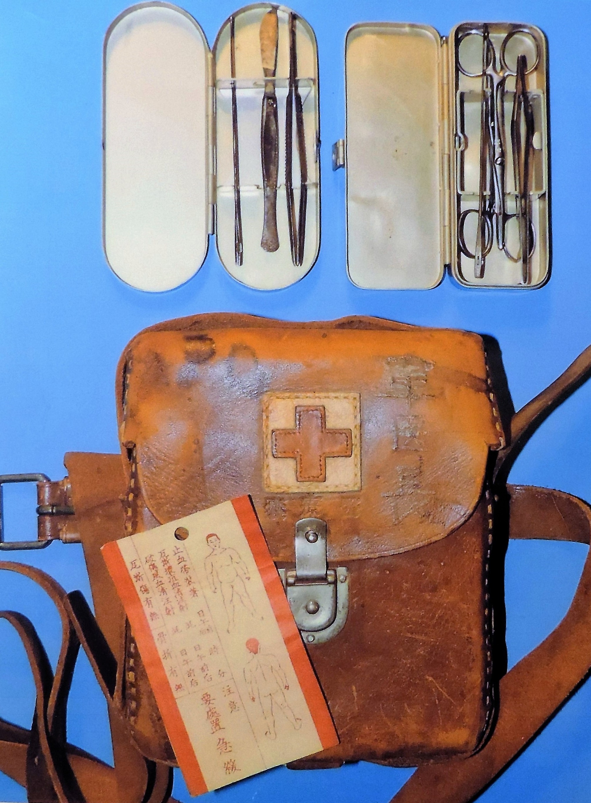
Figure 500. WWII Japanese field medical kit with contents. |
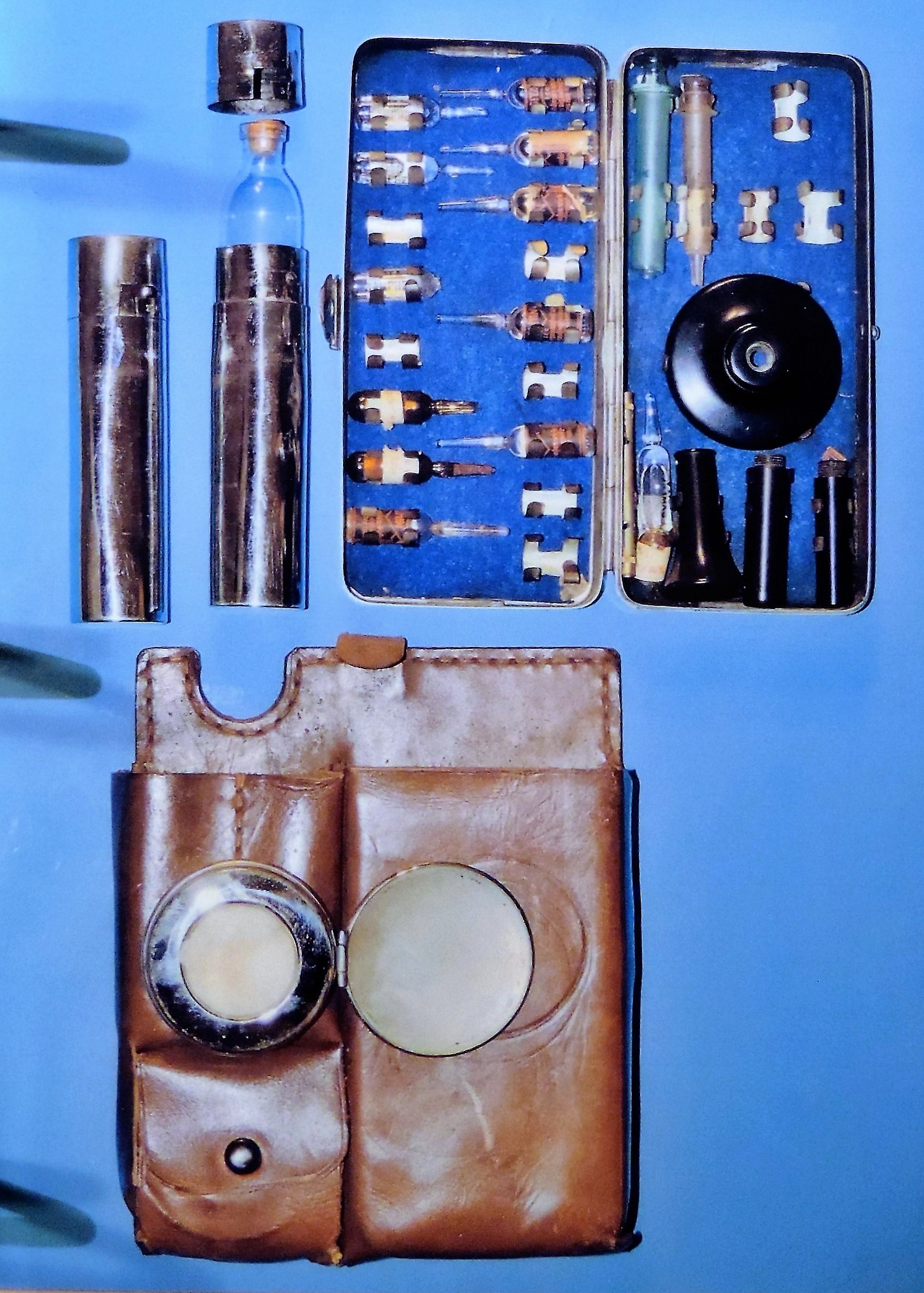
Figure 501. WWII Japanese syringe kit. |
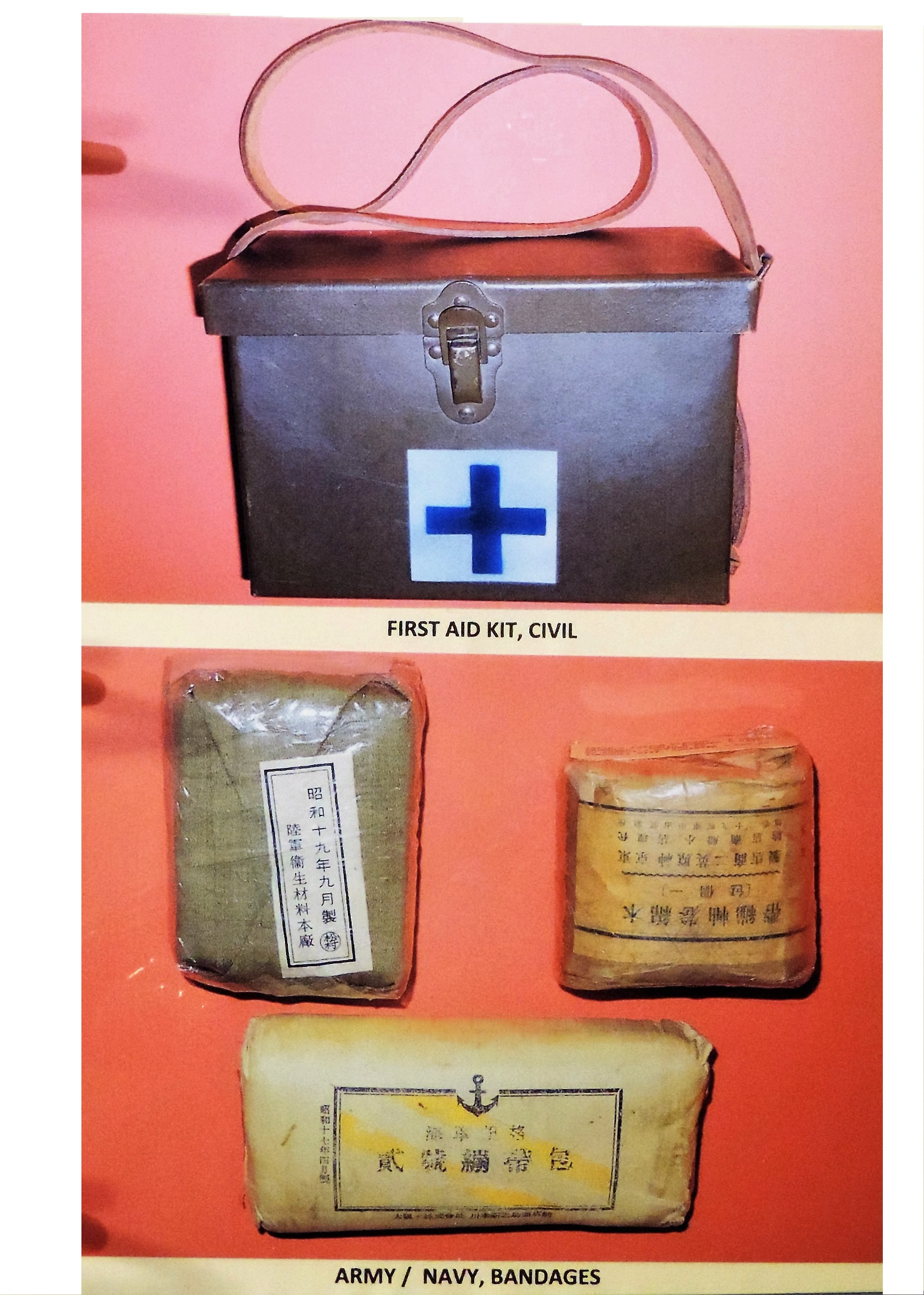
Figure 502. WWII Japanese civilian leather medical kit and miscellaneous army/navy bandages. |
| | ||
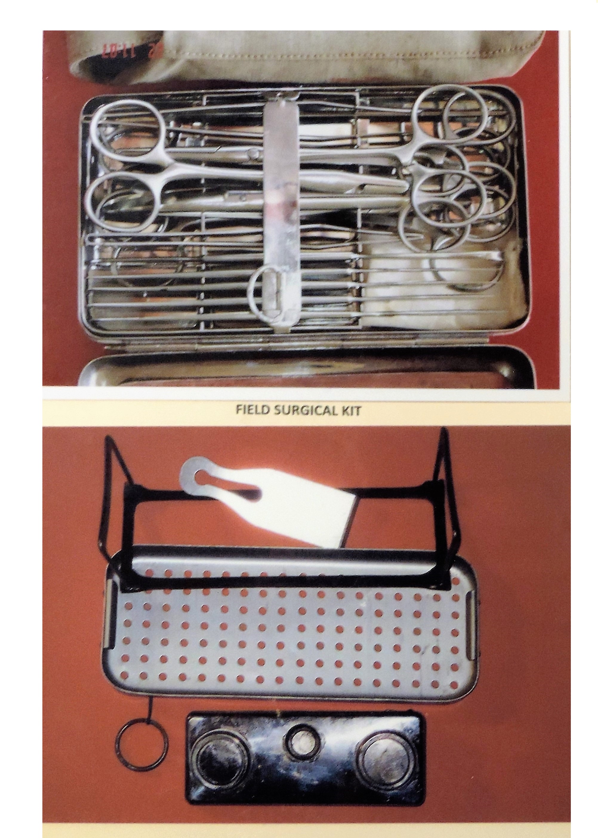
Figure 503. WWII Japanese surgical kit. |
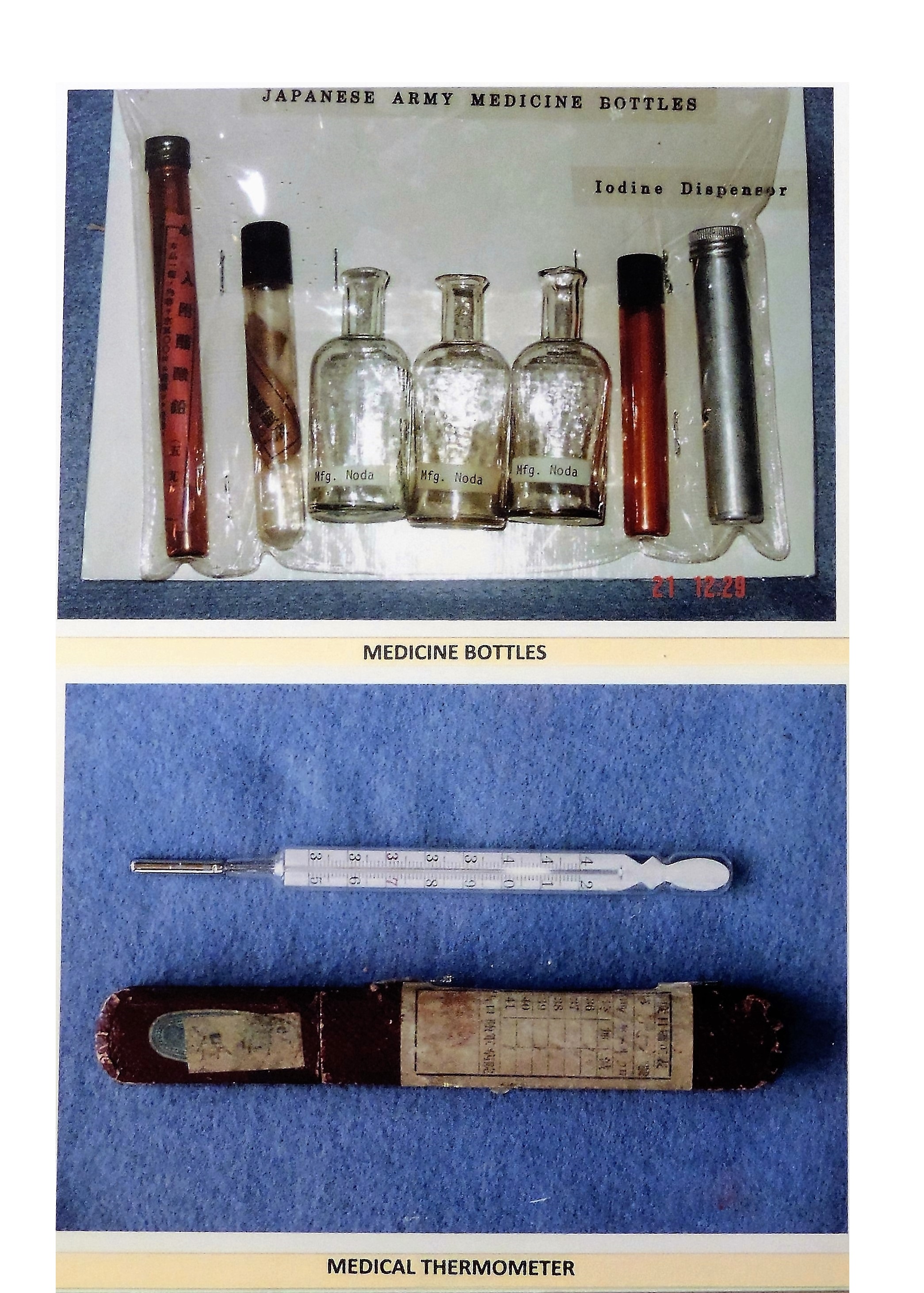
Figure 504. WWII Japanese thermometer and miscellaneous medical bottles. |
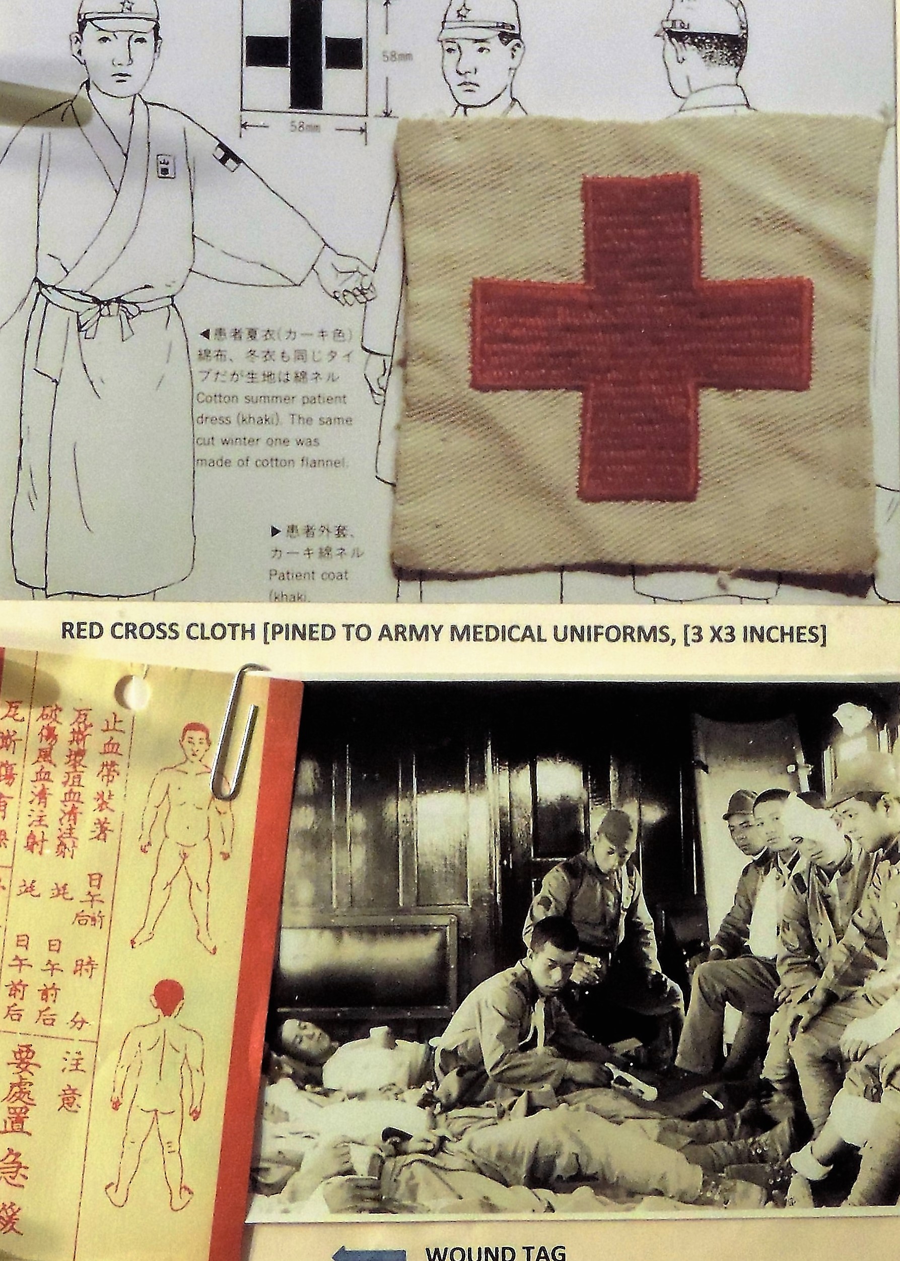
Figure 505. WWII Japanese paper wound tag. |
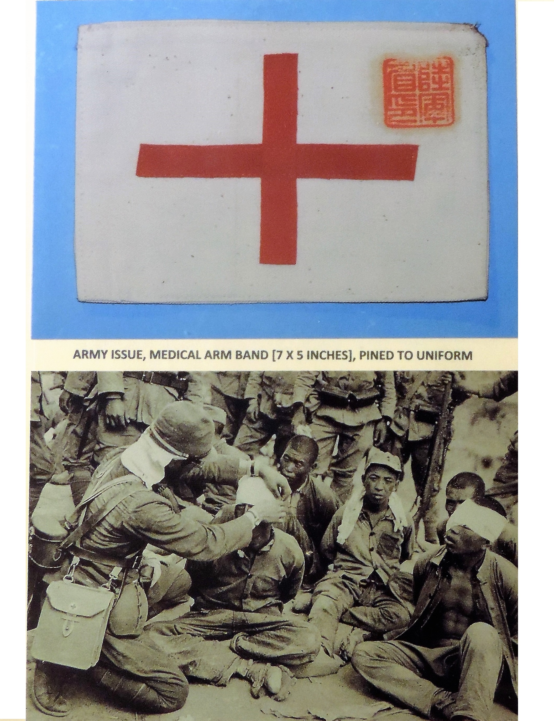
Figure 506. WWII Japanese medical armband. |
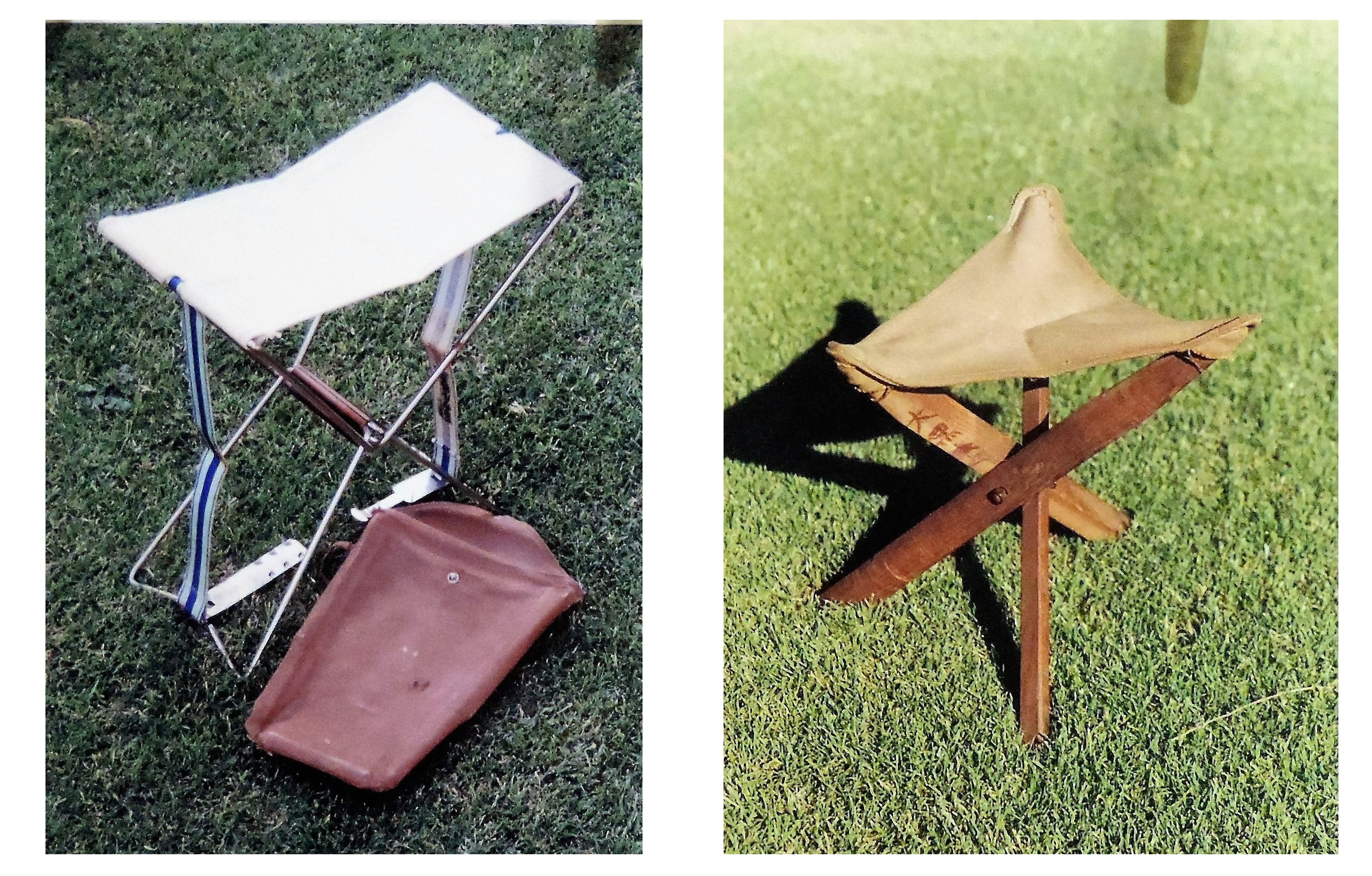
Figure 507. WWII Japanese Field medical stools. |