CHAPTER 9-D2 EQUIPMENT

SECTION V - WWII JAPANESE MILITARY ENGINEER EQUIPMENT.
1. GENERAL.
a. Japanese engineers are well equipped and are armed as infantry. They have shown outstanding ability in both the construction and demolition of bridges. On the other hand, airfields and roads so far encountered have not been up to Allied standards in speed of construction or serviceability. This may be attributed to the fact tha tthe Japanese have depended more on manual labor than on heavy equipment, which they have not taken into forward areas in any quantity.
b. The construction of field fortifications has been very highly developed, and even at remote points Japanese engineers have been successful in constructing first class defense positions from material immediately available. (for detailed description of various kinds of Japanese defensive constructions, see part 2, sections III and IV, chapter 7).
c. Engineers are also well equipped with a wide variety of explosive charges and other material for assault and demolition tasks,
d. The shipping engineers ( Sempaku Kohei ) are specially trained and equipped to operate a large variety of transport craft, including landing barges. (For a chart showing specifications of all known types of Japanese landing craft, see Chapter 8, fihure 157).
e. Pictures and detailed descriptions of certain items of engineer equipment will be found on the following pages.
2. WWII JAPANESE AMPHIBIUOS EQUIPMENT.
a. Bridges.
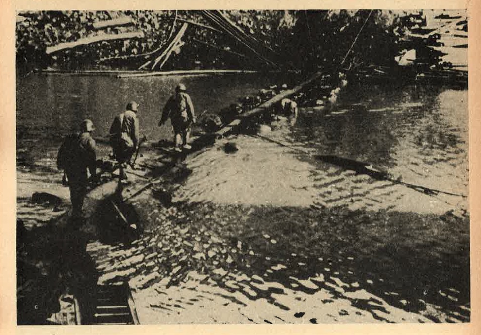
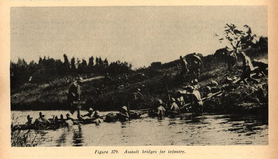
(1) Assault bridges. Several different models have been developed and standardized. Two types are illustrated in figures 379 and 380. one type is made of lengths of steel tubing, supported by bags filled with Kapok. The sections are joined together and afterwards locked. They are light enough to be carried by foot soldiers. Crossing of streams 100 feet and more in width are reported possible with this type of bridge.
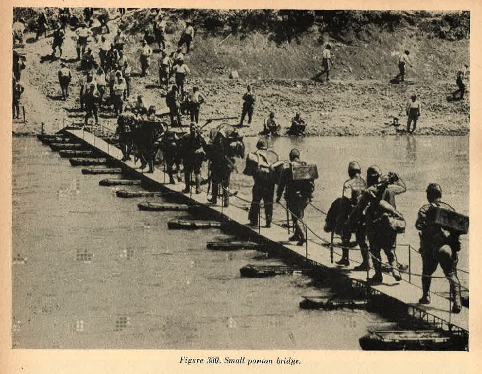
The foot bridge illustrated in figure 380 is supported by floats, each of which can be carried by one foot soldier. This type is for infantry only.
(2) Pontoon bridges. The heavier bridge is suitable for artillery and heavy equipment. The boats which support it are of standard sizes, especially developed for this work. One type, designed for transport by wagon, has 2 bow sections, each 8.7 feet long, and 2 center sections, each 7.1 feet long.
This boat weighs 1,650 pounds complete. An even larger boat of this type, which also comes in 4 sections, is 45 feet long and weighs 6,800 pounds complete. Another type is designed for packing by horses; it has 2 bow sections, each 4.4 feet long , and 3 center sections, each 4 feet long.
The complete boat weighs 921 pounds, and is slightly over 20 feet in length. An even lighter version also exists.
(3) Improvised trestle brisges. The Japanese are skilled in the constructionof wooden trestle bridges (Figure 381) which they erect with greatrapidity from materials prepared beforehand or available locally.
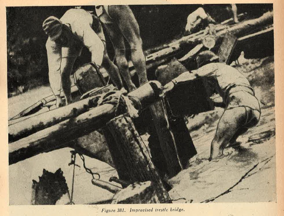
Joints usually are lashed with straw rope, and occassionally are strengthened with iron pins. Such trestles are found serving as approaches to ponton bridges in wide river beds; in shallow rivers they may be several hundred feet in length. Despite their flimsy appearance they are capable of supporting artillery and other heavy equipment.
(4) Sectionalized steel bridges. Prefabricated steel bridges are used by the Japanese, but not as widely as by some other armnies. One truss-construction, portable, steel bridge si 48 feet long and weighs 820 pounds.
b. WWII Japanese Assault boats.
(1) Collapsible boats. Several types of collapsible boats have been developed. One of these, Model F (Figure 382) is am outstanding example of assault boat design, and is very widely utilized.
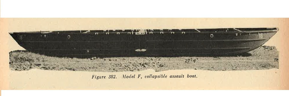
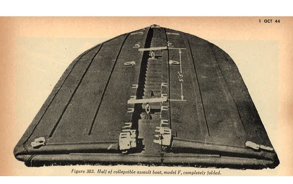
The boat, divided into two sections, each of which collapses flat on itself, (Figure 383) is individually floatable. Each section is 13.6 feet long, 4.75 feet wide, and 2.18 feet high. The wooden frame is braced, and all joints are bonded with rubber. The boat will hold 20 men, and it is estimated that 9 such boats could be loaded flat on a 2 ton truck.
 |
Light outboard motors have been used to propel this boat. Three types of rubber (pneumatic) boats, of from 1 to 10 man capacity, are in use. These are similar in construction to the rubber boats used by other armies. |
(2) Demountable boats. Japanese engineers also operate a variety of demountable motor boats, fitted with outboard and inboard motors of various kinds. One small 30-foot boat breaks into 4 sections and is propelled by an outboard motor. some of the outboard motors are arranged for animal pack. Another larger type breaks into only 2 sections; the stern section is filled with a 4-cylinder, inboard gasoline engine of 30 horsepower. It is not believed that any of these demountable boats permanently mount any weapons.
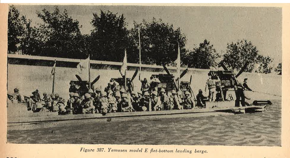
c. Landing barges.
(1) Japanese engineers operate a large variety of landing barges, which have been employed extensively in various theaters. Since Allied air superiority has seriously interfered with Japanese use of transports in many theaters, landing barges generally have been employed foe the supply and evacuation of their forward areas. As many as 500 of these craft have been found congregated in one port.
(2) Some of the design features of these small vessles are of interest. The landing barge screw shown in Figure 384 is designated for operation in shallow waters and affords maximum protection to the screw.
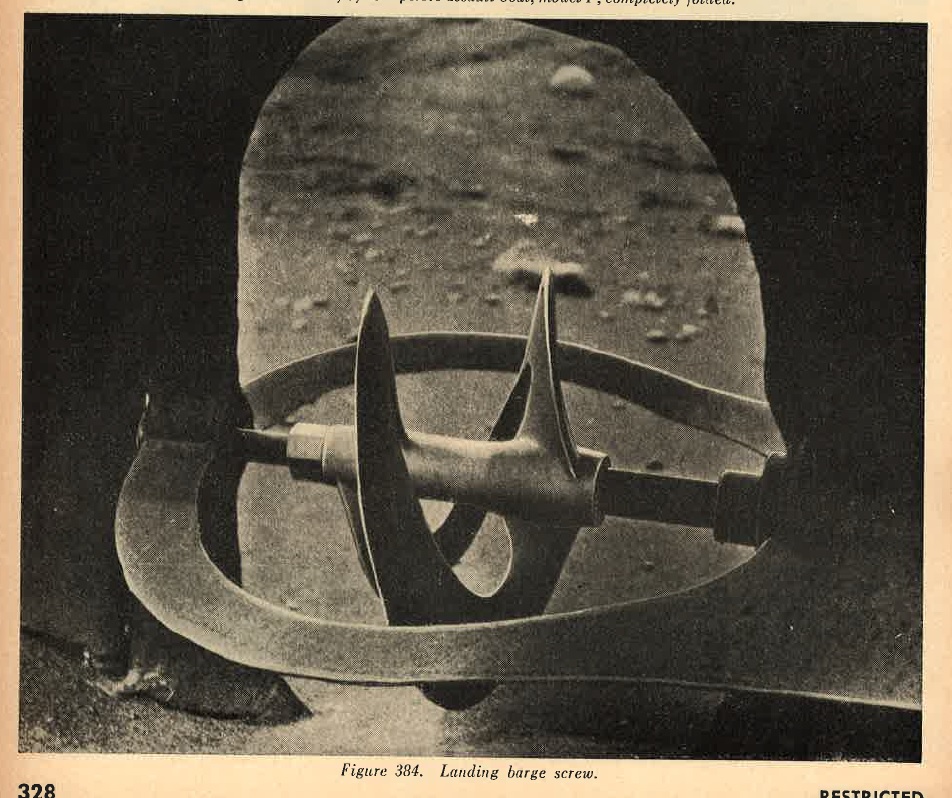
The Japanese generally are credited with the development of he folding ramp, which now is used so extensively.
(3) A typical landing barge is the Daihatsu Model A (Army). The Daihatsu is probably in wider use than any other type; the picture is Figure 385 gives a general ideal of it.
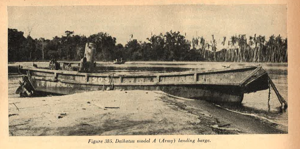
(4) The specifications of teh Daihatsu illustrated in Figure 385 are as follows:
| 1. | Length | --------- | Approximately 49 geet. |
| 2. | Beam | --------- | 11 to 12 feet. |
| 3. | Height | --------- | Approximately 6.5 feet. |
| 4. | Draft | --------- | 3 to 4 feet. |
| 5. | Freeboard | --------- | 1.5 to 2 feet amidships. |
| 6. | Speed | --------- | 6 knots (cruising (10 knots maximum) empty). |
| 7. | Engine | --------- | Diesel, 6 cylinder, 60 to 80 horsepoer, preferred. Some may have heavy oil, electric ignition, or gasoline engines. |
| 8. | Capacity | --------- |
100 to 120 men (short hauls only) 40 to 50 emn on longer trips, or 10 to 15 tons, or 1 light tank (7 to 9 tons), or 1 150-mm howitzer (6 to 7 tons, complete). |
| 9. | Crew | --------- | 5 to 7 men. |
| 10. | Armament | --------- | Not standardized. However, at least two machine guns, or one or two 13-mm heavy machine guns. Fire from 20-mm guns has been encountered from this type, and on several occassions 37-mm guns have been found. |
| 11. | Armor | --------- | A vertical shield of steel, .12 to .36 inch thick, usually protects the coxswain and control gear from frontal fire. Occassionally this type has steel plates, 15 inches by 12 inches, .36 inch thick, hooked to gunwales. |
| 12. | Construction | --------- | Based on standard Japanese fishing boat design, this landing barge has been developed over a long period of years. The metal hull, about .2 inch thick, is of welded steel plate, supported by heavy wooden braces. The twin keels at the bow are of heavier steel and are riveted. The bow ramp is of wood, and teh sides above the waterline are covered with timber. The Daihatsu has an open cockpit in the middle, with a watertight compartment at each end. The engine room at the rear is steel decked. |
This clumsy looking vessel is surprisingly versatile, and will stand a great deal of abuse. Its heavy double keeled bow and protected screw make it very serviceable in shoaly, rock infested waters.
a. Rollers. Various types of road rollers, of small, medium, and large sizes, have been encountered. All are of simple and sturdy design. The small roller shown in Figure 388 weighs about 9 tons and is powered with a Ford Model B, 4-cylinder, gasoline engine. The medium roller shown in Figure 389, about 18 tons in weight, is Diesel powered. Largerrollers also have been captured.
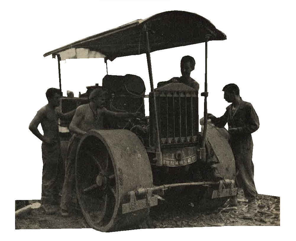
Figure 388. Small gasoline roller.
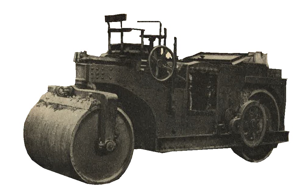
Figure 389. Medium Diesel powered roller.
b. WWII Japanese military Prime movers. For detailed specifications, see Section III of this chapter.
c. WWII Japanese military Power rock crushers. Power rock crushers of rather small capacity, but of good condtruction, have been seen. Power is furnished by small Diesel motors. These rock crushers are found mounted in pairs, usually on a platform.
d. WWII Japanese military Concrete mixers. Portable concrete mixers (Figure 390) of various types have been developed by Japanese engineers. The mixers, some of which are Diesel powered, can be moved easily from one job to another and erected on a platform to facilitate pouring. Some army types are mounted permanently on trucks.

Figure 390. Diesel powered concrete mixer.
e. WWII Japanese military Portable railroads. Japanese engineers make extensive use of portable railroads of various kids. One standardize type has been gauge of two feet. Rails are small in section, weighing about 10 pounds per foot. and are 18 feet in length. They usually are laid for temporary use. Switch sections are prefabricated. Light flatcars, 4 feet wide and 6 feet long are used on this type of portable railroad.
Racks or sideboards can be fitted to give increased capacity to the flatcars. Such light cars can be pushed by manpower, or pulled by small, gasoline powered locomotives.
f. WWII Japanese Mobile power driven saw. The power saw is another piece of Japanese construction equipment used in forward areas, where defenses must be constructed in forward areas, where defenses must be constructed of heavy logs. Power is furnished by a small gasoline motor. In rear areas, larger circular saws, permanently installed and driven by belt from Diesel motors, will be found.
g. WWII Japanese Mobile well driller. The heavy, mobile, power operated well driller is used in favorable terreain. Power is furnished by the truck engine, which drives an air compressor connected with a large compressed air tank.
h. WWII Japanese Miscellaneous construction equipment. A wide variety of miscellaneous equipment for construction of bridges, defense works, roads and airfields has been developed by Japanese engineers. In the forward areas so far overrun, however, main reliance has been placed on labor troops rather than on mobile equipment. Moreover, it is felt that Japanese engineers have not developed prime movers and earth-moving equipment of the heaviest variety. Although medium weight equipment of these categories has been identified.
a. WWII Japanese Electric power units. Electric generating units, both mobile and heavy, usually Diesel powered, are in wide use. They usually are of standard design and are utilized to supply light and power for a variety of purposes. On one island fortress, Diesel powered generator units ranged from 20 to 100 KVA, all 2,300 volts, 3-pahase, 50 cycle. Underground cables led to intermediate transformer vaults, where the current was stepped down to 110/220 volts for consumption by gun turret motors and communications equipment.
Searhlights were DC arc type, with motor generator converters. A large number of battery charging panels served to charge batteries for communication equipment.
b. WWII Japanese Ice plants. Ice plants of varying capacities have been found on several islands occupied by the Japanese. These are well constructed (Figure 391), and some of them have been used by our troops for long periods.
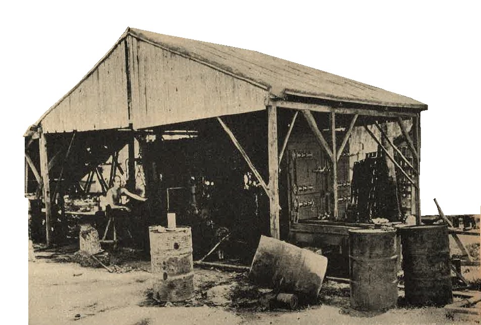
Figure 391. Field ice plant.
Japanese demolition equipment is similar to that of other armies, but unusual attention has been given to small demolition charges employed in assault tasks. Much use is made of picric acid, and serious efforts have been made to preserve this compound from moisture. Plastic explosives also have been used by the Japanese for some time. ALthough electric detonators have been well developed, the Japanese take a very practical view of equipment of this nature, and therefore have retained friction-type igniters in many instances because of their simplicity.
a. WWII Japanese Small demolition charges. In addition to those described in section I, Chapter 9, a variety of small charges, in either block or cylindrical form, are available. Picric acid, TNT, and toluol cheddite (Ammonium perchlorate 76 percent) are used in these charges, some typical specifications of which are as follows:
(1) Block charges.
| 1. | Length | --------- | 2.8 inches. |
| 2. | Width | --------- | 1.6 inches. |
| 3. | Thickness | --------- | 2 inches. |
| 4. | Weight | --------- |
Picric acid and TNT .44 pound. Toluol cheddite .42 pound. |
(2) WWII Japanese Army Cylindrical Demolition charges.
| 1. | Length | --------- | 4.6 inches. |
| 2. | Diameter | --------- | 1.2 inches. |
| 3. | Weight | --------- |
Picric acid and TNT .22 pound. Toluol cheddite .20 pound. |
There are several containers for these small charges. One Zinc can, wired for an electric detonator, has the following specifications:
| 1. | Length. | --------- | 8.2 inches. |
| 2. | Width. | --------- | 2,2 inches. |
| 3. | Thickness. | --------- | 3 inches. |
This can contains three of the block charges mentioned in (1) above and is very widely used.
b. WWII Japanese Army Large Demolition charges. In addition to the bangalore torpedo described in Section IV, much larger demolition charges in this form are unsed by engineers. One large bangalore torpedo consists of 4 sections and a large detonator. Each section contains 10 of the cylindrial charges described in a (2) above. The assembled torpedo is 34 feet long and weighs 225 pounds. Other large charges are assenbled in various forms as needed, with the addition of plastic explosive when necessary.
c. WWII Japanese Plastic explosive. This explosive has the following composition:
| 1. | Cyclkonite | --------- | 80 percent. |
| 2. | Vegetable oil binder | --------- | 20 percent. |
It is issued in rolls, 4 inches by 1.12 inches, each roll weighing .25 pound. These rolls are individually wrapped in parchment and in turn wrapped in a paper package.
d. WWII Japanese military Detonators.
(1) Nonelectric detonators. Several types have been recovered. One very large, non-electric detonator has the following specifications:
| 1. | Length | --------- | 2.7 inches. |
| 2. | Diameter | --------- | 0.3 inch. |
| 3. | Contents | --------- |
Fulminate of mercury - 88 grams PETN - 4 grams. |
This detonator is made of brass.
(2) Electric detonators. There are a number of types and sizes. Model 97 (1937) electric detonator has outer and inner cases, both of brass, and has the following specifications:
| 1. | Length | --------- | 3.25 inches. |
| 2. | Diameter | --------- | 0.27 inch. |
| 3. | Contents | --------- |
Fulminate of mercury ...... 3.93 grams Fulminate of mercury plus a deadening agent ..... 0.28 grams PETN ..... 1.98 grams. |
(3) WWII Japanese Pull igniters.
(4) Several types of slow burning and instantaneous fuzes have been developed. The instantaneous type (Primacord) is protected by a rubber impregnated, hemp thread cover.
Japanese transits, theodolites, map scribers, and reproducers are of good quality and workmanship. In design and development the Japanese have closely followed or even duplicated European or American patterns, and calibraions and markings usually are in Arabic numerals. Allied engineers have no difficulty in making good use of these instruments in the field.
SECTION VI - WWII JAPANESE CAVALRY AND RECONNAISSANCE.
1. GENERAL.
The Japanese have given much thought to the cavalry arm, which is particularly useful in Manchuria and North China. Their specially bred cavalry horses, the get of Anglo-Arabian sires and native mares, average about 14.3 hands (approximately 57 inches). They have proved satisfactory, since they are sturdy, enduing, and relatively speedy.
2. WWII JAPANESE HORSE SADDLES.
| The saddle (weight about 46 pounds with saddle bags, etc.) shows evidence of both English and American design (Figure 392). |
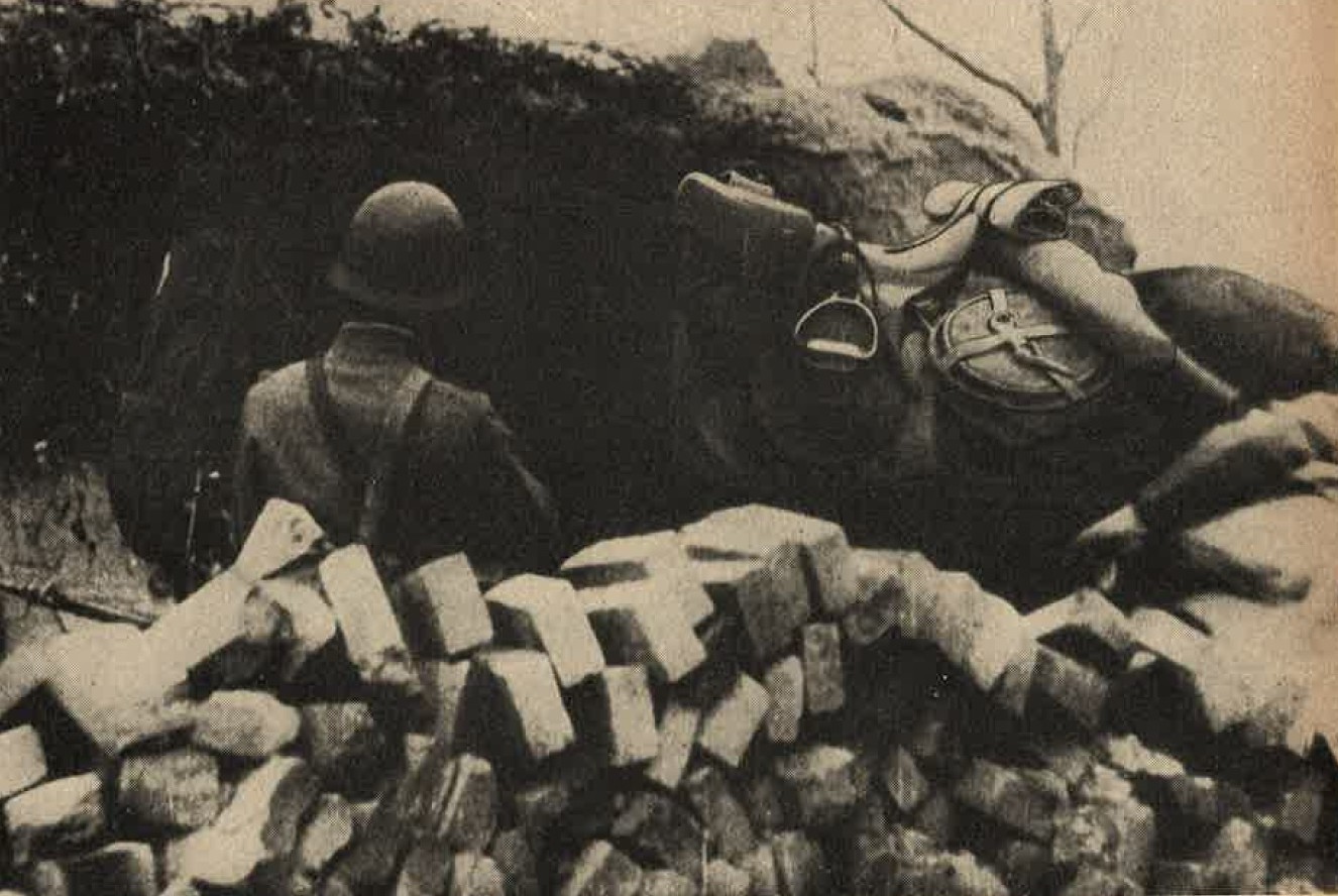
Figure 392. Standard cavalry saddle. |
3. WWII JAPANESE CAVALRY SABER.
|
The saber is a combination of a European type hilt with a Japanese cutting blade. It is 40 inches in length and weighs
3.13. pounds (Figure 393).
The handle is made of wood and has a checkered pattern. A "D" shaped hand guard is present. The scabbatd is painted green and has a drag at the tip. A locking mechanism secures the blade in place. A Brown leather set of straps are attached to the scabbard. They hold the sword in place to the uniform. |
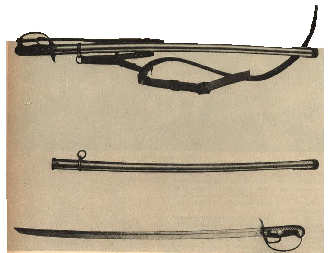
Figure 393. Standard cavalry saber. |
4. WWII JAPANESE MILITARY OTHER EQUIPMENT.
a. The individual trooper carries Model 44 (1911) 6.5-mm cavalry carbine (See section II, Chapter 9). The horse artillery of the cavalry brigade is armed with a 75-mm field gun, which is a variation of the Model 38. It is possible that Model 95 (1935) 75-mm field gun also is used by these units. Light and heavy machine guns are standard equipment of cavalry brigades.
b. The Japanese have formed reconnaissance units which contain both mounted troops and motorized units. In these latter units, tankettes, and possibly armored cars (See section IV, Chapter 9), will be found. Personnel of such units are armed like the horse troops, except that the saber may be omitted.