CHAPTER 9 - WWII JAPANESE ARTILLERY AND CHEMICAL

SECTION III - WWII JAPANESE ARTILLERY
1.GENERAL
Between 1925 adn 1936, all Japanese artillery pieces were either redesigned or replaced by newer designs. An examination of a majority of the designs known to exist leads to the belief that the following features will be incorporated in any newer designs produced since 1936, although no weapon over 47-mm in size and bearing a model date later than 1936 as yet have been reported:
- Hydropneumatic recoil system.
- Use of equilibrators.
- Muzzle breaks.
- Increased muzzle velocities.
- Improved high speed mounts on all medium and heavy pieces (using either pneumatic tires or tires filled with sponge rubber).
Since Japan has had access to German weapon design for some years, it may be assumed that the Japanese weapons embodying the following features may be encountered:
- Hollow charge projectiles.
- New incendiuary projectiles.
- Self propelled mounts of various kinds.
- Rockets.
2. FIELD ARTILLERY.
a. Model 94 (1934) 75-mm mountain (pack) gun.
(1) General description. This is the standard Japanese pack artillery piece (figure 216) which replaced the Model 41 mountain gun. Designed for rapid assembling and dismantling, it breaks down into 11 units, the heaviest of which weighs 210 pounds. The weapon is normally transported by 6 pack horses. It is characterized by a comparatively long split-trail hydropneumatic recoil mechanism, and a horizontal sliding breechblock. The shield is 1/8-inch armor plate.
(2) Characteristics.
(3) Ammunition. HE, AP, sharpnel, chemical, star, and incendiary. |
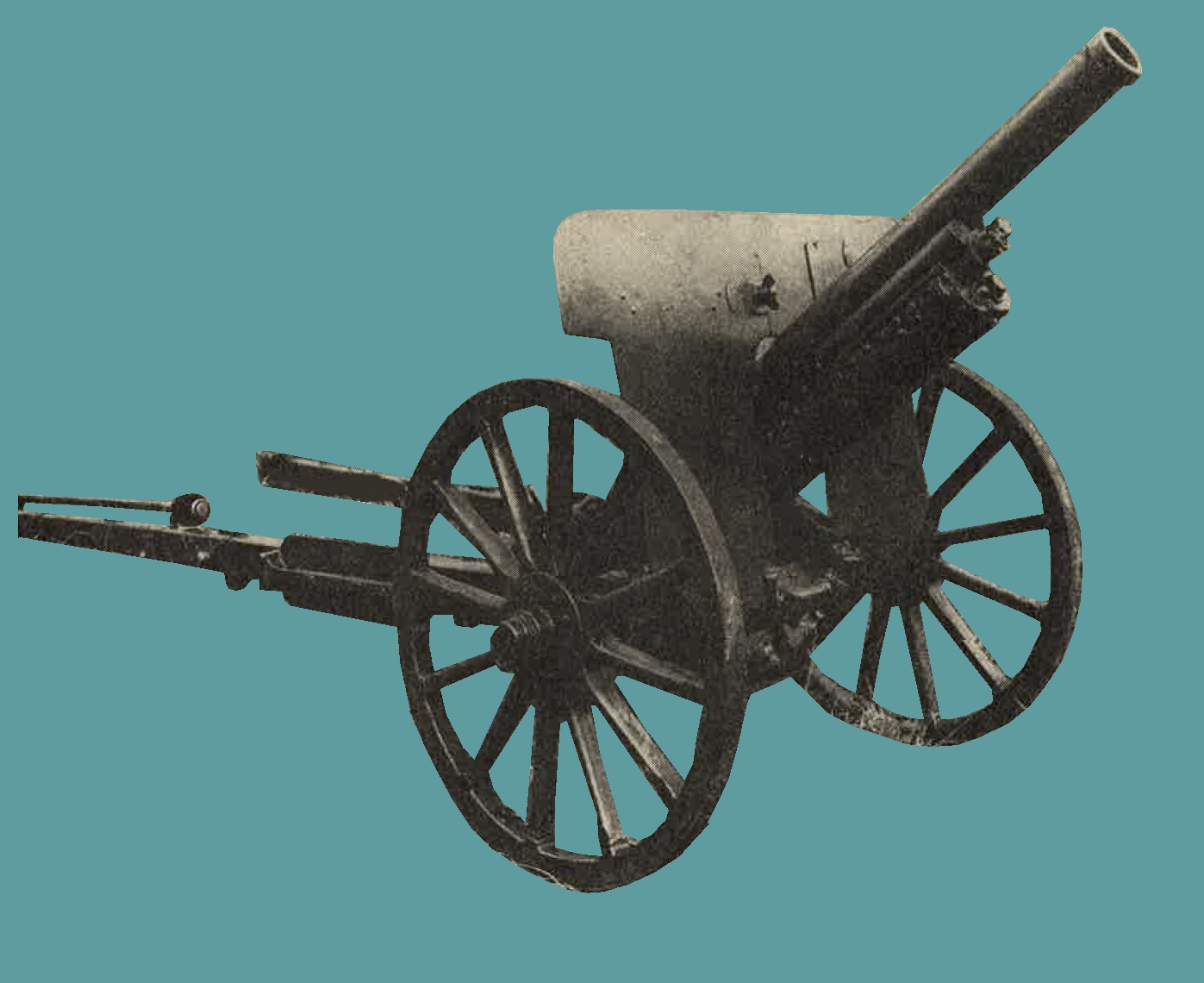
Figure 216. Model 94 (1934) mountain (pack) gun. |
b. Model 38 (1905) 75-mm gun.
General description.
(1) One of the early weapons of the Japanese division artillery, this weapon (figure 217) has been subject to considerable modification, and several versions are known to exist. There is no evidence that this parent model has been employed in recent operation; probably now it is regarded as obsolete (1944). It may be readuly identified by the single box trail which, by its design, considerably limits the elevation of the piece. Other characteristics are a hydrospring recoil system, interrupted screw type breechlock, and 1/16-inch shield.
2. Characteristics.
(3) Ammunition. HE and AP. |
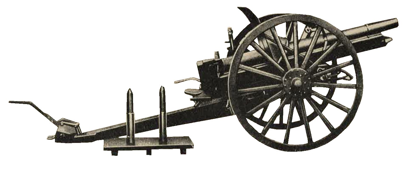
Figure 217. WWII Japanese 75-mm gun with ammunition. |
c. Model 38 (1905) gun improved (possibly 4th year model).
(1) General description. This is an improved version of the 75-mm model 38 (1905) field gun, which appears to have been entirely replaced. Modifications on the present model (figure 218) consists of trunnioning the barrel further to the rear; the addition of two spring and cable equilibrators to compensate for muzzle overhang; Replacement of the old box trail by a longer open box type through which the barrel can recoil at high elevations; change the breech to a horizontal sliding wedge mechanism, the most significant results of the above modification are a much longer range and increase rate of fire. Although reports have indicated that this weapon was to be replaced by the Model 90, the fact that the newer gun has not been encountered in any combat areas (as of 1944) indicates that this plan has not yet beeb consummated.
(3) Ammunition. HE, AP, sharpnel, smoke, star shell, and chemichal. |
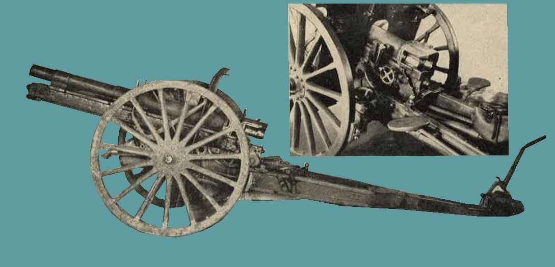
Figure 218. Japanese Model 38 (1905) gun improved (Insert shows breech mechanism). |
d. Model 90 (1930) 75-mm gun.
(1) Geenral description. Surrounded with considerable secrecy by the Japanese, this gun (figure 219) has been reported as the modern weapon of the division artillery. In 1936 it was believed to have been in process of issue to organizations, but to date (1944), it has not been encountered in any theater of war.
The gun is equipped with either pneumatic tires for motorized towing or large , steel-rimmed wheels for horse draft. It is characterized by a split trail, a horizontal sliding breechlock, and a hydropneumatic recoil system. An ususual feature is the muzzle break, which as of 1944, it had not been found on any other artillery piece.
(3) Ammunition. HE, AP, sharpnel, incendiary, smoke, star shell. |
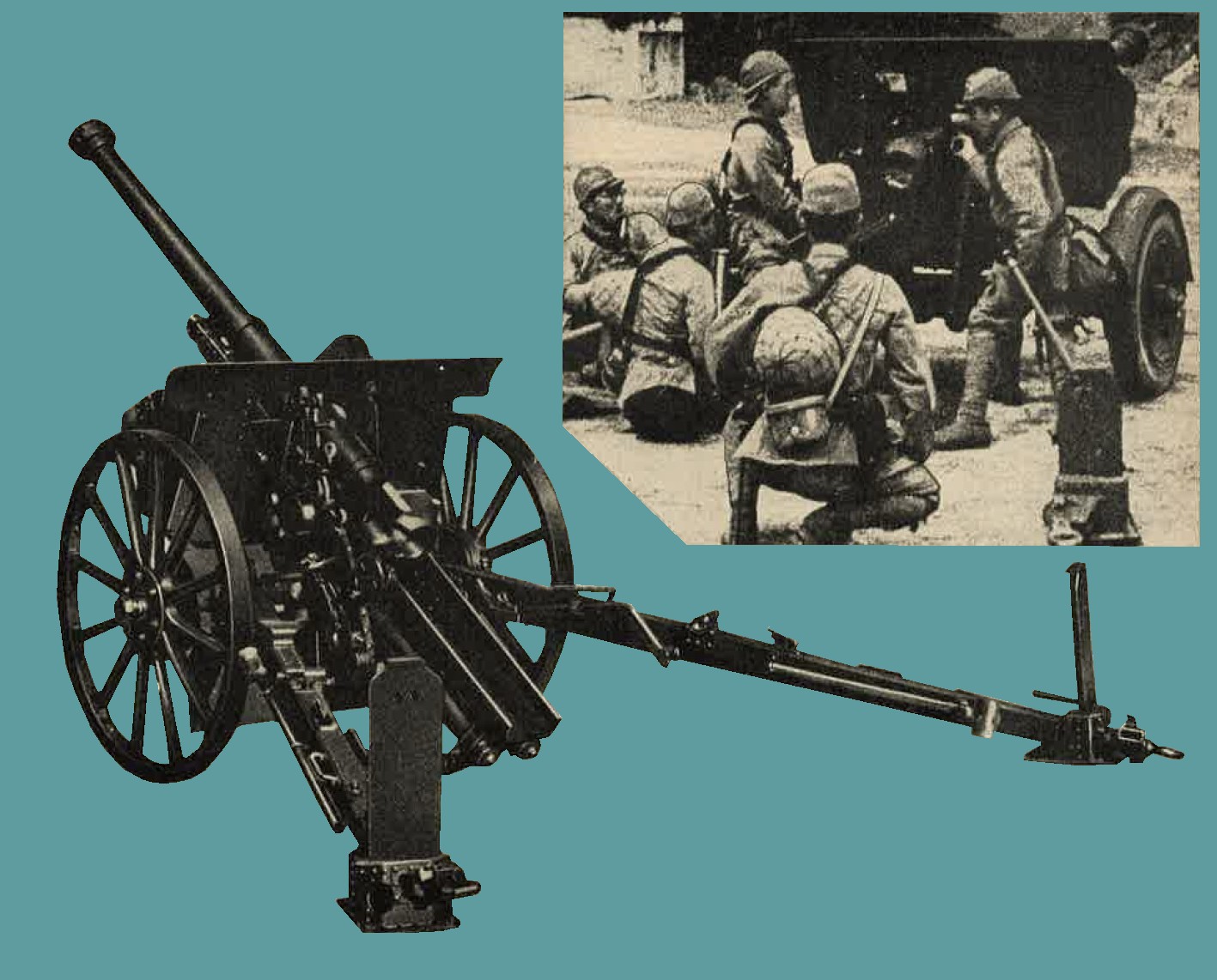
Figure 219. WWII Japanese Model 90 (1930) 75-mm gun (insert shows the weapon on a high speed carriage with pneumatic type tires). |
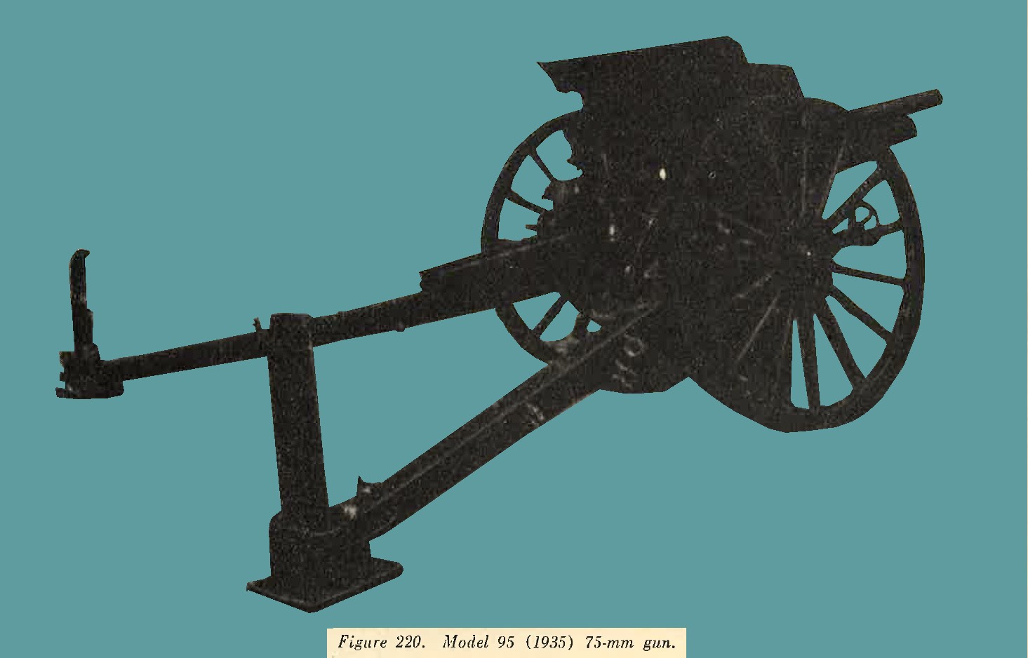
e. model 95 (1935) 75-mm gun.
(1) General description. The 75-mm Model 95 gun is a horse drawn (figure 220) with split trails, hydropneumatic recoil mechanism, and horizontal, sliding-wedge type breechlock. A comparison with the Model 90, designed 5 years earlier, reveals that this later weapon has only the apparent advantage of reduced weight. On the other hand, it suffers from loss of range and lower muzzle velocity. It is seemingly more rugged in construction than the Model 94 mountain gun and yet gives a lower performance than he Model 90 field gun.
The possibility therefore suggests itself that the Model 95 was not designed to replace other of these guns, but was to be used by some unit other than the field or pack artillery. It is possible therefore that it may be the new weapon of the horse artillery, replacing the old adaptation of the Model 38 with which such units previously had been equipped.
* Also reported as 9,000 meters (9,850 yards). (3) Ammunition. HE, AP, sharpnel, smoke star and chemical. |
 |
f. Model 14 (1925) 105-mm gun.
(1) General description. The 105-mm Model 14 (1925) gun (figure 221) is used for long range fire. There is no information, as of 1944, to show that this gun is still in production, and ir is felt that in all probability it has been superseded by the more modern Model 92 (1932).
This artillery piece was mounted on heavy wooden wheels, the weapon is normally tractor drawn, and is capable of being moved at a maximum speed of 8 miles per hour. As an alternative it may be drawn by 8 horses. The weapon possesses an interrupted screw breechlock, a hydropneumatic recoil mechanism, and a split trail.
(2) Characteristics.
|
 |
(3) Ammunition. Ammunition is semifixed. The following types of projectiles have been reported:
- High explosive (long pointed shell).
- High explosive.
- Sharpnel.
- Chemical.
- Armor piercing.
Time fuses are provided for the smoke, incendiary, and sharpnel projectiles. The standard Model 88 point detonating (instantaneous or delay) fuzes are used with HE and chemical shells.
g. Model 91 (1931) 105-mm Howitzer.
(1) Genral description. A light weight modern field piece (figure 222) possessing a hydropneumatic recoil mechanism, split trail, and interrupted screw breech mechanism. The weapon can be readily identified by the short barrel and long sleigh. Normally it is towed by six horses.
|
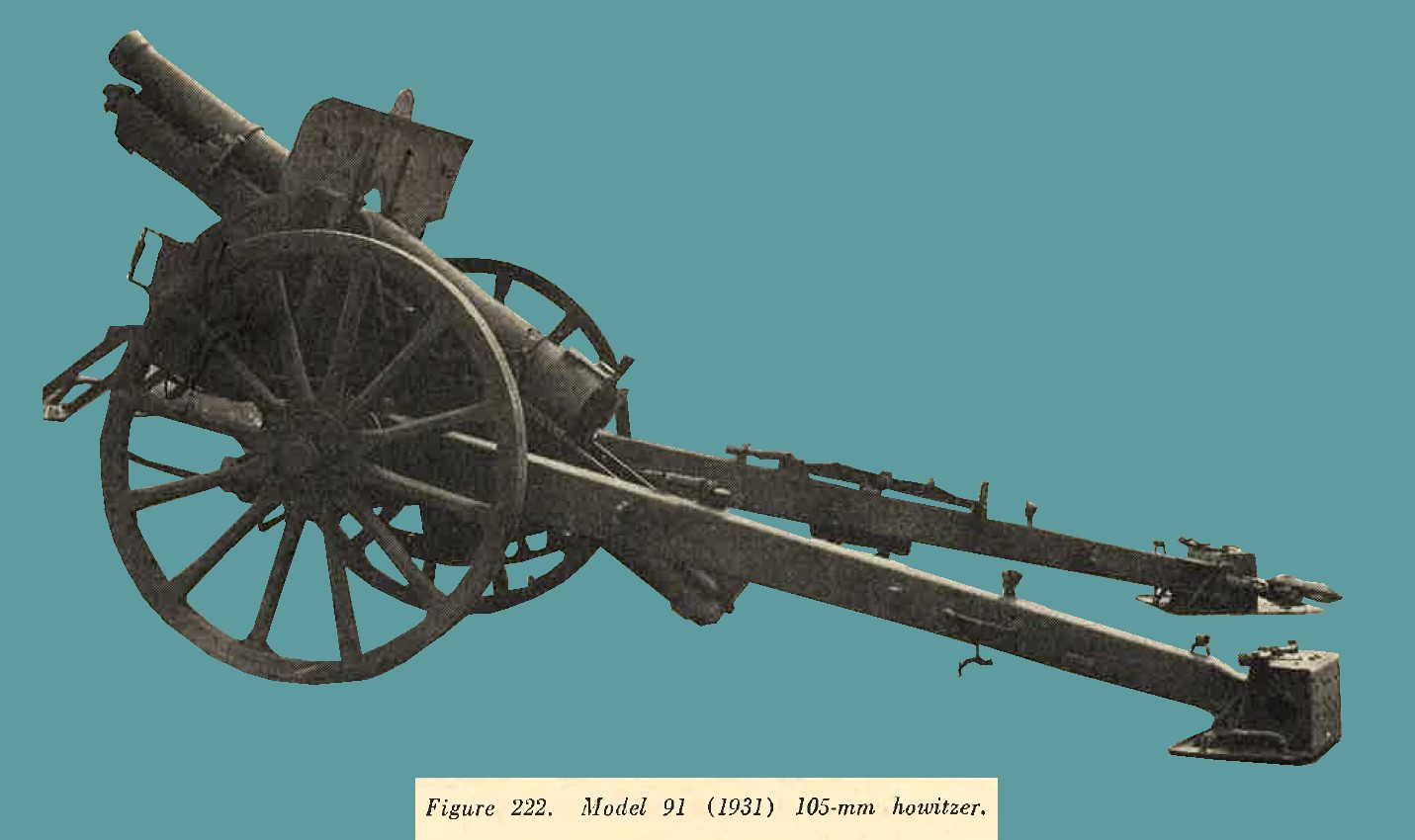 |
(3) Ammunition. Ammunition is semifixed. The following types of projectiles have been reported: - High explosive (long pointed shell).
- High explosive.
- Armor piercing.
- Sharpnel.
- Chemical.
h. Model 92 (1932) 105-mm gun.
(1) General description. It is considered that this weapon (figure 223) has superseded the Model 14 (1925) 105-mm gun. Readily recognized by its long slender barrel and trail, it has been designed [particularly for long range fire. Other distinctive features are the pronounced length of the sleigh and the three step interrupted thread breechlock. The recoil system is hydropneumatic. Mounted on heavily constructed wooden wheels with solid rubber tires, the weapon is normally tractor drawn, but may be drawn by a 5 ton truck.
|
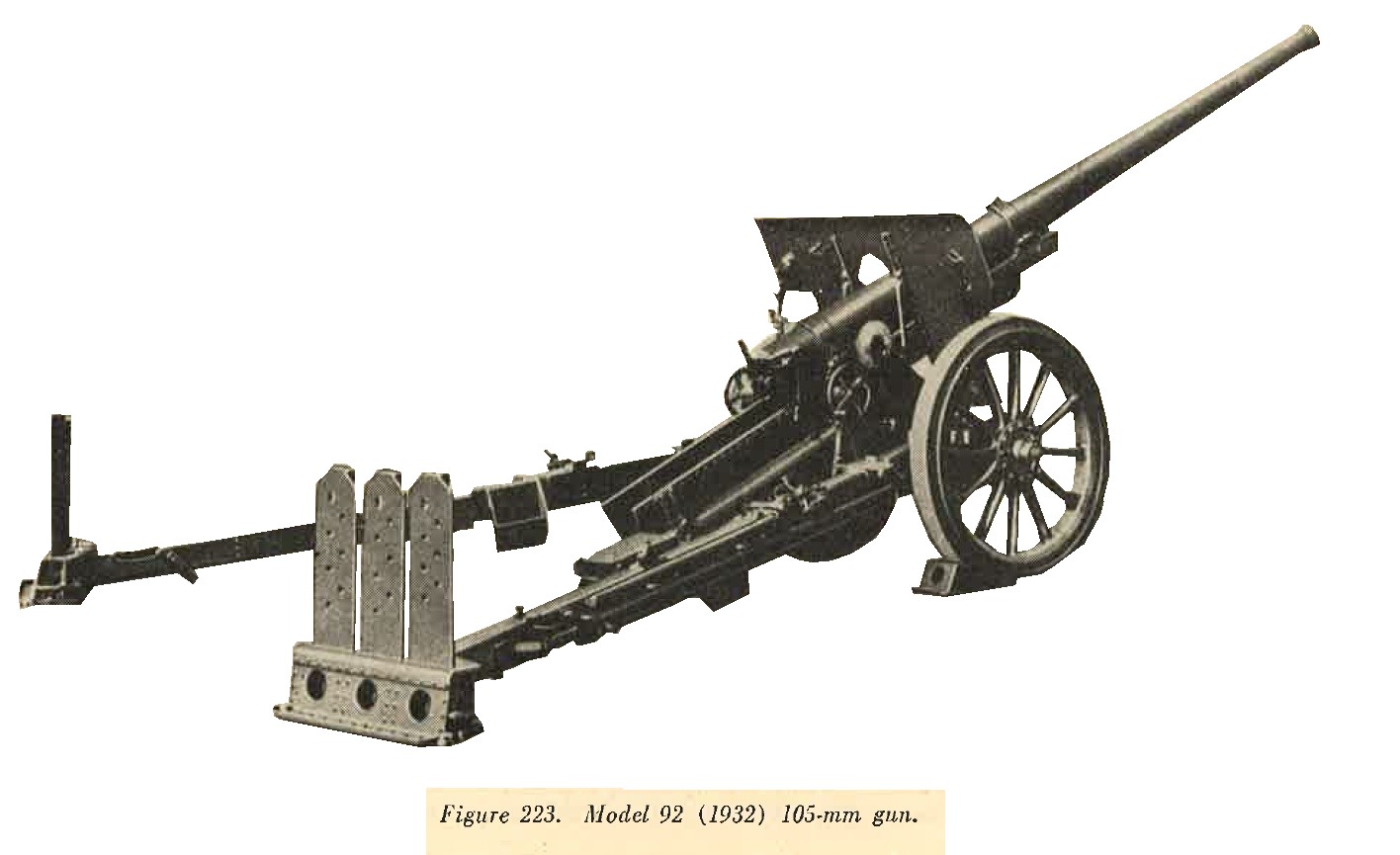 |
(3) Ammunition. Ammunition is semifixed. The following types of projectiles have been reported: - High explosive (long pointed shell).
- High explosive.
- Chemical.
- Armor piercing.
Time fuzes are provided for the smoke, incendiary, and chemical shells. The standard Model 88 point detonating (instantaneous or delay) fuzes are used with the HE and chemical shells.
i. Model 4 (1915) 150-mm howitzer.
(1) General description. One of the older type horse drawn weapons (figure 224) which nevertheless is still in service. For purposes of transportation the trail breaks in the middle. The barrel is removed from the cradle and placed on the rear portion of the trail, to which has been attached an extra pair of wheels. a limber is attached to each section, and each load may then be towed by six horses. The weapon possesses a vertical sliding breechlock, a hydropneumatic recoil mechanism, and a box type trail.
|
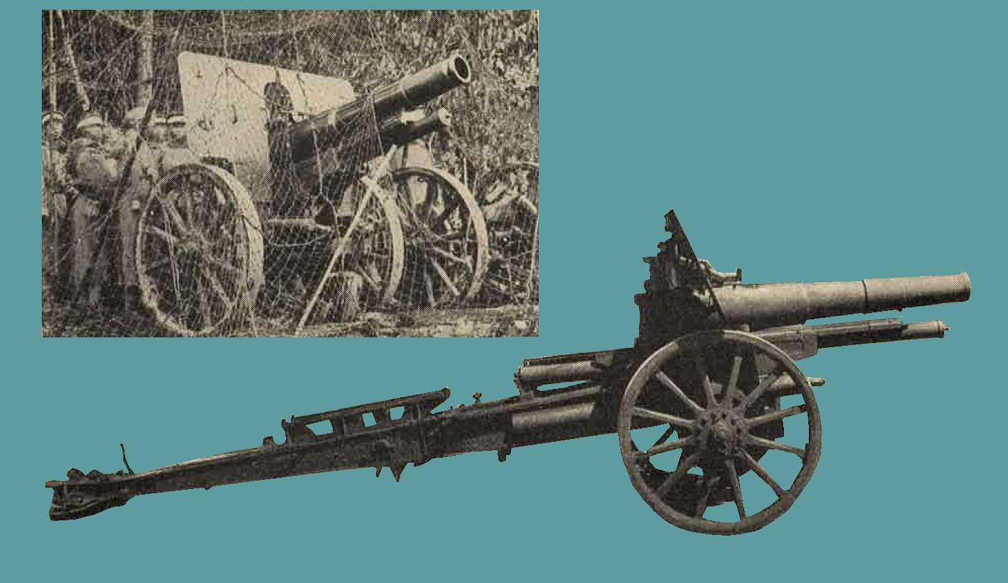
Figure 224. Two views of Model 4 (1915) 150-mm howitzer. |
(3) Ammunition. Ammunition is semifixed. The following types of projectiles have been reported:
- High explosive.
- Armor piercing.
- Sharpnel.
- Chemical.
Time fuzes are provided for the smoke, incendiary, and sharpnel projectiles. The standard point detonating (instantaneous and delay) fuzes are used with the HE and chemical shells.
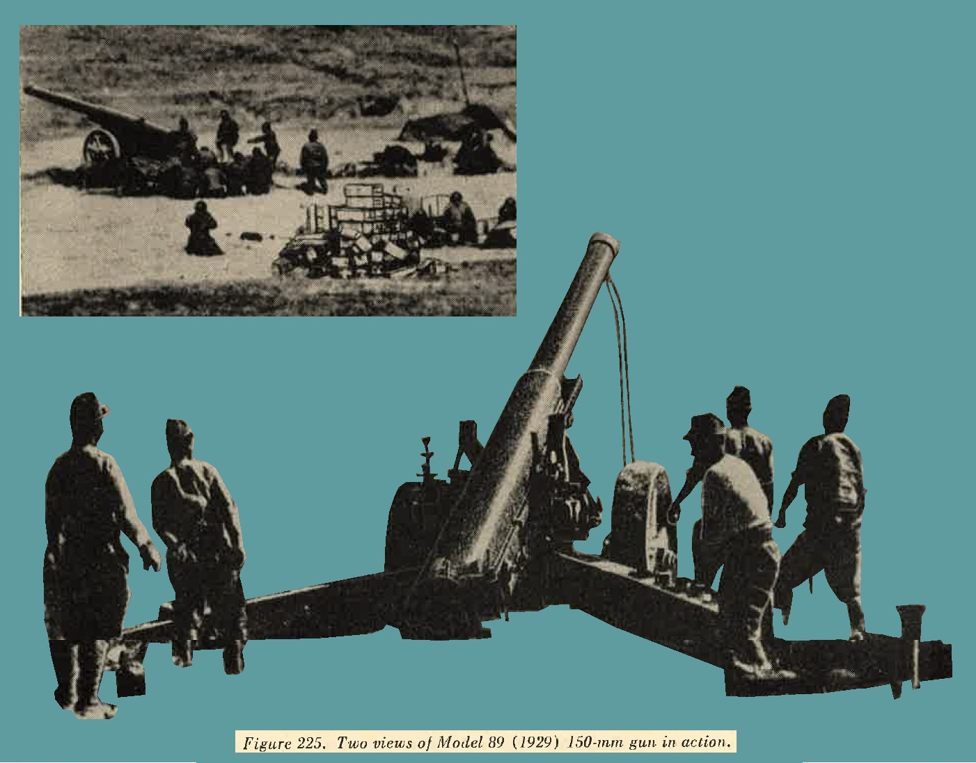
j. Model 89 (1929) 150-mm gun.
(1) General description. A tractor drawn weapon (figure 225) of improved design employed for long range fire. it is designated by the Japanese Army as a heavy field artillery piece. Although manufactured was commenced in 1929, it is believed that issue was not completed until 1937. For purposes of transportation the barrel is removed from the cradle and placed on a separate carriage. The weapon has a split trail, hydropneumatic recoil mechanism, and an interrupted thread block.
(3) Ammunition. AP, HE, Sharpnel, HE (long pointed shell). |
 |
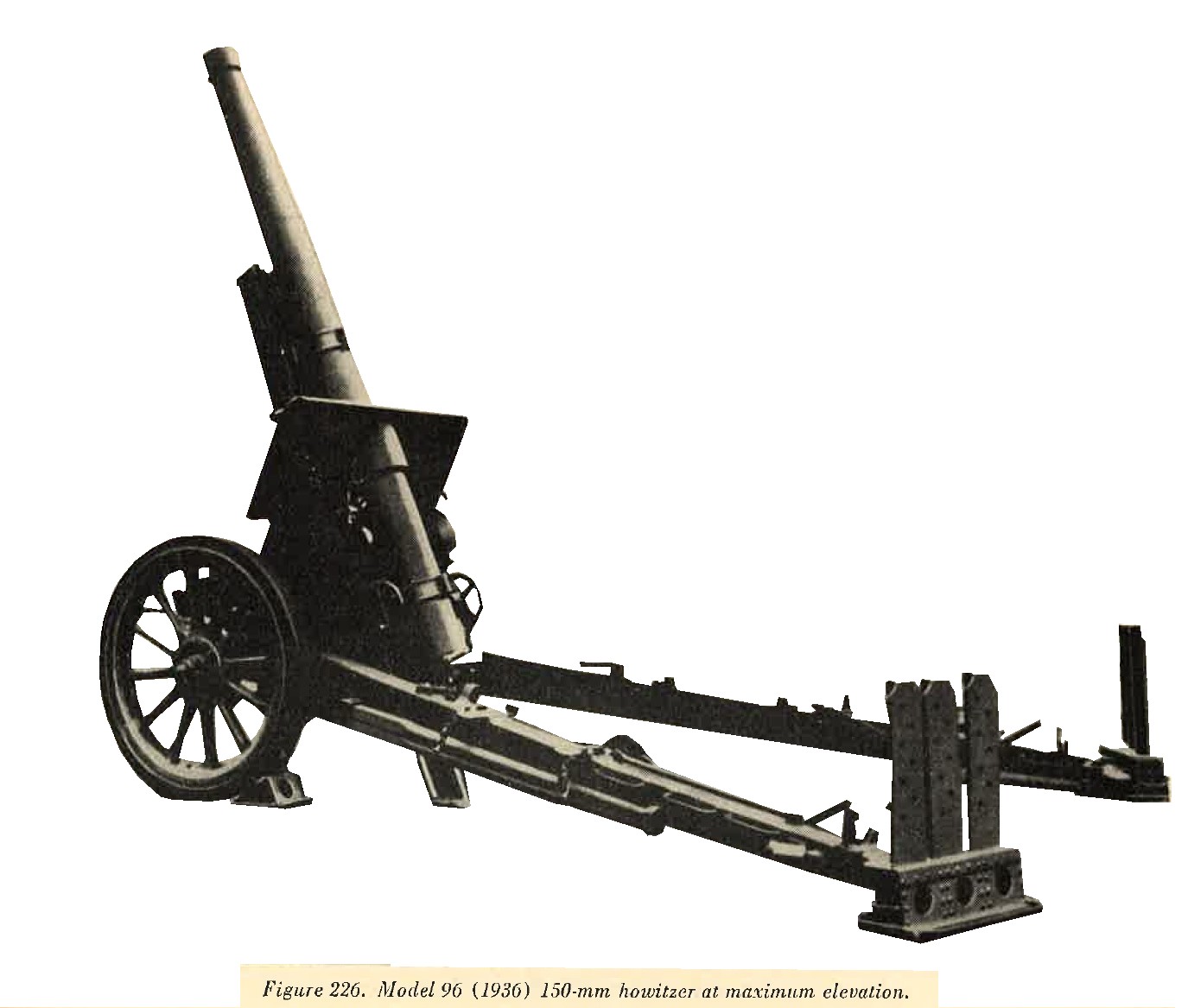
k. Model 96 (1936) 150-mm Howitzer.
(1) General description. A well designed and effective weapon (figure 226) which is, to date (1944) the most modern of its type known to be possessed by the Japanese. It is reported that three modifications exist. Variations, however, are believed to be extremely slight. Mounted on sturdy, rubber shod, wooden wheels, the weapon is normally tractor drawn. One of the outstanding characteristics is the extreme elevation of 75 degrees which can be obtained. This, however, can be used only when a deep loading pit is dug beneath the breech. It is probable that the weapon could not be fired at an elevation greater than 45 degrees without construction of such a pit. Other features are a long split trail, interrupted thread breechlock, and a hydropneumatic recoil mechanism.
(2) Characteristics.
(3) Ammunition. Semifixed; HE, AP, Sharpnel, smoke, incendiary tracer. |
 |
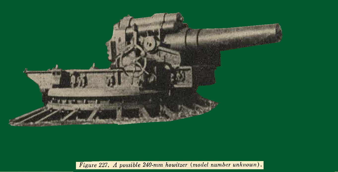
l. Model 45 (1912) 240-mm Howitzer.
It is reported that this piece has a maximum range of 11,000 yeards, firing a semifixed round weighing approximately 400 pounds. It is broken down and transported on 10 vehicles. (See figure 227).
m. Miscellaneous heavy artillery.
in recent years the Japanese have bought 17-cm, 21-cm and 24-cm weapons from Germany and therefore Japanese copies of these may be expected. In addition to the above, the following heavy artillery pieces have been reported but none have been captured, therefore the characteristics given below have not been confirmed.
| Caliber | Type | Length of bore | Muzzle velocity | Type of shell | Weight of shell | Maximum range | Elevation | Weight in action | Remarks |
| 24-cm | Railway gun | ----- | 3,560 ft/sec | HE | 440 lbs | 54,500 yrds | ----- | 35 tons | Several types reported |
| 30-cm | Howitzer M18 | 196 | 1,310 ft/sec | HE | 880 lbs | 12,750 yrds | 46 deg | 14.72 tons | Unconfirmed |
| 30-cm | Howitzer M18 | 324 | 1,140 ft/sec | HE | 1,100 lbs | 16,600 yrds | 48 deg | 19.76 tons | Do. |
| 41-cm | Howitzer (seige) | 538 | 1,760 ft/sec | HE | 2,200 lbs | 21,200 yrds | 45 deg | 80 tons | Do. |
3. WWII JAPANESE ANTIAIRCRAFT ARTILLERY.
a. Inroduction. It has been emphasized to the Japanese soldier that effective aircraft defense depends on the use of all arms. Many of the weapons primarilyt designed for ground action and previously described under infantry armament also are designed to perform an antiaircraft role.
(1) The new basic infantry weapon Model 99 (1939) 7.7-mm rifle (figure 228) has a rear sight, with arms calculated to give the rifleman the approximate lead required to hit a low flying plane.
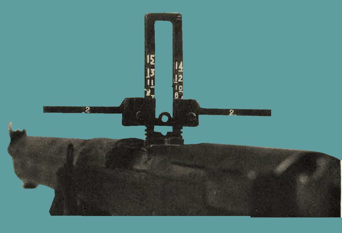
Figure 228. Rear sight on Model 99 (1939) 7.7-mm rifle.
(2) The Model 92 (1932) 7.7-mm heavy machine gun (figure 229) is provided with an antiaircraft adapter as illustrated in figure 229, and standard antiaircraft ring sights.
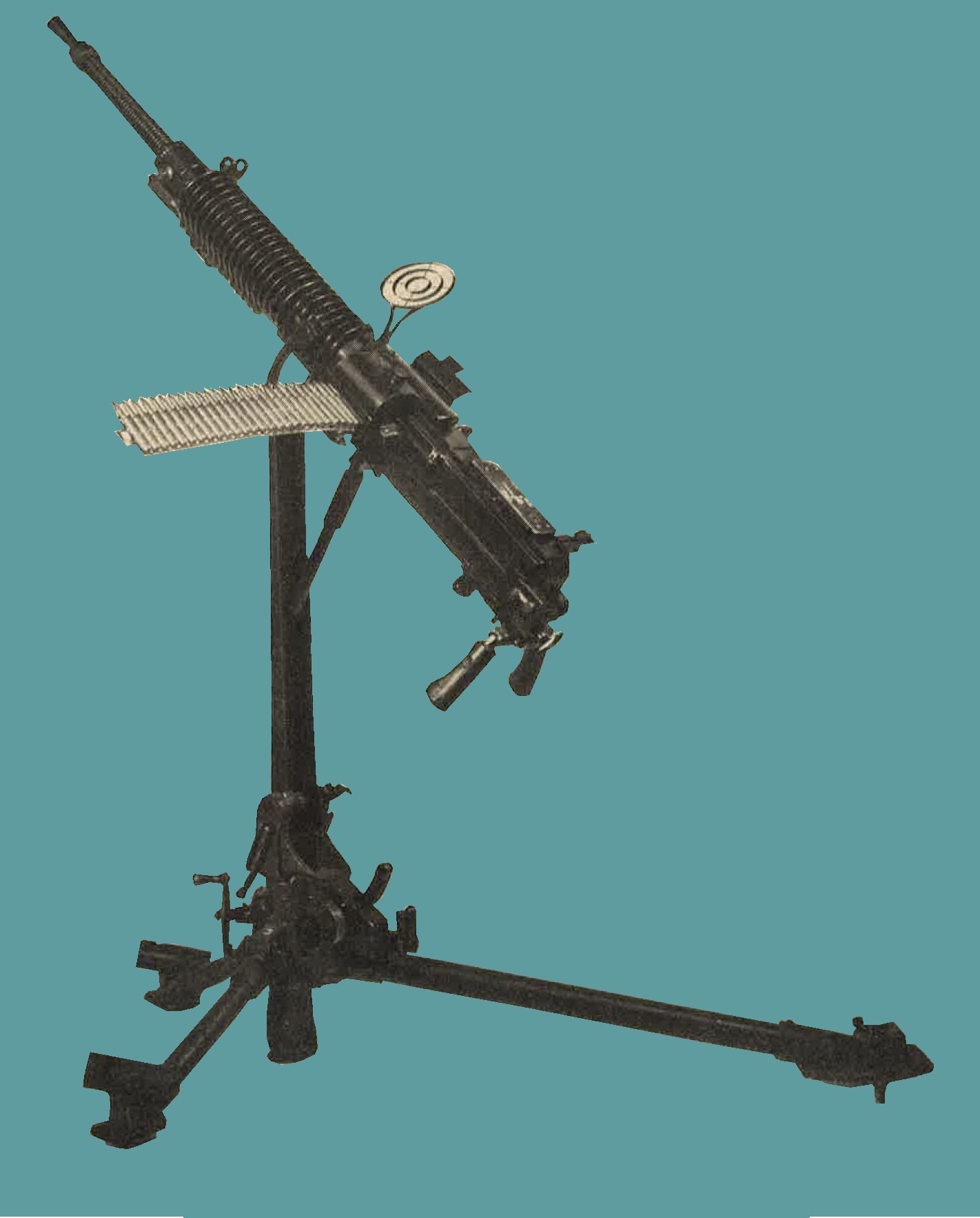
Figure 229. Model 92 (1932) 7.7-mm HMG with AA adapter.
(3) The Lewis type Model 92 (1932) 7.7-mm machine gun (figure 230) has a standard mount which can be adapted for antiaircraft defense (see figure 230)
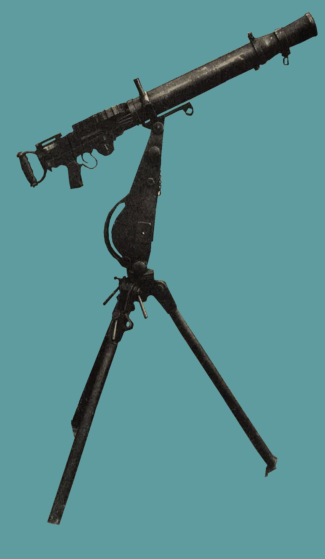
Figure 230. Model 92 (1932) 7.7-mm machine gun (Lewis type) in position for AA fire.
(4) The Model 93 (1933) 13-mm machine gun is shown in figure 231 in dual mount for antiaircraft fire.
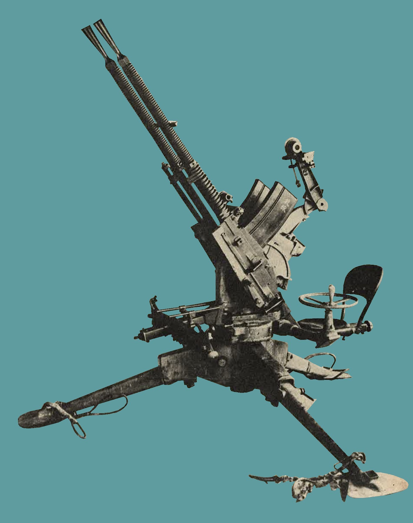
Figure 231. Model 93 (1933) 13-mm machine gun (dual mount).
(5) The Model 98 (1938) 20-mm AA/AT automatic cannon and probably the 70-mm barrage mortar (Chapter 9, Section II) have been designed principally for an antiaircraft role.
(6) In addition to the more common antiaircraft weapons described in detail on the following pages, 120-mm and 127-mm naval antiaircraft guns have been encountered. Th elatter in dual mounts.
(7) There are indications that Japanese heavy AA artillery is possibly more modern and a larger caliber than the standard 75-mm model 88, which is the only heavy antiaircraft weapon captured in quantity to date.
(8) Tabulated below are the estimated capabilities of Japanese aircraft weapons.
| NUM | CALIBER | WEAPONS | MAXIMUM RATE OF FIRE | MAXIMUM VERTICAL RANGE |
| 1 | 7.7-mm | Model 92 heavy machine gun | 450 | 4,000 |
| 2 | 7.7-mm | Model 92 (Lewis) machine gun | 600 | 4,000 |
| 3 | 13.2-mm | Model 93 machine gun | 450 | 13,000 |
| 4 | 20-mm | Model 98 automatic cannon | 200 | 12,000 |
| 5 | 25-mm | Model 96 naval automatic cannon | 300 | 14,000 |
| 6 | 40-mm | Vickers type | ----- | 14,000 |
| 7 | 75-mm | Model 88 gun | 15 | 30,000 |
| 8 | 105-mm | Model 14 gun | 10 | 36,000 |
| 9 | 127-mm | Model 89 gun | 10 | 40,000 |
Information concerning fire control equipment used with some of the weapons listed will be found in Chapter 10.
b. Model 96 (1936) type 2, 25-mm antiaircraft - antitank automatic cannon.
1. General description. This (Figure 232) is gas operated, air cooled, magazine-fed, full automatic,or semiautomatic machine cannon. It has been been found in dual and triple fixed mounts, emplaced customarily around air strips for antiaircraft defense. However, it is capable of 10 degree depression which makes it effective for direct fire against ground targets. Traverse and elevation are controlled by hand wheels.
2. Characteristics.
|
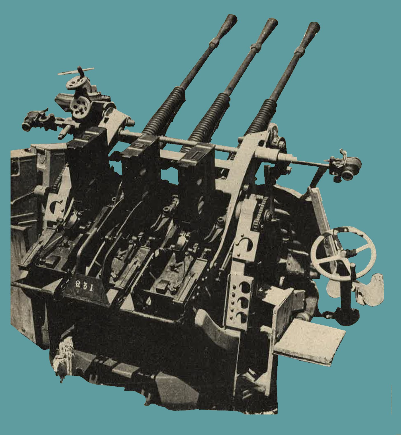
Figure 232. Rear view of Model 96 (1936) type 2, 25-mm AA/AT automatic cannon, triple mount. |
3. Ammunition. This weapon is furnished with high explosive tracer, high explosive, and armor piercing tracer ammunition.
c. 40-mm single and dual antiaircraft and antitank automatic cannon.
(1) General description. This weapon (figure 233) is a Vickers type recoil operated, water cooled, link belt fed, automatic or semiautomatic machine cannon. several of these have been captured. Single mounted guns were marked "Vickers - Armstrongs 1931", but the dual mounted guns were Japanese manufactured copies. Elevation and traverse are obtained by hand. The weapon is fitted with a telescopic calculating sight and an automatic fuze setter.
(2) Characteristics.
(3) Ammunition. Armor piercing high explosive, high explosive with time fuze, high explosive with point detonating fuze, and tracer. |
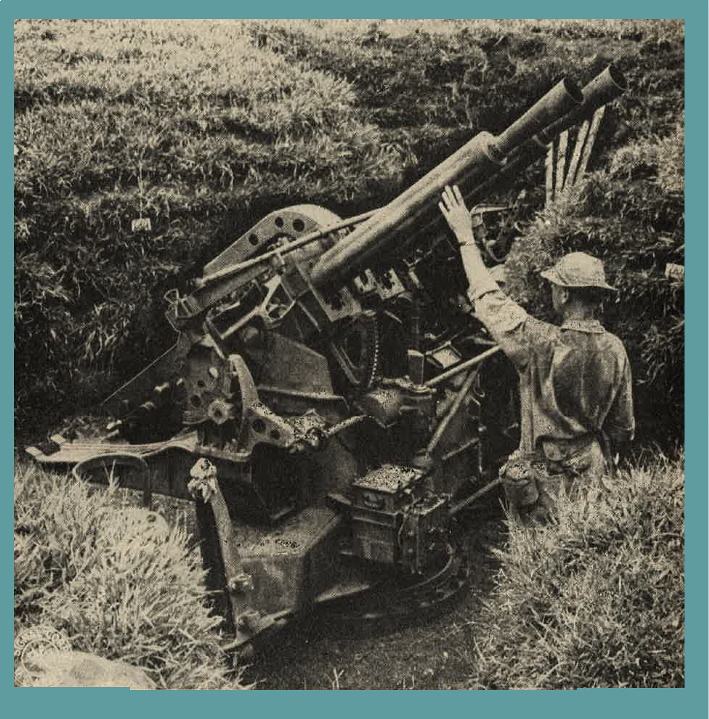
Figure 233. Dual mounted 40-mm Vickers type 40-mm AA/AT automatic cannon. |
d. Model 88 (1928) 75-mm antiaircraft gun.
(1) General description. This has been the standard Japanese mobile heavy antiaircraft weapon (figure 234). Specimens have been found on all airfields captured from the Japanese. It is a truck drawn weapon. For firing, the wheels are removed, and the gun is supported by five outriggers. During transit, the barrel is dropped back on the cradle extension and secured to the ends of two outriggers. The gun has a hydropneumatic variable recoil system and a semiautomatic horizontal, sliding wedge breech mechanism. Fire control instruments captured indicate that the older system of transmitting corrections to the gun pointers vocally is still in use. However, evidence is on hand that an electrical data transmission system and operation by the "Matched Pointers" method is used sometimes. This gun has been used against ground targets.
(2) Characteristics.
(3) Ammunition. High explosive, sharpnel, and incendiary. |
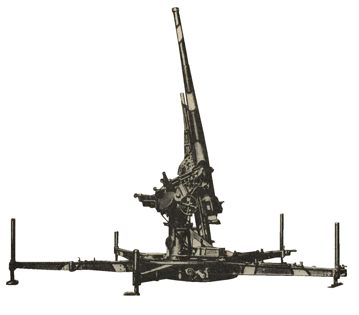
Figure 234. Model 88 (1928) 75-mm antiaircraft gun. |
e. Model 14 (1925) 105-mm antiaircraft gun.
(1) General description. This is the heavist mobile Japanese antiaircaft weapon (figure 235) in use at present (1944). As originally designed, it was not satisfactory, and probably has been redesigned by this time. It has a pedestal mount, horizontal sliding breechblock, and a hydropneumatic recil system. In firing position the wheels are detached and the gun rests on six outriggers. Thiry to 45 minutes are required to prepare the gun for action. The fuze setter is continuous and automatic.
(2) Characteristics.
(3) Ammunition. High explosive. |
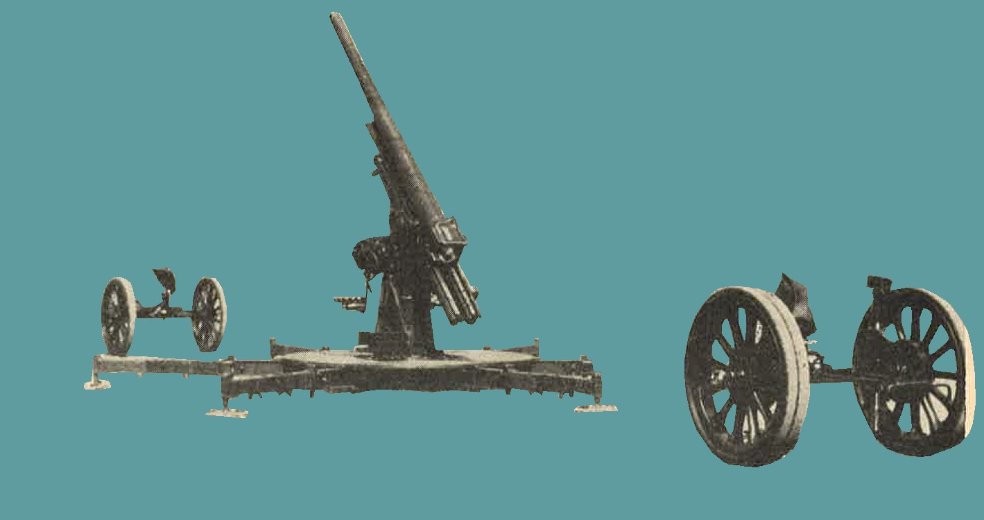
Figure 235. Model 14 (1925) 105-mm antiaircraft gun showing detachable wheels used for transport of piece. |
4. JAPANESE NAVAL WEAPONS.
a. General In all areas captured from Japanese, naval guns have been found installed for coastal and antiaircraft defense. These weapons have been of standard naval design, and in many cases appear to have been removed complete (including turret, mounting, etc.) from the decks of the ships. It is known that the Japanese have recovered the armamentfrom beached ships and transferred them to land posiitons.
Since they are on pedestal mounts with wide traverse, they not only are used for coastal defense but also may be brought to bear against inland targets. On the following pages are found examples of the naval guns which are most likely to be encountered. Of these weapons the Model 10 (1921) 3-inch gun has been most frequently installed. In addition to thoseweapons described, guns of 127-mm (5 inch) and 8 inch calibers have been captured. The 127-mm guns have been found mounted in pairs in turrets which permit antiaircraft fire.
b. Model 10 (1921) 3-Inch gun.
(1) General description.
The Japanese refer to this weapon (figure 236) as the "8-cm, 40 caliber, high angle gun". actual measurements show it to be 76.2-mm (3 inch). A dual purpose piece of pedestal mount, it is used as antiaircraft as well as coastal defense. To compensate for muzzle preponderance, an equilibrator is mounted in the pedestal. The recoil system is hydropneumatic, and the breechblock is the sliding wedge type. A noticeable feature is the unusually long recoil cylinder on the top of the tube.
(2) Characteristics.
(3) Ammunition. High explosive. |
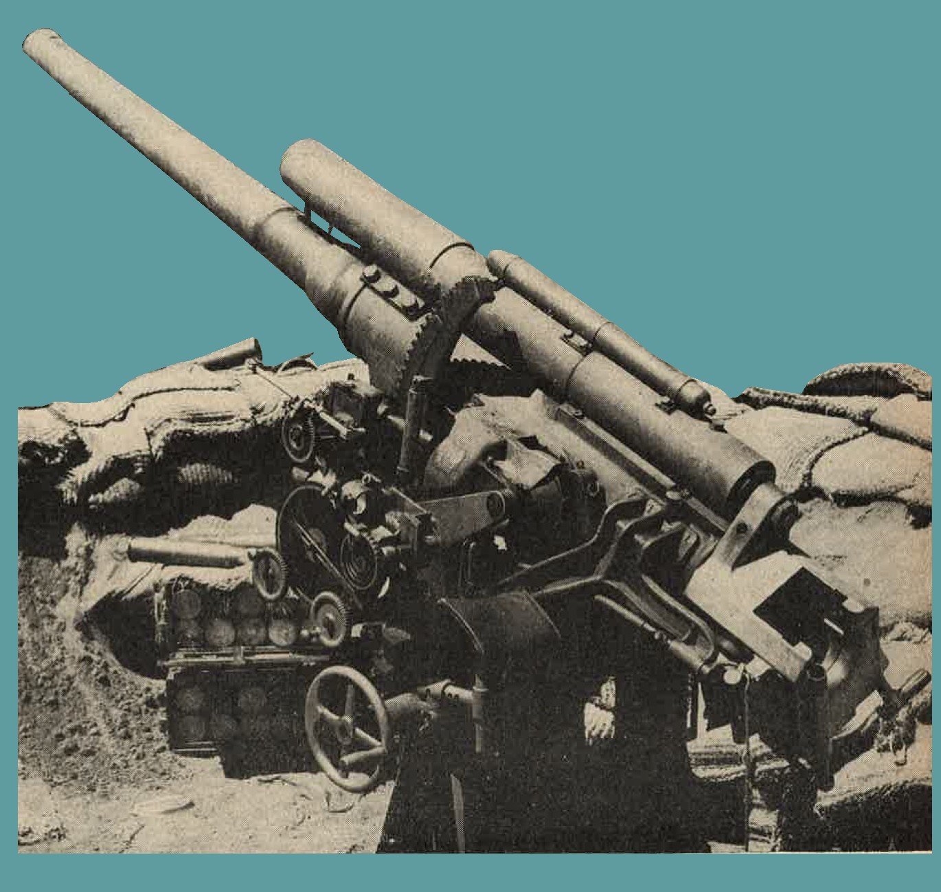
Figure 236. Model 10 (1921) 3-inch gun. |
c. Model 3 (1914) 12-cm Naval gun.
(1) General description.
Guns of this type (figure 237) have been encountered on a number of islands in the Pacific area. No provision has been made on the gun illustrtated in figure 237 to provide for use as an antiaircraft weapon, but other weapons of this caliber allegedly are munted for such purposes. It has a hydropneumatic recoil system and an interrupted thread breechblock.
(2) Characteristics.
(3) Ammunition. Separate loading high explosive with a cartridge case used for obturation. |
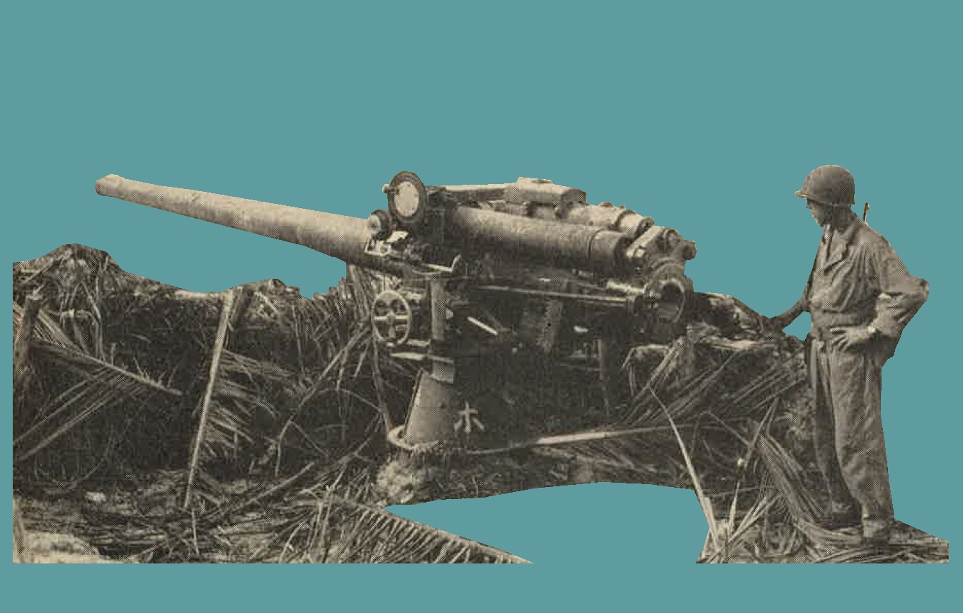
Figure 237. Model 3 (1914) 12-cm naval gun. |
d. Model 3 (1914) 14-cm naval gun.
(1) General description.
An orthodox type of naval gun and pedestal mount (figure 238) which has been used as a coastal defense weapon. It has been found both with a shield and mounted in a hand operated turret (casemate). It has a hydropneumatic recoil system and truncated cone, interrupted thread breechblock.
(2) Characteristics.
(3) Ammunition. Separate loading ammunition is used. The prokectiles recovered were high explosive, with fuzes designed for use against vessels. |
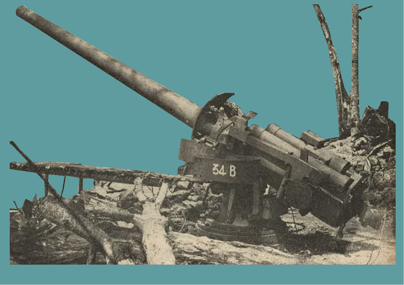
Figure 238. Model 3 (1914) 14-cm naval gun. |
SECTION V - WWII JAPANESE CHEMICAL WARFARE (PART 1).
1. WWII JAPANESE GAS MASKS
a. General. All the known models of gas masks used by Japanese military forces are of the air hose and separate canister type. Rubber stoppers are provided to permit sealing of the canister when it is in use to protect the contents against moisture. IN general the Japanese gas masks afford good protection against the common types of war gases; their facepieces, however, are uncomfortable when fitted to the average occidental face. The American canisters can be ftted to these masks for better protection aganist hydrocyanic acid (AC) and cyanogen chloride (CC) gas than the Japanese canister gives. The existence of horse gas masks of the damp mask type has been reported.
b. Japanese Army gas mask "Model 95".
It has a Khaki stockinette covered facepiece (figure 258) with molded tissot tube and circular eyepieces with removable threaded rims. The eyepieces ae made of glass. A total of 6 elastic straps secure the mask to the head. The Khaki colored canister is approximately 6 inches high, 5 inches wide and 2 3/4 inches thick. The carrier is a rectangular canvas bag. A rubberized hood is sometimes attached to this mask to protect head and shoulders.
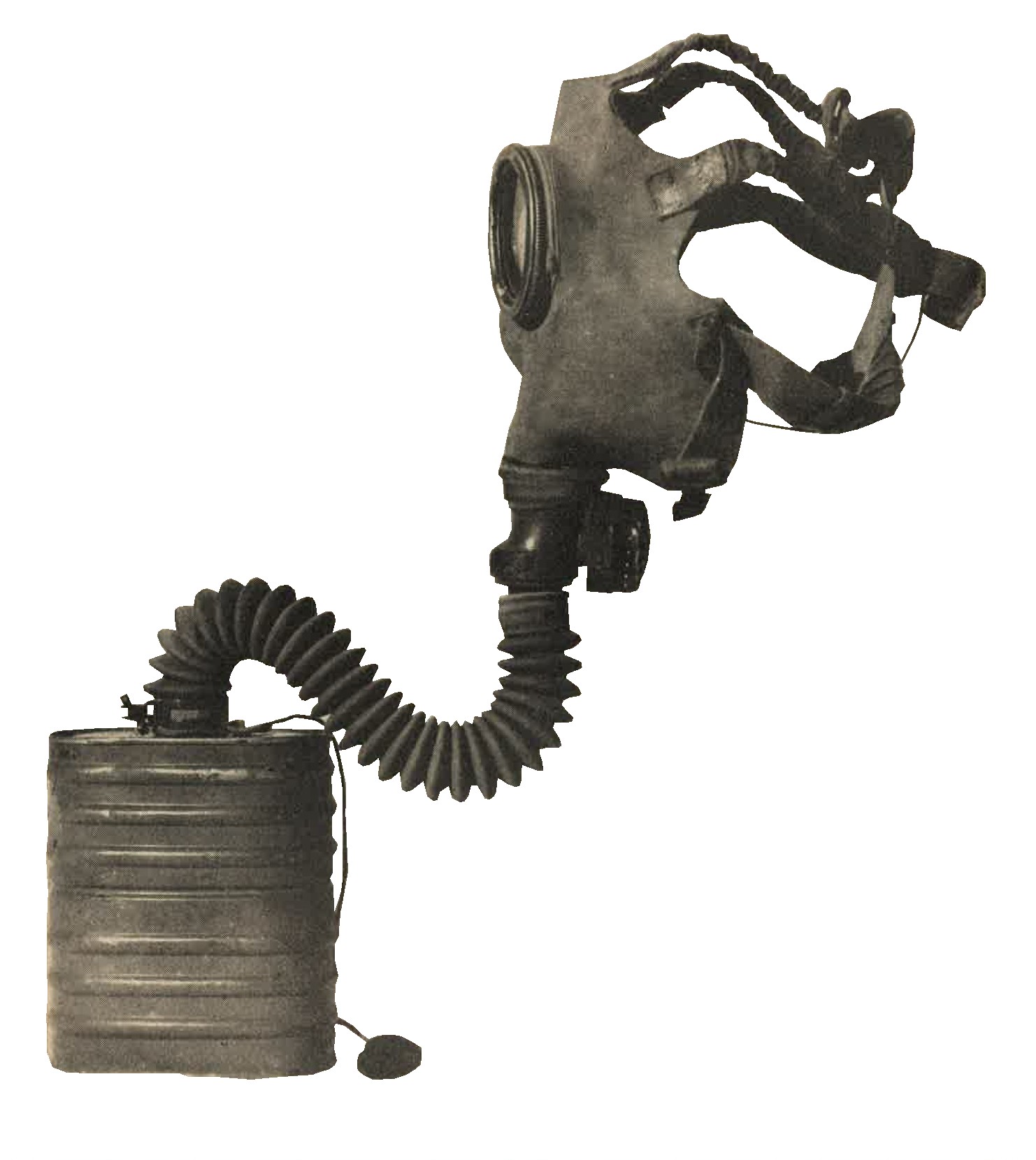
Figure 258. Army gas mask Model 95. |
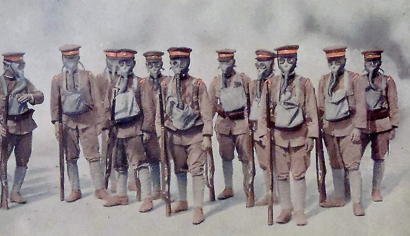
Figure 258-a. Postcard of WWII Japanese soldiers wearing gas masks. |
c. Japanese Army gas mask "Model 99".
Similar in appearance to the "Model 95" (figure 259), the gas mask is fitted with a rubber nosepiece held inside the facepiece by a stud, and has a short canister only about 4 1/2 inches high.
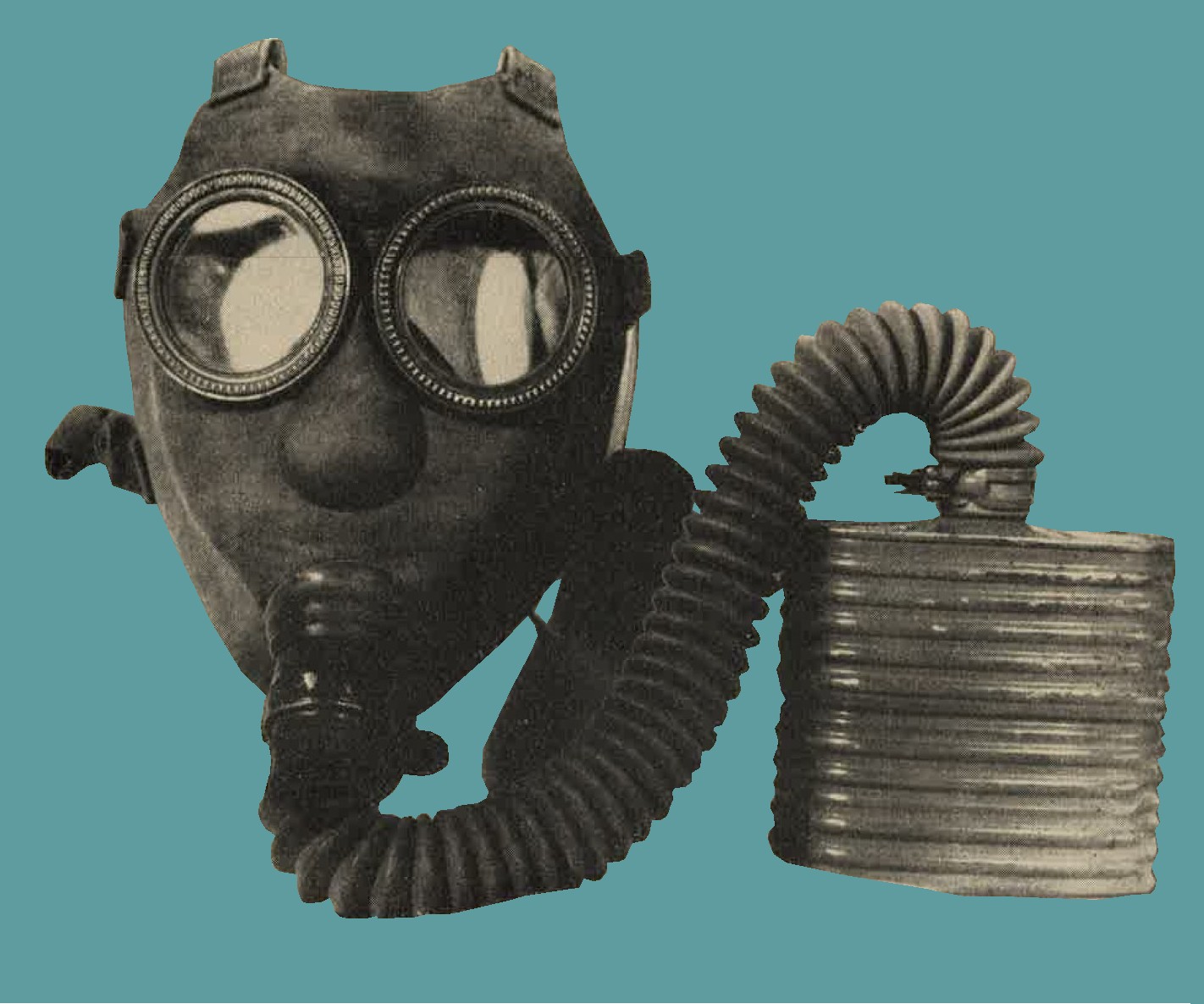
Figure 259. Army gas mask "Model 99". |
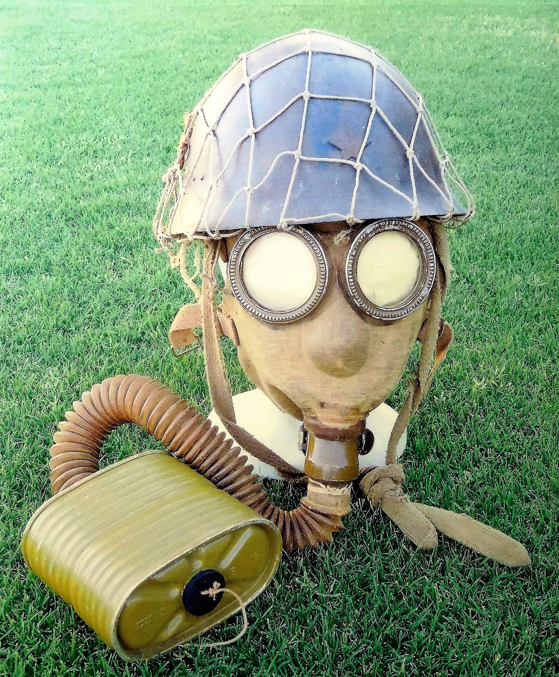
Figure 259-a. Type 99 army gas mask with helmet. Manufactured by Fujikura. 1944. |
d. Japanese Civilian gas mask type 1, Model A (improved).
This gas mask (figure 260), although originally designed for civilian use, also is issued to Army personnel. The facepiece is tan colored with molded tissot tube and circular, glass, eyepieces with fixed rims. The tan colored canister is approximately 4 3/4 inches high, 5 1/4 inches wide and 2 3/4 inches thick. The carrier is a small rectangular canvas bag with a 1 1/2 inch diameter hole in the bottom.
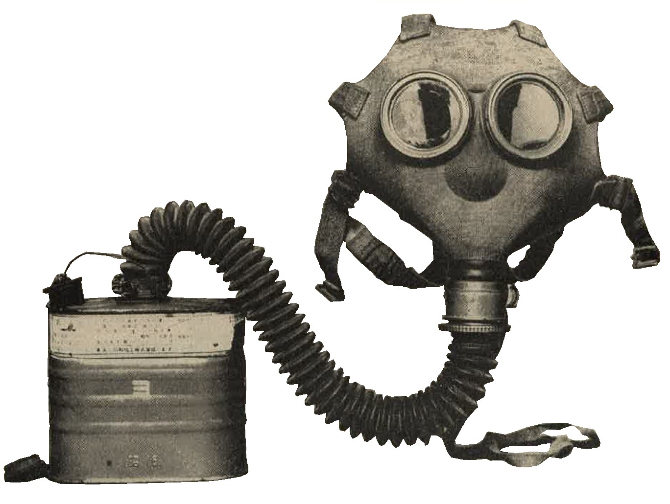
Figure 260. Civilian gas mask Type I, Model A (Improved). |
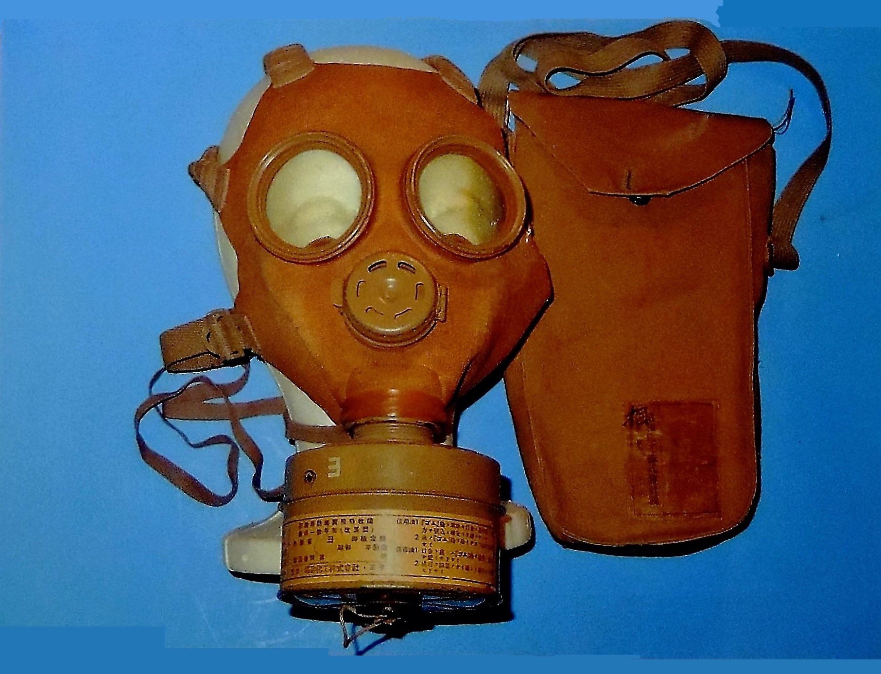
Figure 260-a. Civilian gas mask with carrying case. |
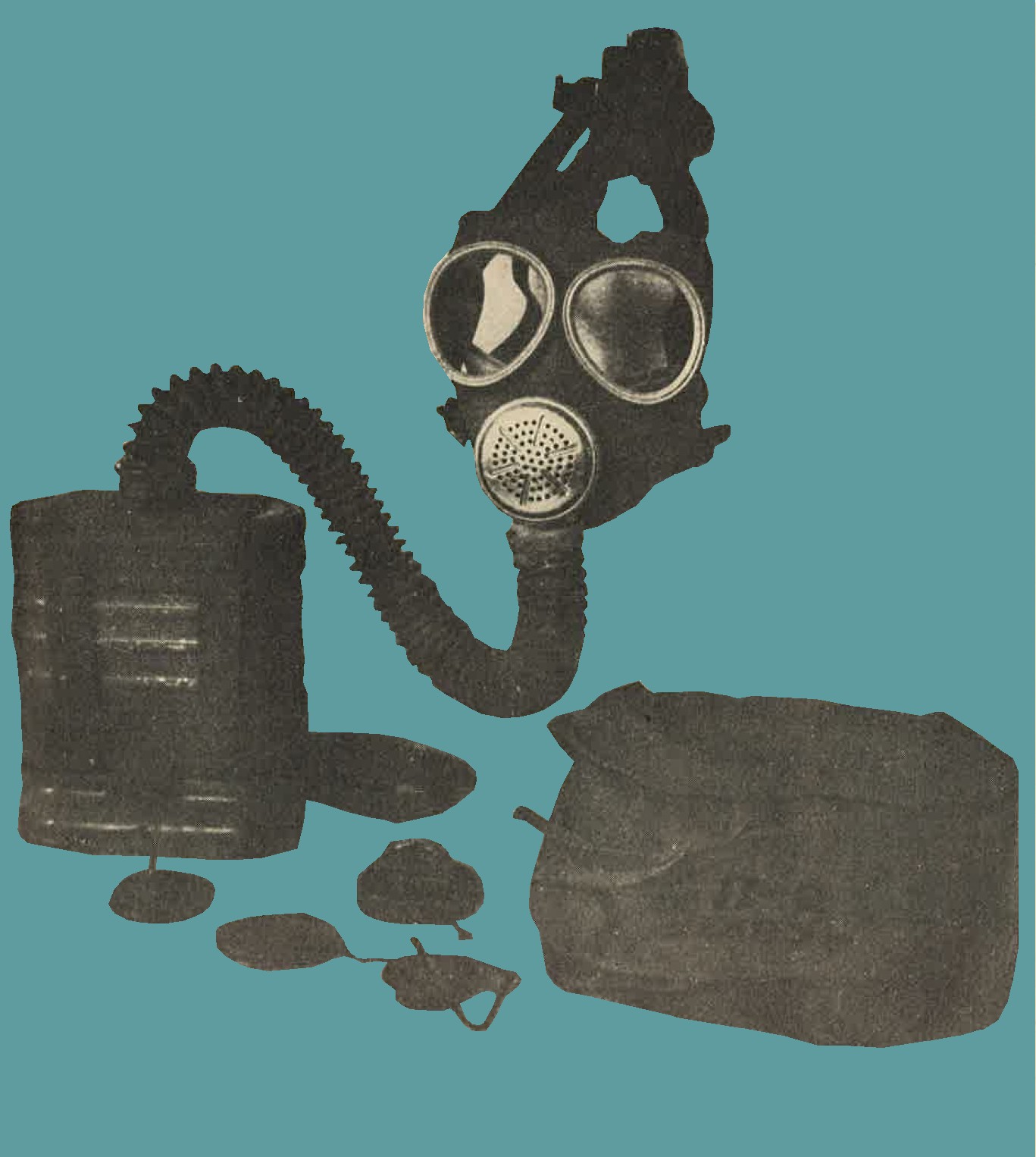
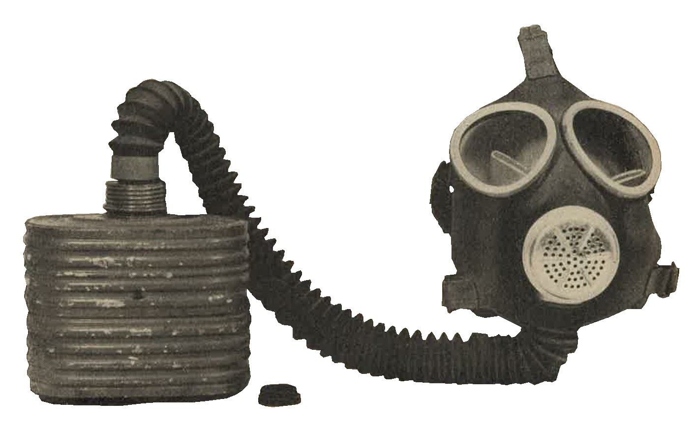
Figure 262. Navy gas mask Model 93, No. 3. |
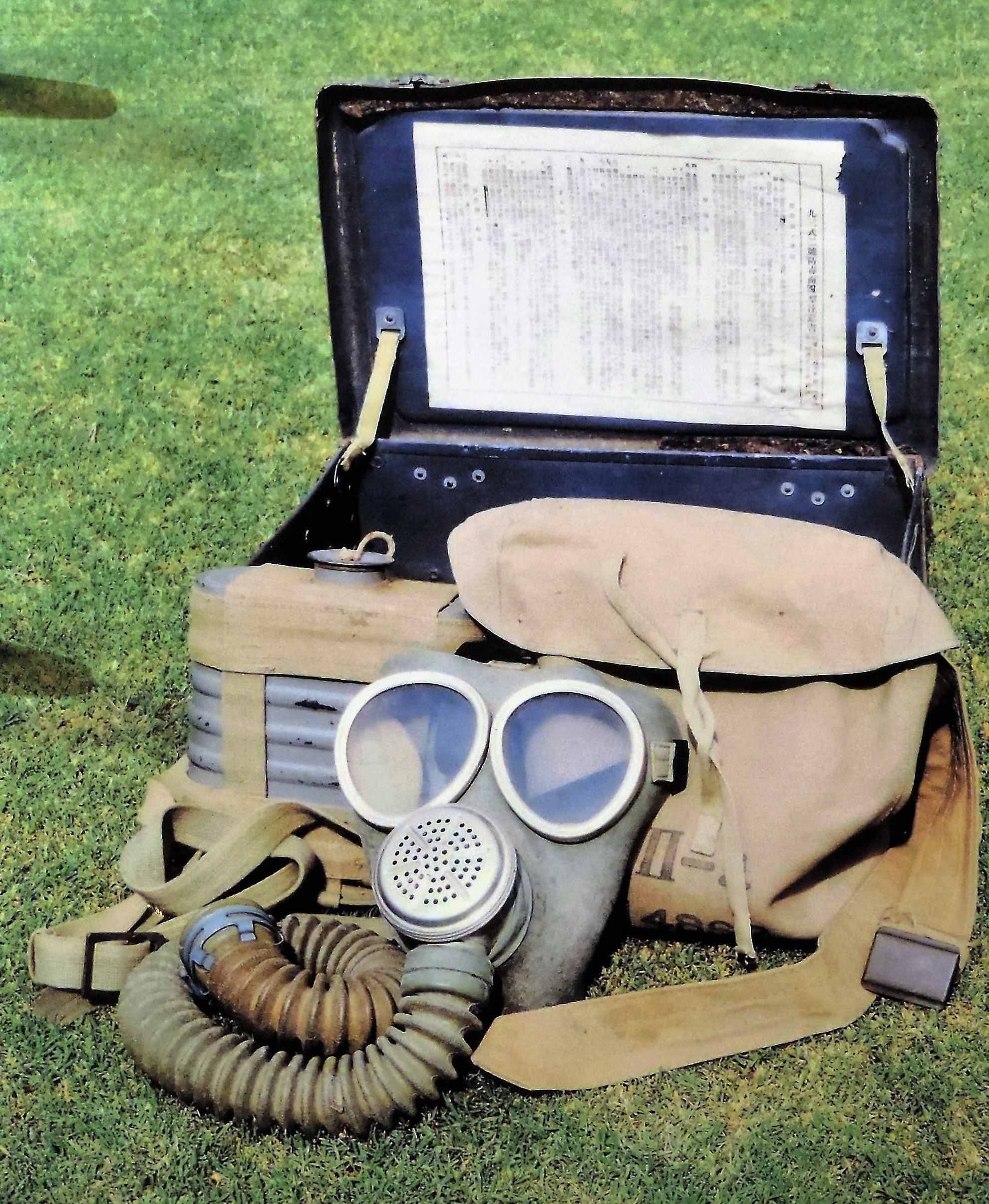
Figure 262-a. Navy gas mask Model 93 with all accessories. |
The color photograph shows the entire ensemble wich includes; The mask itself. Rubber body with glass lenses. Complete with the filter. All painted battleship gray. The canvas carrying bag which is worn by the soldier in the field. Also included is the metal transport box. This box remained on the ship and kept the gas mask protected during travel.
2. WWII JAPANESE GAS MASK ACCESSORIES.
The carriers of most army gas masks are provided with a packet of antifog discs (Figure 263), a container for antifreeze liquid (Figure 264), a hinged metal clamp for closing the air hose, and a cleaning rag. In addition...
FIX BREAK IN PAGE
b. Bleaching powder pouch. The pouch (Figure 270), measuring approximately 12 inches by 7 inches, is made of rubberized fabric and is provided with a tie string, carrying strap, and a pocket containing several pieces of cotton gauze. The pouch holds approximately 5 ounces of bleaching powder, presumably for use in decontamination of articles of individual equipment.
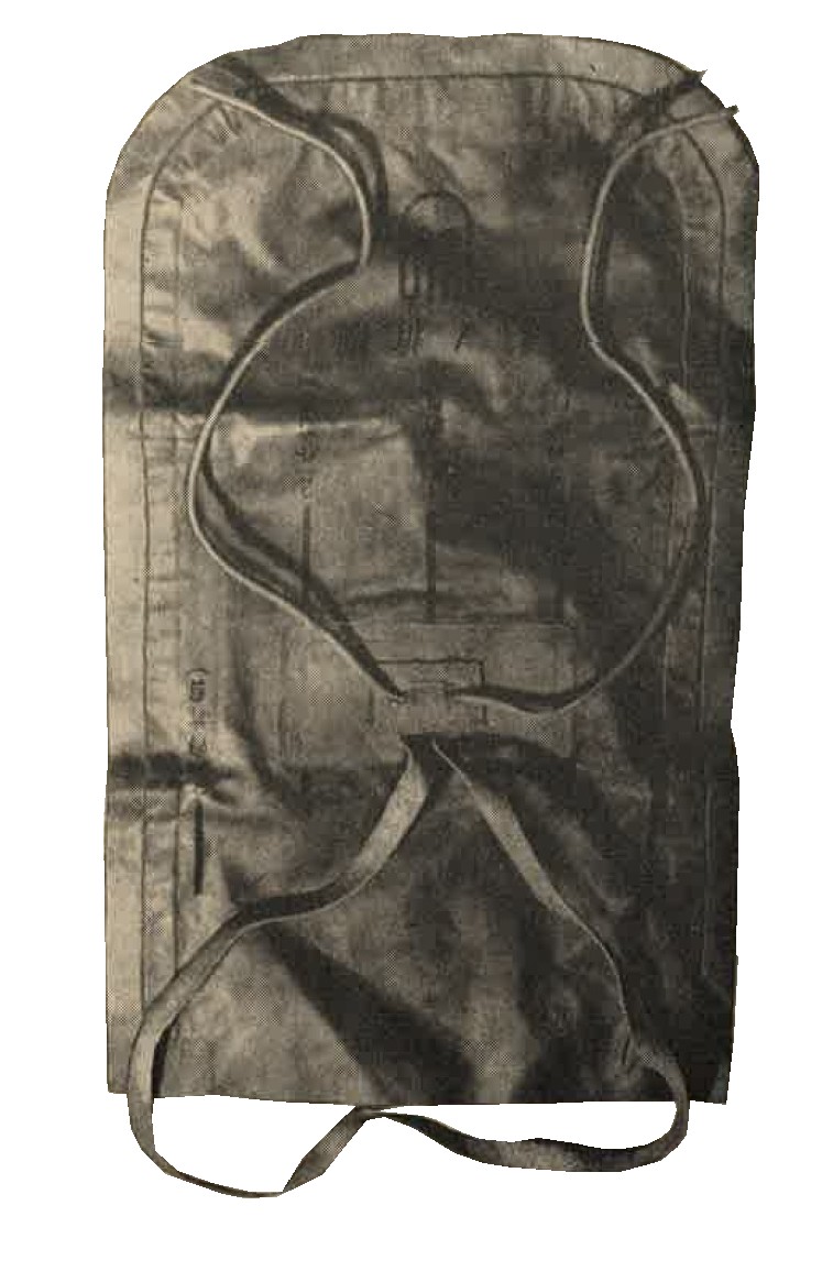
Figure 270. WWII Japanese army bleaching powder pouch.
c. Decontamination agent, No 1. A cylindrical sheet metal container, 2 1/2 inches high and 2 1/2 inches diameter, with one blue band around the casing (figure 271) contains approximately 0.33 pounds crystalline potassium permanganate.
Figure 271. Decontaminating agents (1) No1. (2) No2. (3) No3. (4) No4.
d. Decontamination agent, No 2. A rectangular sheet metal box, 4 1/2 inches high and 4 3/16 inches square (see above figure 271) with two blue bands around the casing, contains approximately 2.25 pounds of flaked sodium hydroxide.
e. Decontamination agent, No 3. A rectangular sheet metal box, 13 1/4 inches high, 7 3/4 inches wide and 5 3/4 inches thick, with three green bands around the casing (see above figure 271) contains approximately 15 pounds of chloride of lime.
f. Decontamination agent, No 4. A cylindrical sheet of metal can, 2 3/4 inches high, 2 7/16 inches in diameter, with four blue bands around the casing (see above figure 271) contains a spherical glass ampule wrapped in cotton gauze. The ampule holds approximately 1.8 ounces of a yellow liquid consisting of a 20 percent solution of chlorine in carbon tetrachloride.
g. Uses. These decontamination agents are used as follows:
| AGENT | FUNCTION |
| No. 1 and No. 2. | For decontamination of tear gases and vomiting gases. |
| No. 3. | For decontamination of blister gases. Used to refill the pouch. |
| No. 4. | For decontamination of blister and vomiting gases. |
The effectiveness of these agents is not known, but is considered comparable with similar Allied agents.
5. WWII JAPANESE GAS DETECTORS.
a. Blister gas detection satchel. The square satchel, 6 inches x 6 inches, with a carrying strap, contains detector papers, a small box of calcium hypochlorite, a box containing 16 glass ampulets of detector material, and a supply of small flags for marking contaminated areas. The white detector material contained in the ampules turns red in contact with blister gases.
b. gas detector kit. The kit (figure 272) comprises a light metal cylindrical barrel, 10 1/4 inches long and 2 1/2 inches in diameter; a rubber bulb and tubbing; and a set of five detector tubes. When testing for war gases the five detector tubes are placed inside the barrel and held in the holes of a rubber stopper provided for this purpose. Air is then drawn through the tubes by means of the rubber bulb. The kit is contained in a wooden carrying case.
Figure 272. Gas detector.
c. Gas detector kit (Navy model). The kit (figure 273) comprises a rubber, bulb-actuated, metal air pump and set of three detector tubes. Air is drawn through the detector tubes. It is said that the presence of blister gases, and carbon monoxide can be determined by color changes of the indicator materials contained in the detector tubes. The kit is carried in a grey metal case.
Figure 273. Navy model gas detector kit.
SECTION V - WWII JAPANESE CHEMICAL WARFARE (PART 2).
OFFENSIVE EQUIPMENT.
1. WWII JAPANESE MARKING OF CHEMICAL MUNITIONS.
Indications are that the Japanese attention to war gases has been confined largely to the well known blister, tear, vomiting, etc., gases. In addition, agents for the production of screening smokes are manufactured. The Japanese distinguish between ordinary smoke and toxic, ot tear, clouds by referring to the latter as "special smoke". The type of agent contained in a chemical munition is usually identified by a color band according to the following scheme:
| GAS TYPE | COLOR BAND |
| Choking gases | Blue |
| Tear gases | Green |
| Blister gases | Yellow |
| Vomiting gases | Red |
| Blood and nerve poisons | Brown |
| Screening smoke | White |
Chemical projectiles and most chemical aerial bombs are generally grey in color. Filled shells have a red hand at the nose, followed by a blue band to indicate special handling because of the chemical filling. According to the best evidence available, the type of war gas filling is indicated by a colored band in accordance with the above scheme. This band is about twice as wide as any other band on the shell. A narrow yellow band is believed to indicate a HE burster change, while a white band indicates that the projectile is constructed of steel.
2. WWII JAPANESE GAS SHELLS AND BOMBS.
a. General.
The 90-mm mortar and the 81-mm mortar are believed to have chemical munitions, as is a reported 150-mm mortar, but shells containing these fillings have not been captured. Likewise, the 105-mm gun and 150-mm howitzer shells probably have a chemical filling. The following shells and bomb are definetely known to be filled with war gases,
b. Japanese 50 kg aerial gas bomb.
Overall length 45 inches, body diameter 7.5 inches. Total weight 110 pounds, filling 50:50 lewsite mustard mixture, gray colored with one yellow and one white band between nose and lug and one yellow band between tail and lug.
c. Japanese 75-mm blister gas shell.
Weight 12.5 pounds. Filling 1.4 pounds 50:50 lewsite mustard mixture. Markings; red band followed by blue band (indicating CW filling) on nose, one white and one wide yellow band on body, which indicates blister gas filling.
d. Japanese 75-mm vomiting gas shell.
Weight 13.25 pounds. Filling 0.4 pounds diphenylcyanarsine. Markings, red band followed by blue band on nose. Yellow band below burrelet indicating HE filling, then a wide red band indicating vomiting gas and finally a white band indicating a steel shell.
3. WWII JAPANESE FRANGIBLE HYDROCYANIC ACID (AC) GRENADES.
See Section II, Chapter 9, for description.
4. WWII JAPANESE GAS CANDLES.
Most Japanese gas and smoke candles of the stationary or hand thrown type are fired by means of a matchhead fuze and scratcher block. All Japanese self projecting gas and smoke candles (Figures 274, 275, 276, and table) are composed of an outer container equipped with a
|
|
Figure 275. Medium vomiting gas candle.
Tear gas candle table
| Num | Description | Length | Diameter | Body color | Markings | Weight (Lbs) | Filling | Notes |
| 1 | Tear gas candle | 7.2 | 2.2 | Grey | Green band | 0.5 | CN mixture | Main filling nitrocellulose wafers containing CN. |
| 2 | Small tear gas candle | 5.5 | 2.5 | do | do | .4 | do | Believed to be obsolete. |
Vomiting gas candle table
| Num | Description | Length | Diameter | Body color | Markings | Weight (Lbs) | Filling | Notes |
| 1 | Light vomiting gas candle. | 7.2 | 2.2 | Grey | Red band | 0.6 | DC | Metal ring handle at bottom. |
| 2 | Heavy vomiting gas candle | 9.8 | 4.4 | Brown | do | 4.4 | do | Metal ring hand;e at bottom. Under cover 16 taped vent holes. Separate compartments for fuel mixture under smoke charge. |
| 3 | Medium vomiting gas candle | 8.8 | 4.4 | do | do | 3.3 | do | Metal ring handle at bottom. Fixed hinged metal prong at side. |
| 4 | Light self projecting vomiting gas candle | 7.9 | 2.0 | do | do | 1.5 | do | Projectile has carboard casing. |
| 5 | Heavy self projecting vomiting gas candle | 8.2 | 2.0 | do | do | 2.2 2.6 |
do | Projectile has sheet metal casing and wooden bottom |
5. WWII JAPANESE SMOKE GRENADES.
a. 50-mm small shells for grenade discharger type 89.
See Section II, Chapter 9, for description.
b. WWII Japanese Rifle smoke grenade.
See Section II, Chapter 9, for description.
c. Frangile smoke grenade white.
See Section II, Chapter 9, for description.
6. WWII JAPANESE SMOKE CANDLES.
Figure 277. "Type 94" small smoke candle (white label). |
Figure 278. "Type 99" self projecting smoke candle. |
 |
 |
SMOKE CANDLE TABLE
| Num | Designation | Length (inches) | Diameter (inches) | Body color | Markings | Weight (approx) | Smoke mixture | Notes |
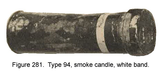
| 1 | Type 94 small smoke candle A | 6.9 | 2.2 | Grey | White label | 2.2 | Berger type | Metal ring handle at bottom probably an early model. |
| 2 | Do | 6.9 | 3.2 | Green or Brown | do | 2.2 | do | No handle. may be wrapped in paper with printed instructions. Probably a later model. |
| 3 | Type 94 large smoke candle A | 18 | 6 | Grey | do | 44 | do | Hinged wooden handle at top, attached to metal band around casing. Small screw cap lid. |
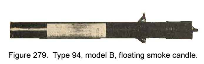
| 4 | Type 94 floating smoke candle B | 31.2 | 3.1 | Grey or Brown | White label or white band | 15.4 | HC type | Metal ring bracket for float around upper part. "10 year pattern" hand grenade time fuze fits opening on top closed by wing screw plug. |
| 5 | 1 Kilogram smoke candle "Revision 4" | 8.3 | 2.1 | Tinplate | White labels top and side | * 2.2 | Berger type | Naval smoke candle. |
| 6 | 1 Kilogram smoke candle "Revision n7" | 8.3 | 2.1 | Do | White labels top and side | * 2.2 | HC type | Naval smoke candle. Igniter removable. |
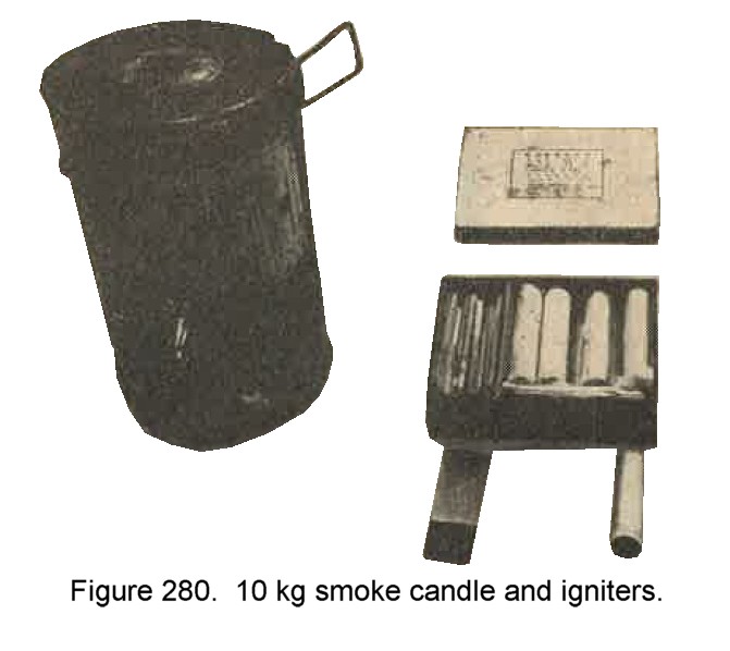
| 7 | 10 Kilogram smoke candle | 9.5 | 6 | Grey | Labels on top and side | * 22 | Berger type | Naval smoke candle. Igniter well fitted with wooden plug. Igniters packed separately. |
| 8 | 30 Kilogram smoke candle | 9.5 | 10.5 | Do | do | * 64 | do | Naval smoke candle. Igniter well closed by wooden plug. Igniters are packed separately. The candle may be fitted with a float. |
| 9 | Experimental self projecting smoke candle | 8.2 | 2.1 | Grey or Brown | May have white band | 1.5 | HC type | Sometimes wrapped in paper. Projectile has cardboard casing and short igniter tube. |
| 10 | Type 99 self projecting smoke candle | 8.2 | 2.1 | Do | White Japanese characters on side | 2.9 | do | Projectile has sheet metal casing. Igniter tube extends whole length of projectile. Under bottom cover metch board exposed through slot. |
* As weight varies considerably, figures shown are merely the conversion of the indicated kilogram weight to pounds.
7. WWII JAPANESE AERIAL INCENDIARY BOMBS.
Army incendiary ombs are painted grey whereas the HE bombs are black. Navy type bombs , both HE and incendiary, are painted grey. Red and silver tail struts designate an incendiary filling.
a. 1 KG smoke incendiary/antipersonnel bomb, Army type.
Characterized as follows:
| 1. | Overall length | --------- | 10.25 inches. |
| 2. | Body diameter | --------- | 3 inches. |
| 3. | Color and markings | --------- | White rubber nose, black body, white tail cone and fins. |
| 4. | Main charge | --------- | Red phosohorus. |
Used in conjunction with demolition bombs as a marker. On explosion antipersonnel effect by fragmentation of case iron body. b. Japanese 32 kg incendiary bomb.
Characteristics are as follows:
| 1. | Overall length | --------- | 24.4 inches. |
| 2. | Body diameter | --------- | 5.75 inches. |
| 3. | Total weight | --------- | Approximately 70 pounds. |
| 4. | Filling | --------- | Phosphorus filled steel pellets. |
| 5. | Color | --------- | Grey. |
| 6. | Markings | --------- | Silver band on nose and silver tail fin tips. |
c. Japanese 50 kg incendiary bomb.
Characteristics are as follows:
| 1. | Overall length | --------- | 3 feet 9 inches. |
| 2. | Body diameter | --------- | 7.75 inches. |
| 3. | Weight | --------- | Approximately 101 pounds. |
| 4. | Filling | --------- | Rubber pellets and phosphorus in carbon disulfide. |
| 5. | Color | --------- | Grey |
| 6. | Markings | --------- | One yellow and one white namd. |
d. Japanese 50 kg incendiary bomb, Army type 100.
Characteristics are as follows:
| 1. | Overall length | --------- | 3 feet 4 inches. |
| 2. | Body diameter | --------- | 7 inches. |
| 3. | Filling | --------- | Rubber pellets and phosphorus in carbon disulfide. |
| 4. | Color and markings | --------- | Grey body and tail, yellow and white bands just forward of suspension lug. |
This bomb is differentiated from the 50 kg incendiary bomb described in "c" above by a longer tail cone with a rounded apex.
e. Japanese 60 kg solid oil bomb, Navy type.
Characteristics are as follows:
| 1. | Overall length | --------- | 3 feet 6 1/2 inches. |
| 2. | Filling | --------- | Normal filling mixture of paraffin wax and kerosene but a filling consisting of pellets made of rubber-like incendiary material also exists. |
| 3. | Color and markings | --------- | Grey body and tail, red tail struts. |
f. Japanese 60 kg incendiary thermite bomb, Navy type.
Characteristics are as follows:
| 1. | Overall length | --------- | 3 feet 4 inches. |
| 2. | Body diameter | --------- | 8 inches. |
| 3. | Filling | --------- | Electron containers filled with thermite. |
| 4. | Color and markings | --------- | Grey body and tail, red tail struts. |
g. Japanese 250 kg HE/incendiary bomb.
| 1. | Overall length | --------- | 5 feet 9 inches. |
| 2. | Body diameter | --------- | 12 inches. |
| 3. | Weight | --------- | Approximately 550 pounds. |
| 4. | Filling | --------- | HE and about 750 small metal cylinders filled with incendiary substance. |
| 5. | Color and markings | --------- | Painted grey with a red band on tail and a silver band on end of nose. |
8. OTHER INCENDIARIES.
a. one half kilogram incendiary grenade.
See Section II, chapter 9, for description.
b. Japanese Incendiary grenade "Molotov cocktail".
See Section II, chapter 6 for illustration and complete description.
c. Japanese 90-mm mortar projectile.
Characteristics are as follows:
| 1. | Weight | --------- | Approximate 11.5 pounds. |
| 2. | Filling | --------- | Approximate 2.2 pounds phosphorus in carbon disulfide and rubber pellets. |
| 3. | Markings | --------- | Red band followed by blue band on nose, one yellow and one white band on body. |
d. Japanese 50-mm grenade discharger projectile, incendiary.
See Section II, Chapter 0, for description.
e. Japanese 75-mm incendiary shell, for Model 41 (1908) infantry gun.
| 1. | Weight | --------- | Approximately 14.5 pounds. |
| 2. | Filling | --------- | 22 oz., rubber pellets impregnated with a solution of phosphorus in carbon disulfide. |
| 3. | Markings | --------- | Blue - Grey projectile, red band below fuze. |
f. Japanese Incendiary stick grenade.
See Section II, Chapter 0, for description.
9. WWII JAPANESE FLAME THROWERS.
a. Flame thrower Type 93.
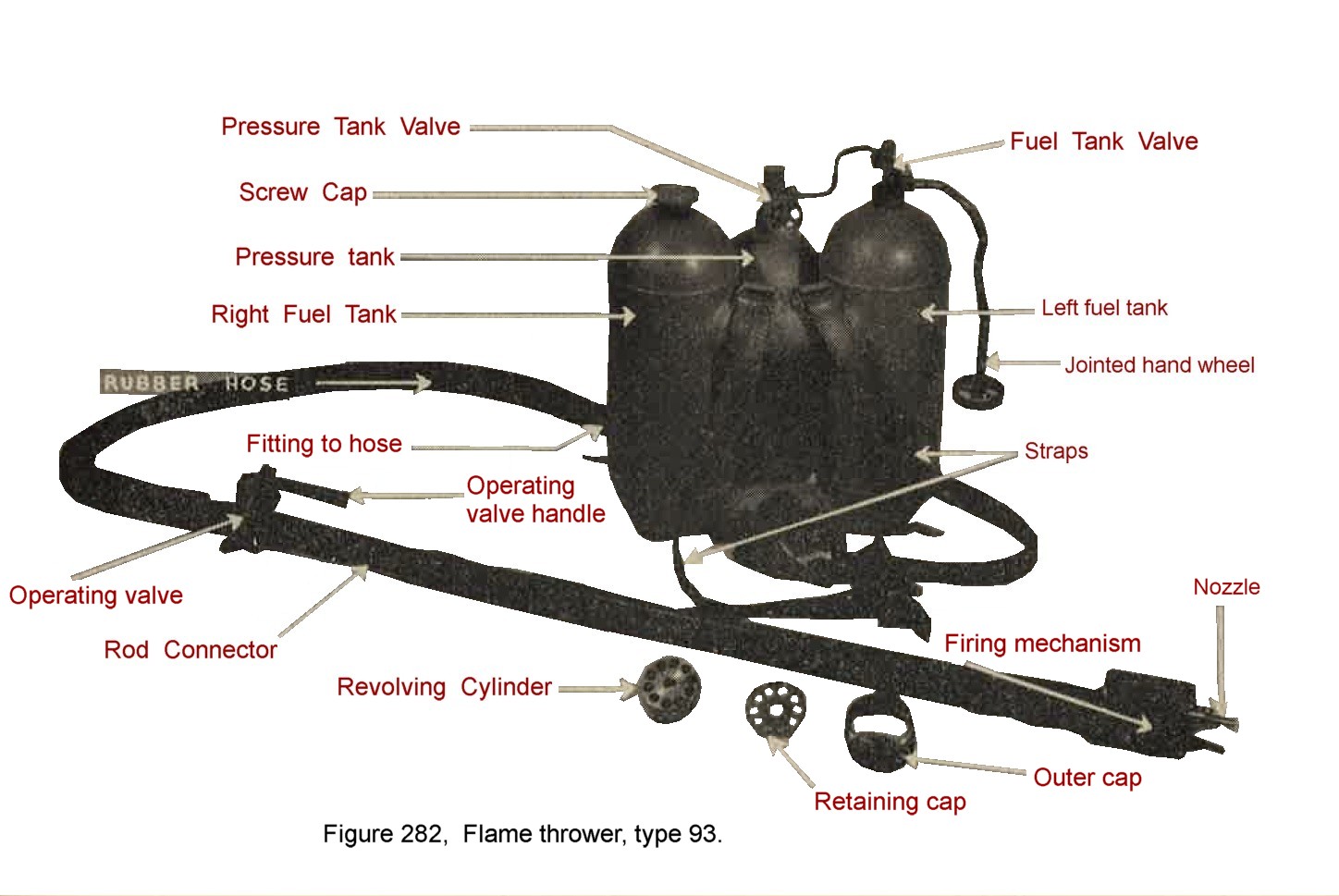
The fuel unit comprises 2 fuel tanks and a nitrogen pressure cylinder. Ignitionof fuel jet is effected by flash from a blank cartridge. ten of which are loaded in the revolving cylinder located at nozzle end of flame gun (See figure 282). The firing mechanism is actuated by operating handle which controls fuel ejection valve. Characteristics are as follows:
b. WWII Japanese Flame thrower Type 100.
Very similar to type 93 flame thrower. The fuel units of the two types are identical as are range and duration of flame. The differences are found in the flame guns as follows:
Japanese WWII flame thrower comparison table
| TYPE 93 | TYPE 100 | |
| Over-all length | 47 1/8 inches | 35 1/2 inches |
| Weight | 10 pounds | 8 1/2 pounds |
| Nozzel outlet tip | Fixed | Removable |
| Diameter of cartridge | 0.44 inch | 0.484 inch |
| Chambers of revolving cylinder | 10 | 10 |
c. Pyrotechnichs See Chapter 10.