CHAPTER 9 (9a - 9b) - WEAPONS

SECTION I - INTRODUCTION.
- In general, the development of Japanese weapons may be divided into periods, each of which follows
a war.
- The progenitors of current Japanese weapons, as well as some of the weapons still in use, were designed
between 1905 and 1912. a few models were modified in 1914 - 1915. Developments of the First World War were
noticeable in a group of weapons developed in 1921 and 1922. Then in 1925 began a great program of redesign
which finally included all Japanese weapons of every description.
- All categories of artillery were redesigned between 1925 and 1936. Infantry mortars were redesign
between 1929 and 1939, and automatic weapons, with many new weapons added, between 1932 and 1939.
- Although no weapon designed in 1940 is known, a modern, efficient 47-mm gun was produced in 1941,
and it is possible that the design of this weapon was influenced by the Nomonhan Incident when Japanese
and Russian border forces fought for 24 days in 1939. It is believed that other new designs, specially
anti-aircraft artillery, have made their appearance.
- as a ressult of early Japanese successes during WWII, various United States, Dutch and British weapons are found in use by the Japanese. In one or two cases the Japanese have copied captured weapons exactly. In others, tehy have manufactured ammunition to use in the captured artillery.
SECTION II - WWII JAPANESE INFANTRY WEAPONS.
1. WWII JAPANESE PISTOLS, REVOLVERS AND RIFLES.
a. General.
(1) All known Japanese rifles and carbines are of Arisaka design. Immediately after the Ruso-Japanese War, Model 38 (1905) 6.50mm Rifle was introduced and all subsequent rifles and carbines have adhere to this design. Later models have a folding monopod attached to the lower band. The design closely follows tha Mauser and is simple and sturdy. The safety mechanism is an unusual feature.
(2) The only known Japanese military revolver is a very clumsy copy of a Smith and Wesson top break revlver. This weapon was introduced in 1893.
(3) The first Japanese military magazine pistol was designed by General Nambu. Despite its supeficial resemblance to the German Luger, the action of the Nambu pistol is unique. The original design was improved in the model 14 (1925) pistol.
(4) The Model 94 (1934) pistol is a crude attempt to make a small pistol along general Browning lines.
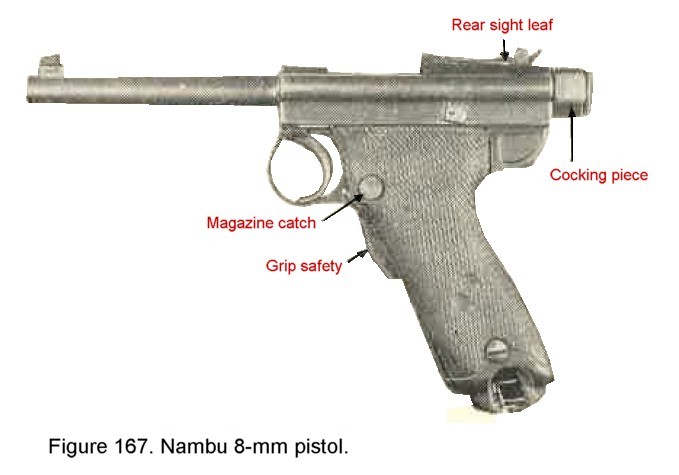
b. Nambu 8-mm pistol.
(1) General description.
This is a semiautomatic, recoil-operated, magazine fed hand weapon (figure 167). It is equipped with a grip safety below the trigger guard. The markings
 on the right side of the receiver read "Nambu Model". In addition to the
markings, the weapon is easily identified by the recoil-spring housing (a bulge to the left side of the receiver)
and the adjustable rear sight. This is a leaf with an open V notch sliding on a ramp and is graduated from
100 to 500 metes. The weapon may be equipped with a wooden holster, also designed to be used as a shoulder stock
when attached to the heal of the butt.
on the right side of the receiver read "Nambu Model". In addition to the
markings, the weapon is easily identified by the recoil-spring housing (a bulge to the left side of the receiver)
and the adjustable rear sight. This is a leaf with an open V notch sliding on a ramp and is graduated from
100 to 500 metes. The weapon may be equipped with a wooden holster, also designed to be used as a shoulder stock
when attached to the heal of the butt.
(2) Characteristics.
(3) Ammunition. Rimless ball cartridges are provided and are interchangeable in the Model 14 and the Model 94 pictols described in the following pages. |
 |
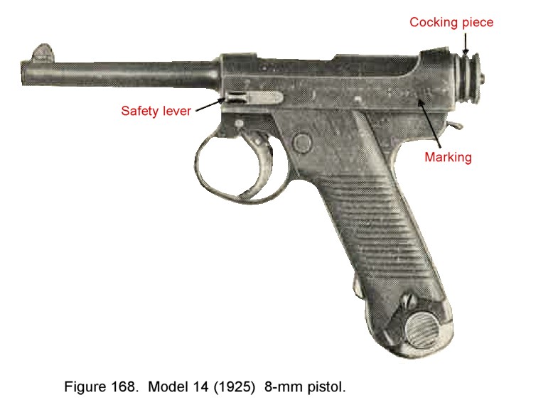
c. Model 14 (1925) 8-mm pistol.
(1) General description The Model 14 (1925) 8-mm pictol is a semiautomatic, recoil operated, magazine fed hand weapon (figure 168). It is a development of the Nambu 8-mm pistol. markings
 on the left side of the receiver read "14th year Model". The front sight is a blade
type sight and the rear sight is a non-adjustable open V notch. The safety lever is moved to the forward
position for "fire" and rearward for "safe". An unusually large trigger guard permits firing with a
gloved hand.
on the left side of the receiver read "14th year Model". The front sight is a blade
type sight and the rear sight is a non-adjustable open V notch. The safety lever is moved to the forward
position for "fire" and rearward for "safe". An unusually large trigger guard permits firing with a
gloved hand.
(2) Characteristics
(3) Ammunition Rimless ball cartridges are provided and are interchangeable in the Nambu and the Model 94 pistols. 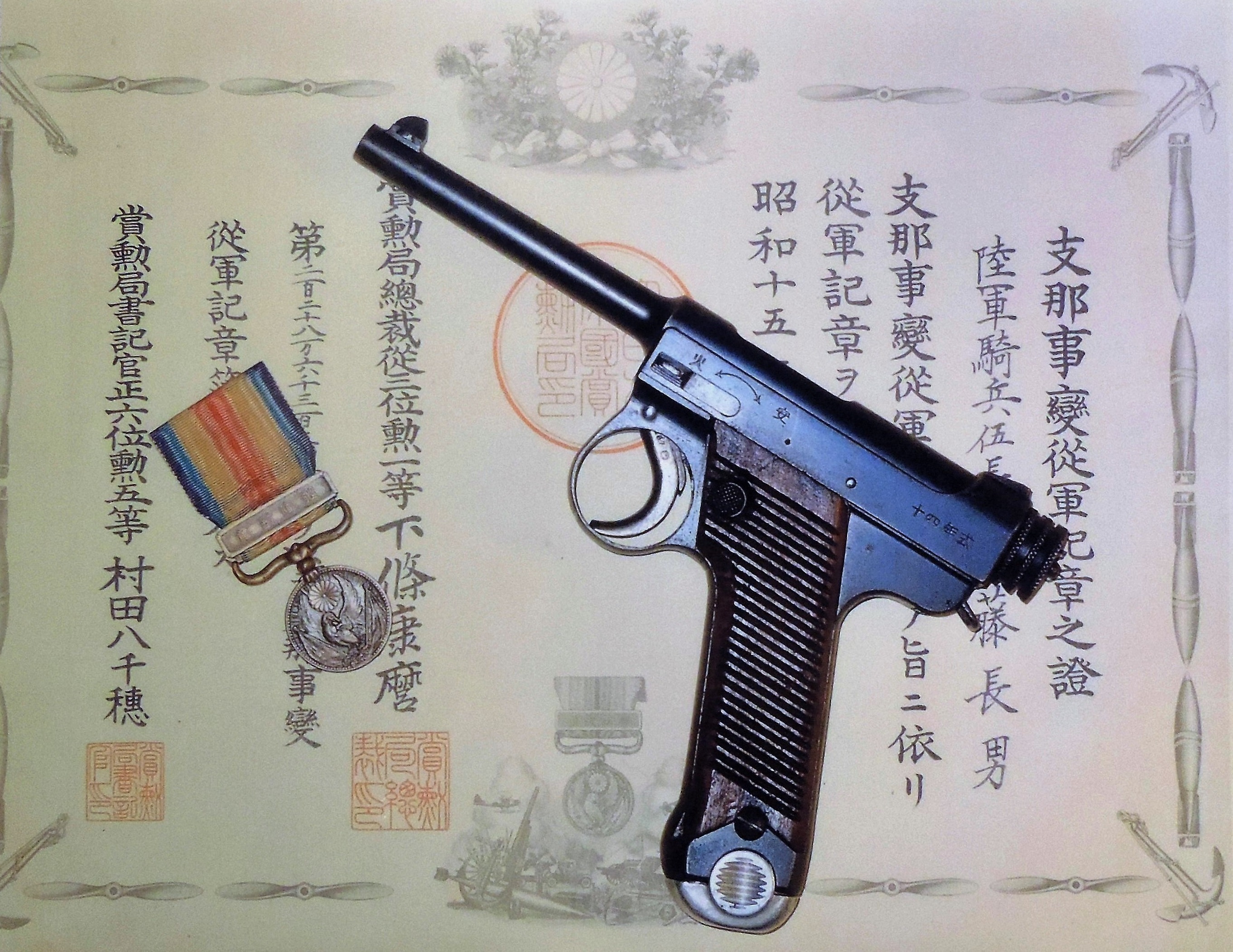
Figure 168-a. Type 14 Nambu with 1937 award document for China campaign. |
 |
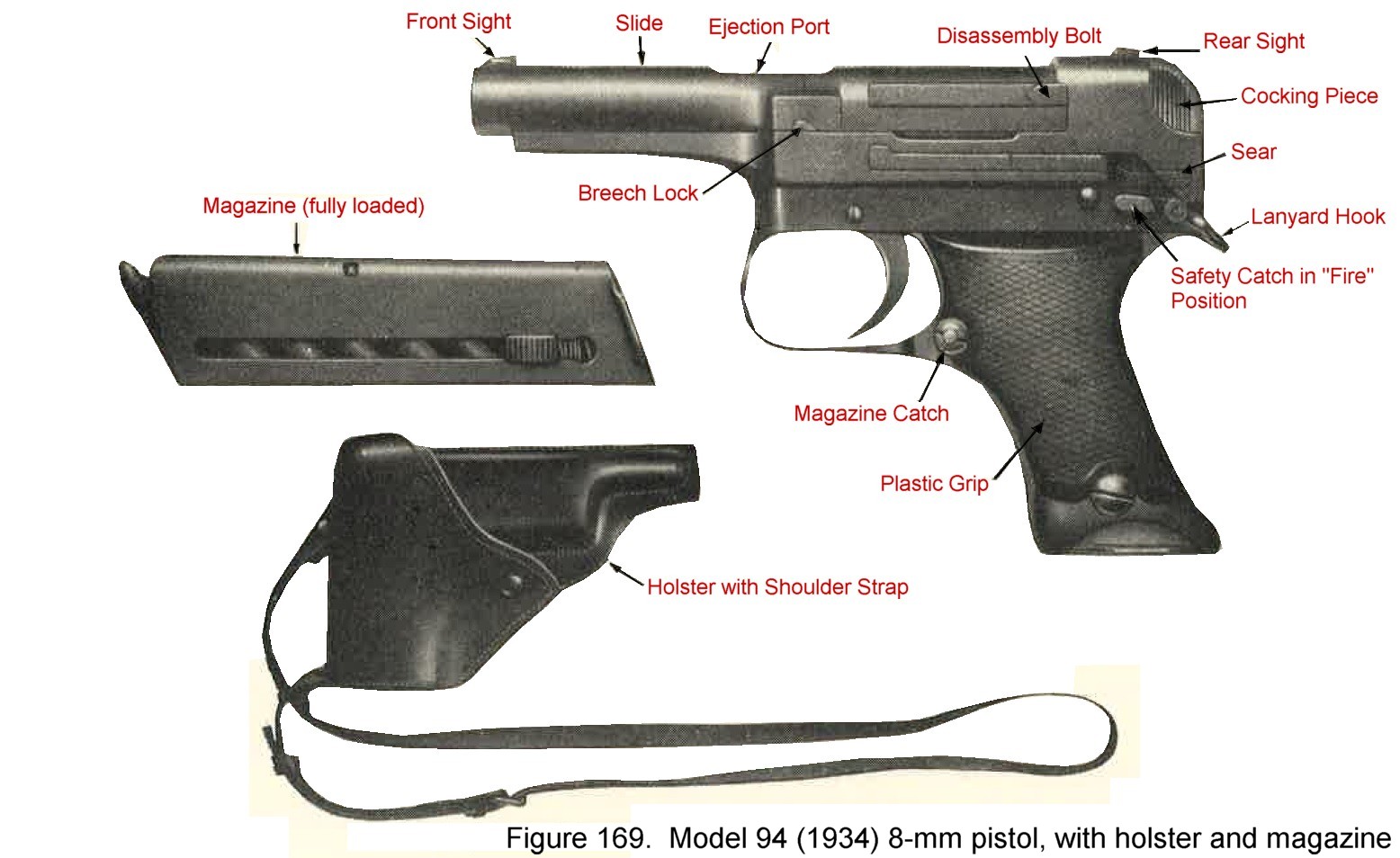
d. Model 94 (1934) 8-mm pistol.
(1) General descriptions. The Model 94 (1934) 8-mm pictol (figure 169) is the latest design of semiautomatic pistol manufactured by the Japanese. It is believed to be inferior to the Nambu and the Model 14 pistols because of poor design and manufacture. It is a semiautomatic, recoil-operated, magazine fed had weapon. Markings
 on the left side of the receiver read "Model 94". The front sight is a
blade type sight and the rear sight is non-adjustable open V notch type. A safety catch on the left rear of the receiver is moved upwards for
"safe" and downwards for "fire".
on the left side of the receiver read "Model 94". The front sight is a
blade type sight and the rear sight is non-adjustable open V notch type. A safety catch on the left rear of the receiver is moved upwards for
"safe" and downwards for "fire".
(2) Characteristics.
(3) ammunition. Rimless ball cartridges are provided and are interchangeable in the Nambu and the Model 14 pistols. 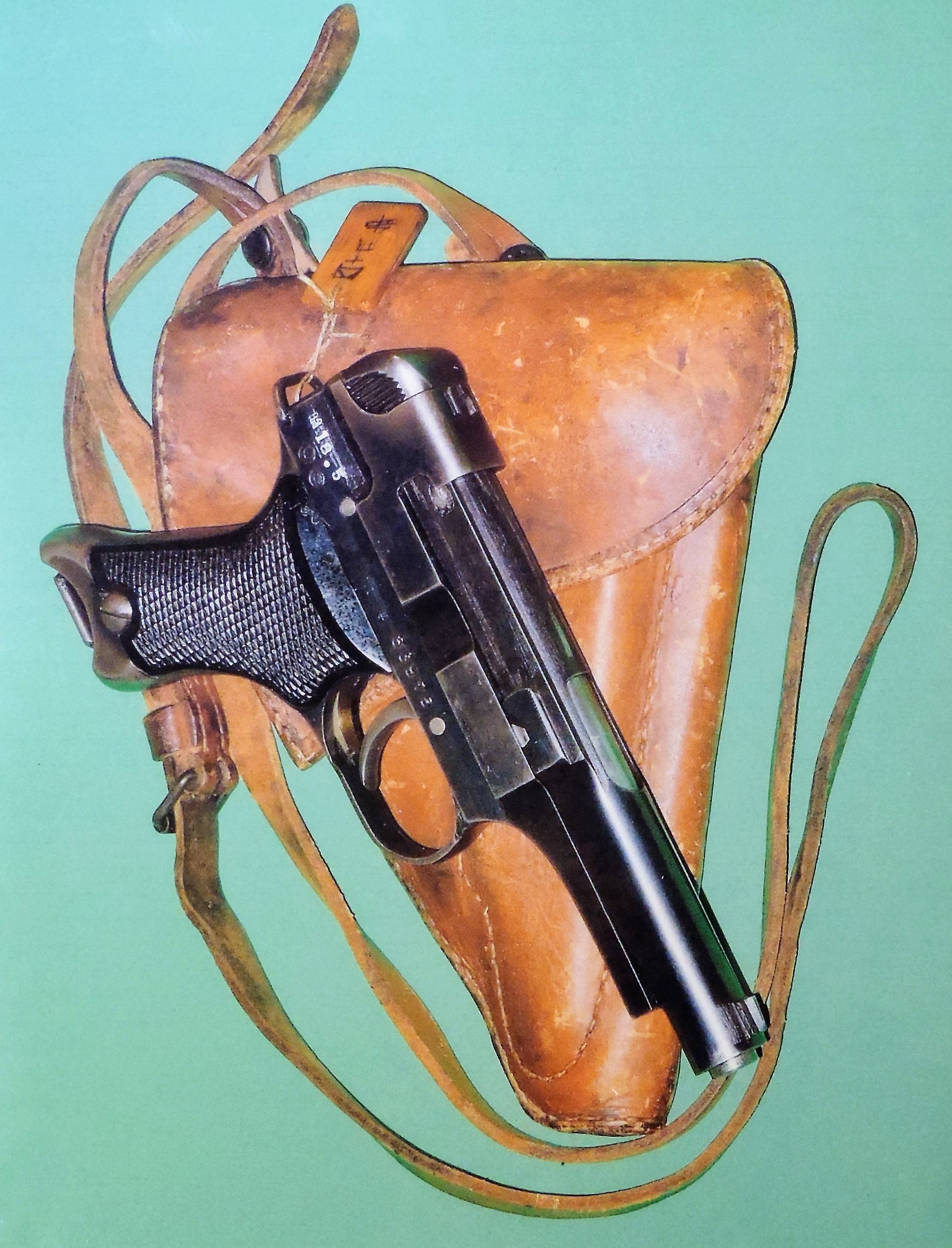
Figure 169-a. Type 94 pistol (May 1943) with holster. |
 |
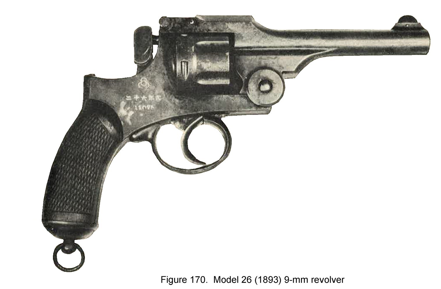
e. Model 26 (1893).
(1) General description.
This revolver is solely a double action weapon with a cylinder having six chambers (figure 170). It is a copy of the old Smith & Wesson top-break type. The weapon is equipped with blade type front sight and notch type rear sight. There is no positive safety device and owing the extremely heavy trigger pull it has a comparatiely low rate of fire. Moreover crude construction prohibits positive alignment of barrel and cylinder making its accuracy questionable. The markings
 on the right side of the frame read "26th year model".
(2) Characteristics.
(3) ammunition. This weapon fires 9-mm rimmed ball ammunition. 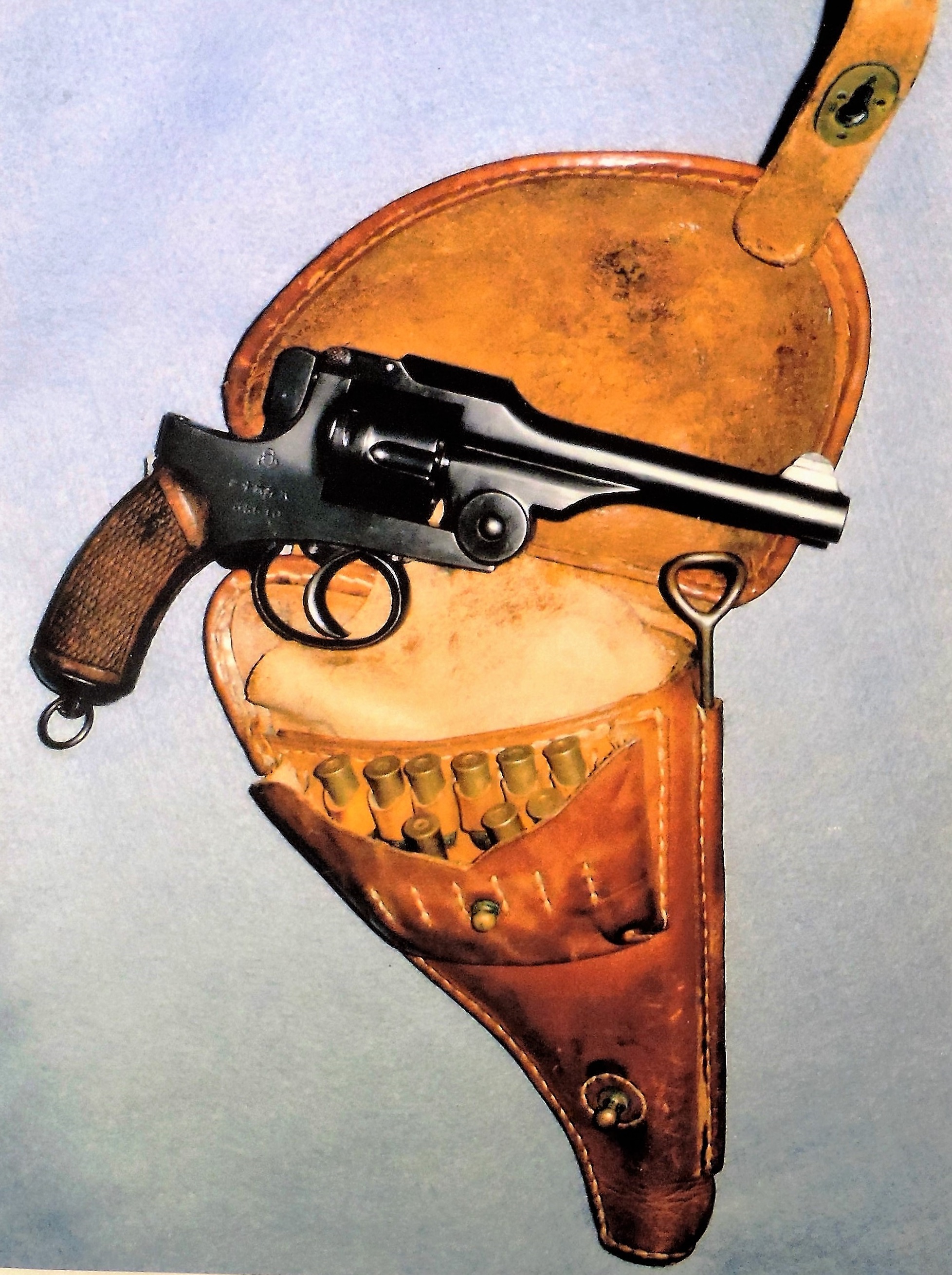
Figure 170-a. Type 26 revolver with holster, ammo and cleaning rod. |
 |
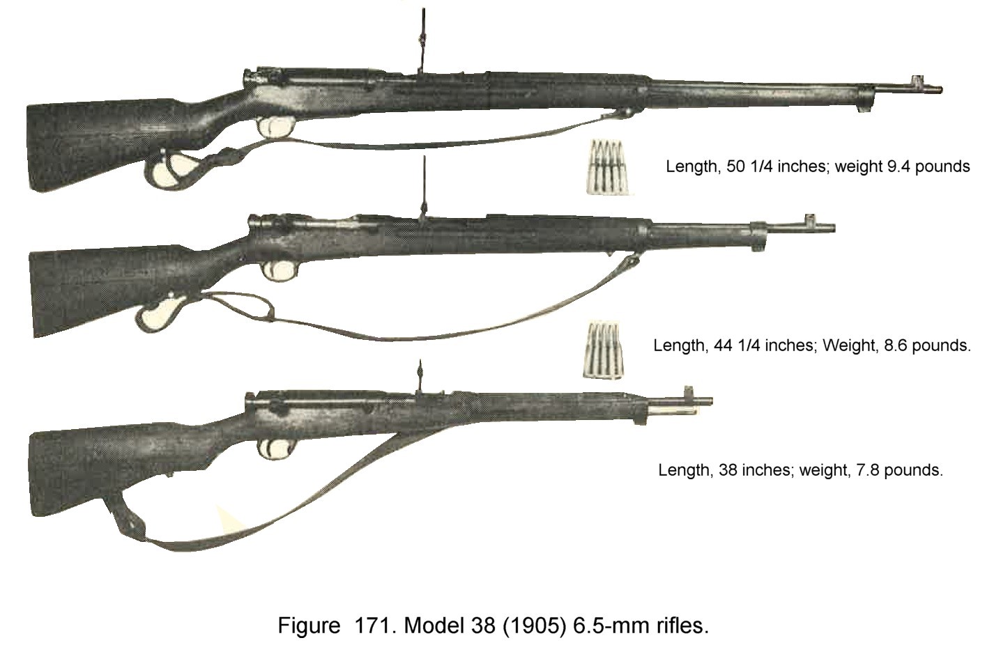
f. Model 38 (1905) 6.5-mm rifle.
(1) General descriptions. Model
This rifle is manually operated, clip loaded, magazine fed weapon, with the Mauser type bolt action which is found in most military rifles. It is commonly referred to as the Arisaka rifle. The rifle is manufactured in three standard lengths as shown in figure 171; The longest of which is the standard infantry weapon. The shorter rifles are issued to other arms. The "safety" is locked by pressing the knob at the end of the bolt and turning it to the right.
It has a blade type front sight and a leaf rear sight graduated from 100 to 2,400 meters. The small caliber, long barrel, and medium muzzle velocity
of this piece results in relatively no recoil and comparatively little muzzle flash. The markings  on top of the receiver read "Model 38".
(2) Characteristics.
(3) ammunition. The cartridges are semirimmed. Ball ammunition and tracer ammunition have been recovered. |
 |
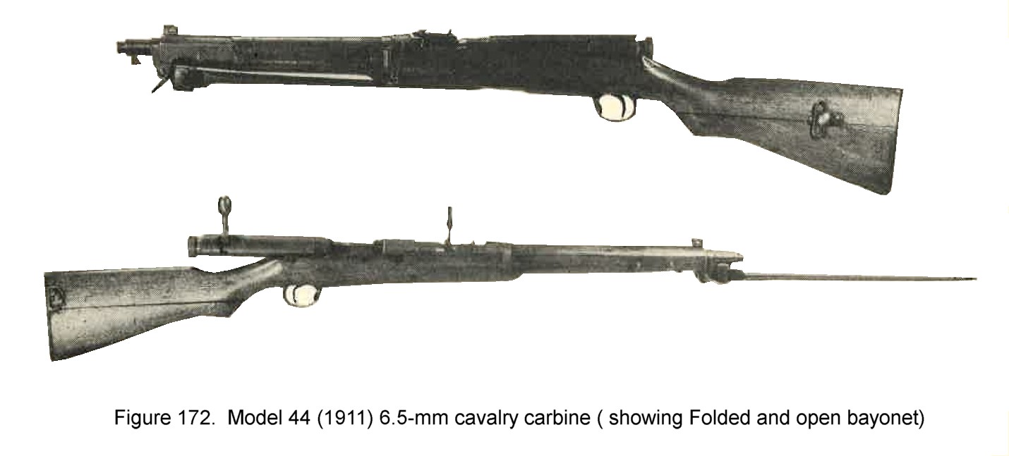
(1) General descriptions.
his carbine (figure 172) is substantially the same as Model 38 (1905) short rifle. The action, operation, and sights are similar in all Arisaka rifles. This model, howeber, has a permanently attached spike type bayonet, that folds under and rests in a slot in the stock while being carried.
This rifle has a blade front sight a a leaf rear sight graduated from 300 to 2,000 meters. There is no windage or drift adjustment.
(2) Characteristics.
(3) ammunition. The weapon uses the same ammunition as the Model 38 rifle, and the cartridges are semirimmed. Both ball and tracer ammunition have been recovered. |
 |
h. Model 99 (1939) 7.7-mm rifle.
(1) General descriptions. The Japanese replaced the 6.5-mm with this shorter, heavier caliber weapon (Figure 173). This rifle is an improved version of the Model 38 (1905) Arisaka rifle. The rifle has a blade front sight and a leaf rear sight graduated from 300 to 1,500 meters. Modifications other than the larger caliber which also helped identify this piece, are as follows:
|
- Monopod under fore end. - Antiaircraft sights arms attached to rear sight leaf. - Magazine floor plate hinged to forward part of trigger guard. - Sling swivels attached to side instead of under part of rifle. The markings 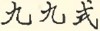 on the top of the receiver read "Model 90". Reports have
been received that a short model (38 inches overall) is being issued to service troops. on the top of the receiver read "Model 90". Reports have
been received that a short model (38 inches overall) is being issued to service troops.
(2) Characteristics.
|
 |
(3) ammunition. This is supplied in 5 round clips, 3 clips to a package. It is a rimless type supplied in ball, tracer, and armor piercing varieties, and has standard markings. This ammunition can be used in 7.7-mm Model 92 (1932) machine gun , but Model 92 ammunition is semirimmed and cannot be used in the rifle.
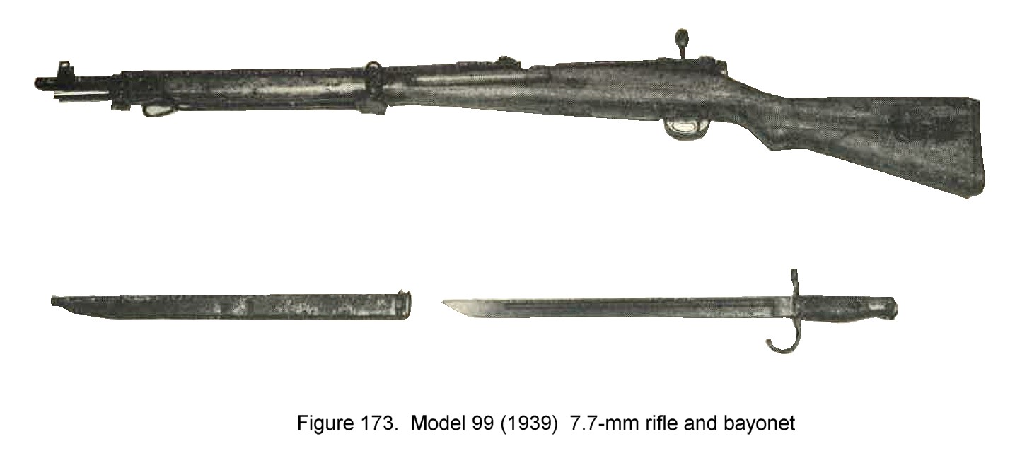
i. WWII Japanese Sniper's rifle.
(1) General description. This particular piece of equipment is found in two models, Model 97 (1937) 6.5-mm and Model 99 (1939) 7.7-mm (figure 174). The two rifles are the same length as the long Model 38 (1905) 6.5-mm and can be identified by the fact that, in addition to standard sights, the sniper's model has a telescope mounted on the left of the receiver, a turned down bolt handle, and a monopod under fore end.
|
It is believed that these rifles are manufactured more carefully than the standard rifles.
(2) Rifle Characteristics.
(2) Telescope Sight Characteristics.
|
|
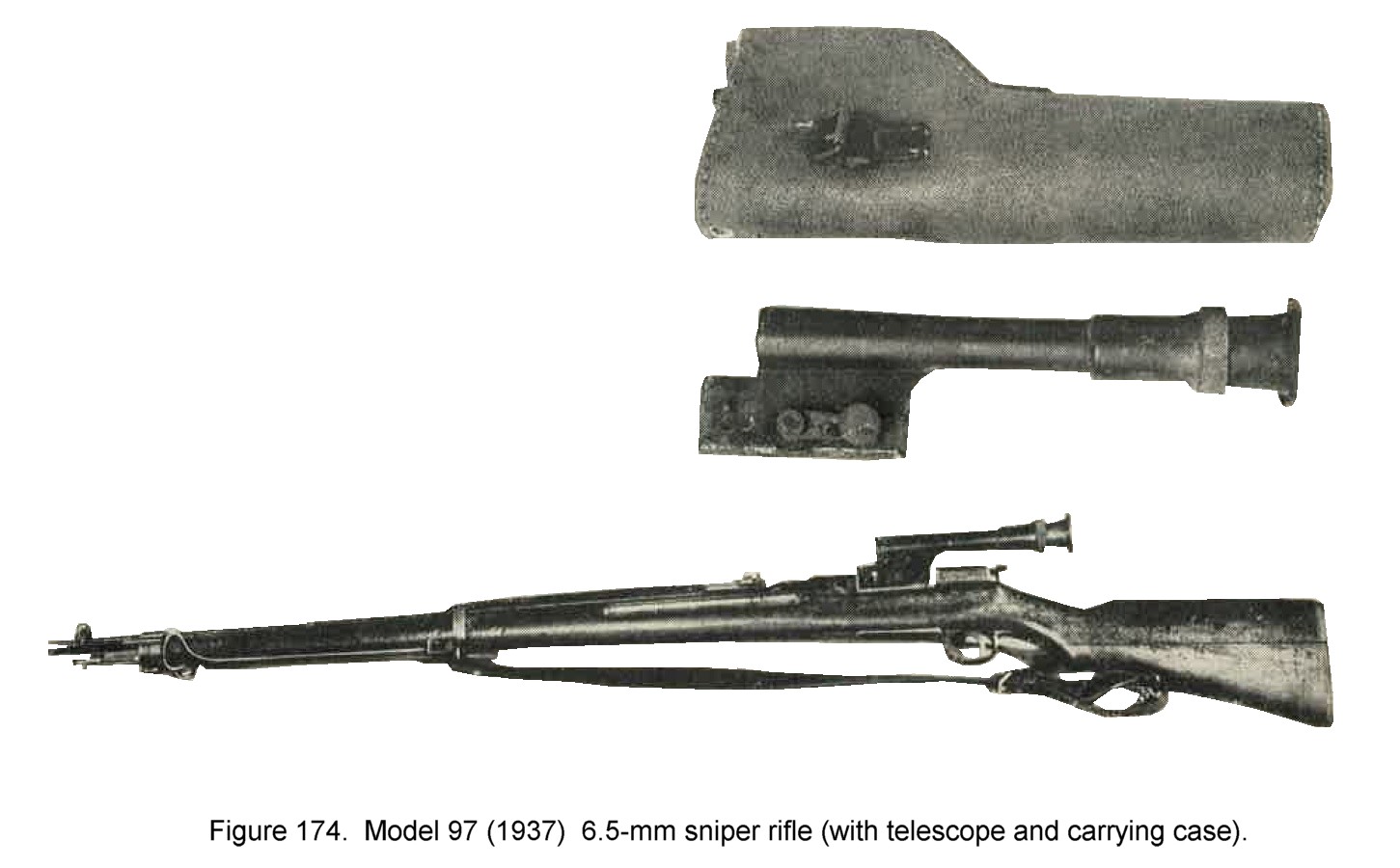
j. Rifle grenade launchers (dischargers)
(a) Fragmentation grenade Model 91 (1931). This grenade has been adopted for use as a rifle grenade by replacing the propellant charge normally found screwed into the base of this grenade, with a fin assembly. Prior to firing, the safety pin must be removed from the fuze. When projected, the fuze action will be started by the shock of the explosion upon the base of the grenade. Grenade will detonate in 7-8 seconds (approx.) after firing.
(b) Rifle smoke grenade. The rifle smoke grenade weighs 1.3 pounds and is painted silver. It contains approximately 0.6 pounds of an HC White smoke mixture. No fuze is used, the action being started by the flash of the propelling charge.
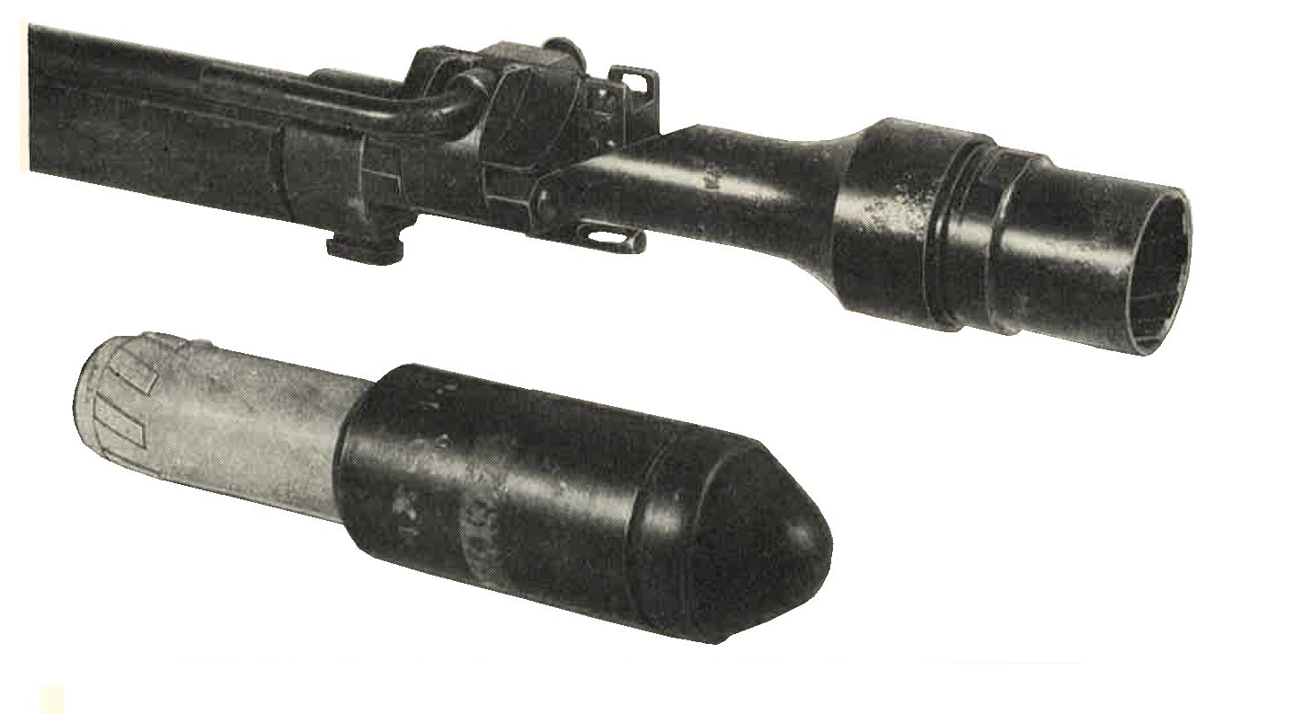
Figure 176. Rifled-type grenade launcher with armor piercing (hollow charge) rifle grenade. |
(2) Rifled type launcher. This launcher (fig. 176) is designed for projecting the hollow charge high explosive AP grenade. When fired, the action of the discharger cup rifling on the lugs (prerifiled rotating band) of the grenade forces the projectile to rotate, giving stability in flight. It is reported that this grenade is projected by a special cartridge fitted with a wooden bullet. |
| (3) Cup type launcher Model 100. This launcher is used for projecting the Model 99 (1939) fragmentation grenade. The launcher is attached to the muzzle of the rifle, and the grenade, with safety pin removed, placed inside the cup. Standard ball ammunition is used for projecting the grenade, which has a range of approximately 100 yards when using any standard Japanese rifle. The grenade time fuze is started when the weapon is fired, detonating in approximately 4-5 seconds. |
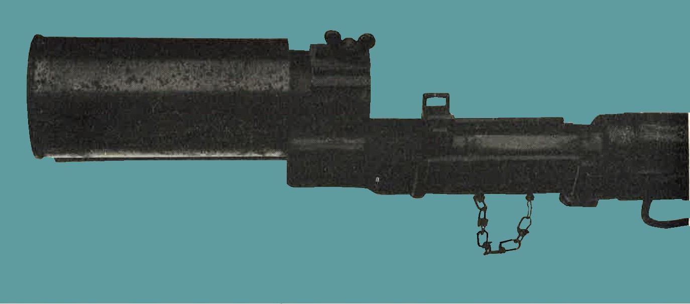
Figure 177. Cup type launcher Model 100 fitted on muzzle of rifle. |
2. WWII JAPANESE MACHINE GUNS.
a. (1) The basic machine gun is the "Nambu", Model 11 (1922) 6.5-mm light machine gun, which is a modification of the French Hotchkiss. Other types that have been directly copied are the Lewis, the Vickers, and in one instance the Oerlikon. These weapons will be foundlisted in the following sections. A matter of note is that Japanese machine guns generally do not employ slow initial extraction and therefore stoppages are frequent. The Japanese, in order to overcome this, have employed various methods of oiling ammunition either by automatic or gravity oilers, built directly onto the weapon, or oiling ammunition before loading into box magazines. To complicate the ammunition picture even further, they have indicated that their 6.5-mm machine guns normally use a reduced charge, possibly to overcome stoppage and to avoid pre-oiling. Also their 7.7-mm light and heavy machine guns are built to use either a rimmed, semirimmed or rimless ammunition, which, with one exemption noted in the following pages, is not interchangeable.
(2) Submachine guns. No submachine gun of Japanese manufacture, comparable to the Thompson, M3 or Reising has been found, although several German Solothurn 7.63-mm (.30 cal) and 9-mm (.35 cal) SMGs and Schmeisser MP 28, SMGs have been recovered.
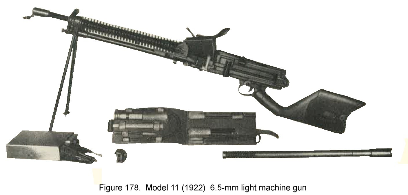
b. Model 11 (1922) 6.5-mm light machine gun.
(1) General description. This is a gas operated, air cooled, machine gun with hopper feed which holds 6 - 5 round clips of ammunition (figure 178). Positive identification can be made from the following markings which appear on the top of the receiver
 and read "11th year model". It is equipped with a blade front-sight and a V notched rear leaf-sight sliding on a ramp. There is no
windage or drift adjustment. The safety lever (See figure 178) is turned down to a vertical position to make the weapon safe.
and read "11th year model". It is equipped with a blade front-sight and a V notched rear leaf-sight sliding on a ramp. There is no
windage or drift adjustment. The safety lever (See figure 178) is turned down to a vertical position to make the weapon safe.
(2) Characteristics.
(3) Ammunition. Clips of 5 rounds standard or reduced charge 6.5-mm ball rifle ammunition are used. |
 |
c. Model 96 (1936). 6.5-mm light machine gun.
(1) General description. This is a gas operated, magazine fed, air cooled, fully automatic light machine gun (figure 179). Its appearance is somewhat similar to that of the British Bren. The markings
 read
"Model 96" and are stamped on the top of the receiver. This weapon has a blade front sight and a leaf rear sight controlled by
a "click" drum. The graduations are from 200 to 1,500 meters and there is a windage adjustment.
read
"Model 96" and are stamped on the top of the receiver. This weapon has a blade front sight and a leaf rear sight controlled by
a "click" drum. The graduations are from 200 to 1,500 meters and there is a windage adjustment.
|
There is also a telescopic sight
with a 10 degree field of view and a 2 1/2 x magnification. A safety lever is located on the left side of the trigger housing and
is set at horizontal to "fire", and vertical for "safe".
(2) Characteristics.
(3) Ammunition. 6.5-mm semirimmed cartridges in boxes marked  are provided for this weapon. These
have the same dimensions as the standard 6.5-mm cartridge although the Japanese have indicated that these have a reduced
propelling charge. The regular rifle ammunition may cause stoppages, but can safely be used. are provided for this weapon. These
have the same dimensions as the standard 6.5-mm cartridge although the Japanese have indicated that these have a reduced
propelling charge. The regular rifle ammunition may cause stoppages, but can safely be used.
|
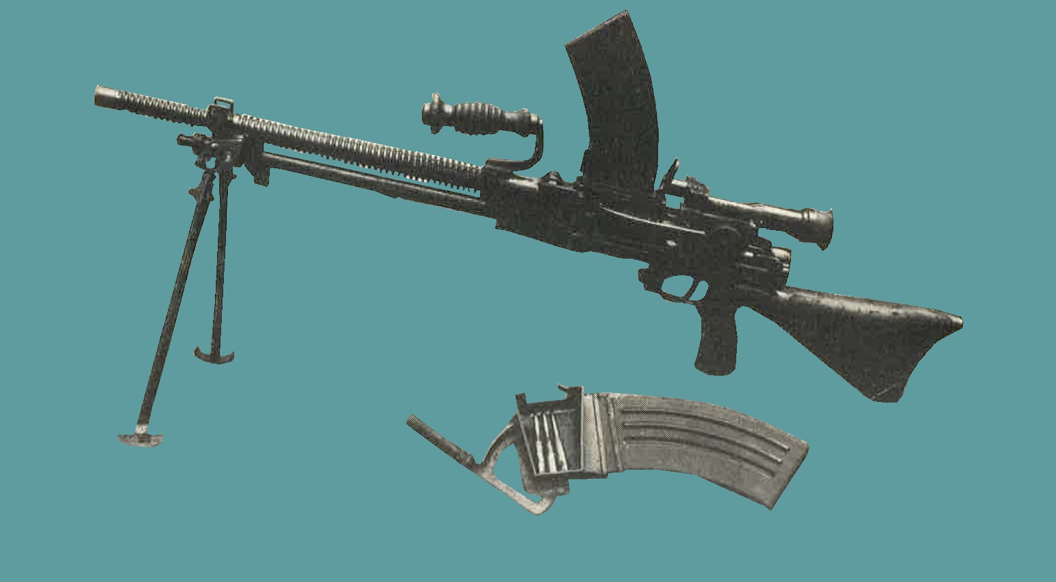
Figure 179. Model 96 (1936) 6.5-mm light machine gun (showing magazine, magazine filler and telescopic sight). |
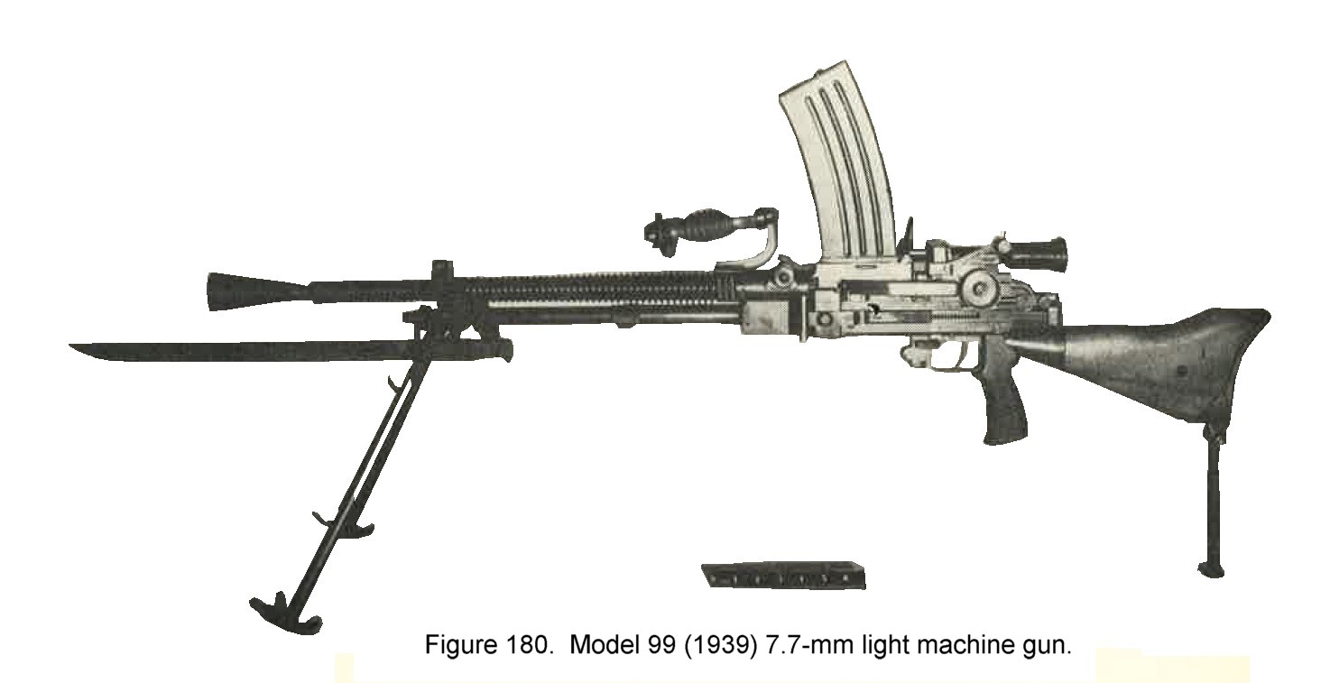
d. Model 99 (1939) 7.7-mm light machine gun.
(1) General description. This is a gas operated, magazine fed, air cooled, light machine gun (figure 180). Its appearance is almost identical to the Model 96 with two exceptions, that it has an adjustable rear monopod and a barrel locking nut instead of a barrel catch. It can further be identified by the markings on teh top of the receiver
 meaning "99 Model". It has a blade front sight and a rear peep sight controlled by a "click" drum graduated from 200 to 1,500
meters. There is a windage adjustment. A telescopic sight 10 degrees field of view and 2 1/2 x magnification is also provided.
The safety lever on the right side of the trigger housing is set at horizontal to "fire", and vertical for "safe".
meaning "99 Model". It has a blade front sight and a rear peep sight controlled by a "click" drum graduated from 200 to 1,500
meters. There is a windage adjustment. A telescopic sight 10 degrees field of view and 2 1/2 x magnification is also provided.
The safety lever on the right side of the trigger housing is set at horizontal to "fire", and vertical for "safe".
(2) Characteristics.
(3) Ammunition. The weapon uses 7.7-mm rimless ammunition only. This ammunition can be used in Model 92 heavy machine gun, but the semirimmed ammunition for Model 92 cannot be used in this gun. |
 |
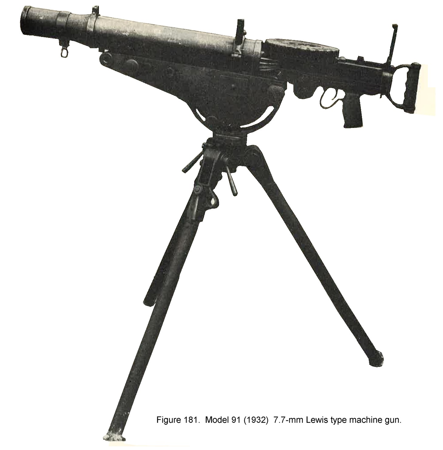
e. Model 92 (1932) 7.7-mm Lewis type MG.
(1) General description. This weapon is an air cooled, gas operated, drum-fed, full automatic gun. (See figure 181). With the exception that the cocking handle is on the left and that there is no provision allowing it to be changed to the right side of the gun, if so desired, this weapon is a duplicate of the British Lewis. It can be easily recognized by its similarity to the latter weapon.
The markings  meaning "92 Model" are stamped on the receiver. Without
removing the gun from its mount, the main portion of the tripod head can be moved from a horizontal to a vertical position,
marking a satisfactory AA mount. This can be done in approximately 15 seconds. meaning "92 Model" are stamped on the receiver. Without
removing the gun from its mount, the main portion of the tripod head can be moved from a horizontal to a vertical position,
marking a satisfactory AA mount. This can be done in approximately 15 seconds.
(2) Characteristics.
(3) Ammunition, 7.7.rimmed ammunition, Japanese copy of the British .303 in. ball ammunition. |
 |
f. Model 92 (1932) 7.7-mm heavy machine gun.
(1) General description. This is the standard Japanese heavy machine gun. It is a gas operated, strip-fed, full automatic, air-cooled, modified Hotchkiss type weapon (figure 182).
Its forerunner, which may still be in use as of 1944, was the Model 3 (1914) which fired 6.5-mm ammunition. Markings which appear on the receiver
read "92 Model". The standard sights consist of
a blade front sight and a rear peep sight mounted on a post adjustable for windage and range (300 to 2,700 meters).
Special antiaircraft front and rear sights are provided, and there are 3 variations of optical rear sights which are often
used. The weapon is set on safety by turning the trigger thumb piece.
(2) Characteristics.
(3) Ammunition. This gun uses 7.7-mm semirimmed ammunition (Ball tracer, AP and incendiary). It can also use the 7.7 rimless ammunition if loaded on strips. |
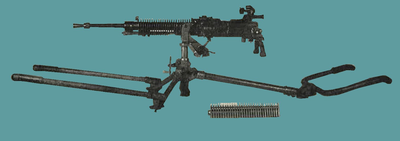
Figure 182. Model 92 (1932) 7.7-mm heavy machine gun - showing carrying handles and ammunition strip. |
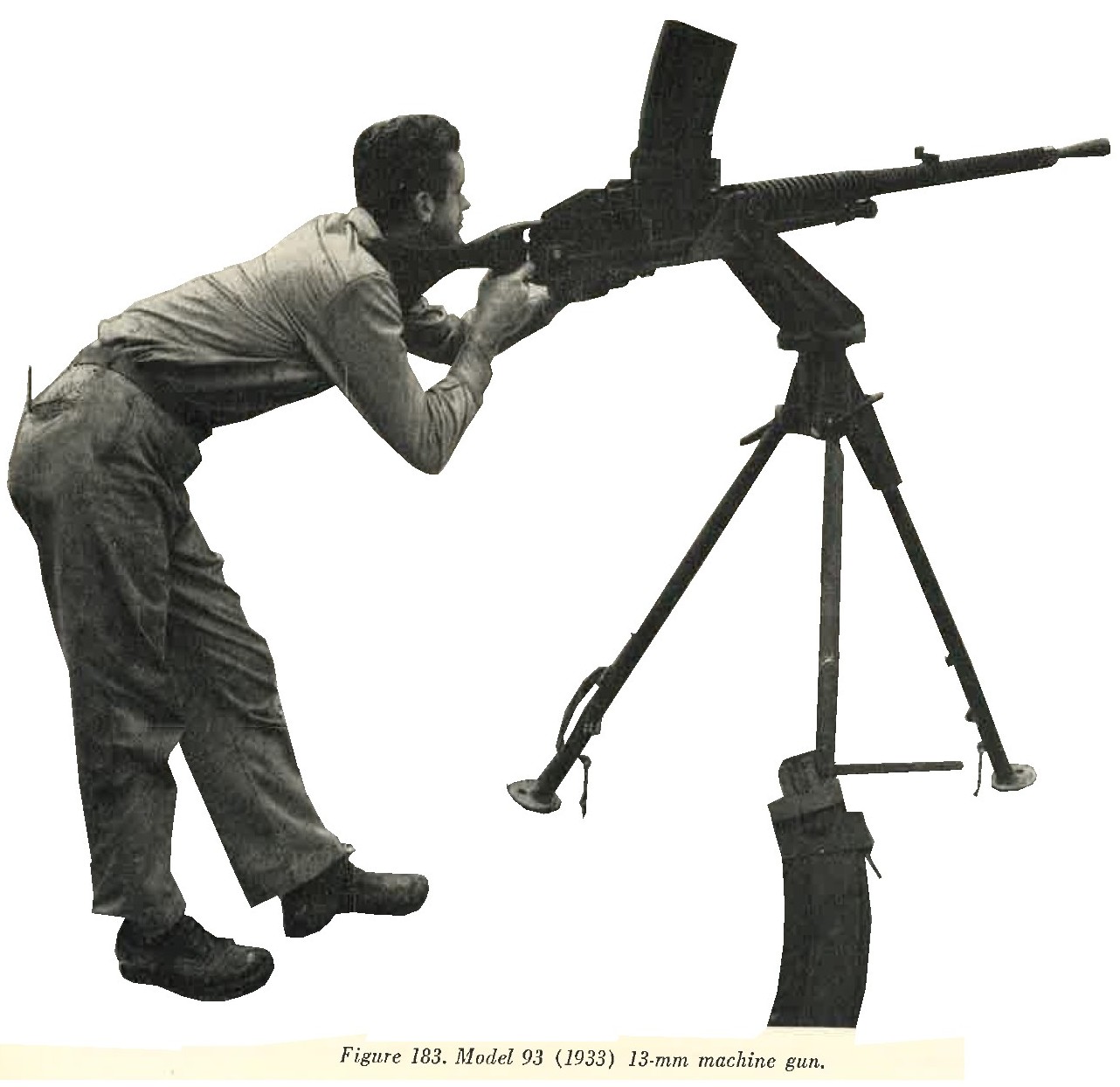
g. Model 93 (1933) 13-mm machine gun.
(1) General description. This is a gas operated, air cooled, magazine fed, full automatic, Hotchkiss type weapon (figure 183). While it is primarily an antiaircraft gun, it can be used for ground purposes. This weapon has been found in single and twin mounts (See Sec. III, par. 3). The markings
 meaning "93 Model" appear on the receiver. The antiaircaft sights on dual mounts are of the calculating type
graduated for ranges from 200 to 3,000 meters, with provision for corrections based on plane speeds varying up
to 500 kilometers per hour. For ground use there is a blade front sight and a leaf rear sight graduated from
200 to 3,600 meters.
meaning "93 Model" appear on the receiver. The antiaircaft sights on dual mounts are of the calculating type
graduated for ranges from 200 to 3,000 meters, with provision for corrections based on plane speeds varying up
to 500 kilometers per hour. For ground use there is a blade front sight and a leaf rear sight graduated from
200 to 3,600 meters.
(3) Ammunition. Ball, armor piercing, and tracer cartridges are provided. |
 |
3. WWII JAPANESE MORTARS AND GRENADE DISCHARGERS.
a. General. Although all know types of both mortars and grenade dischargers are dealt with here, there are indications that the Japanese Army has mortars heavier than 90-mm and at least up to 150-mm.
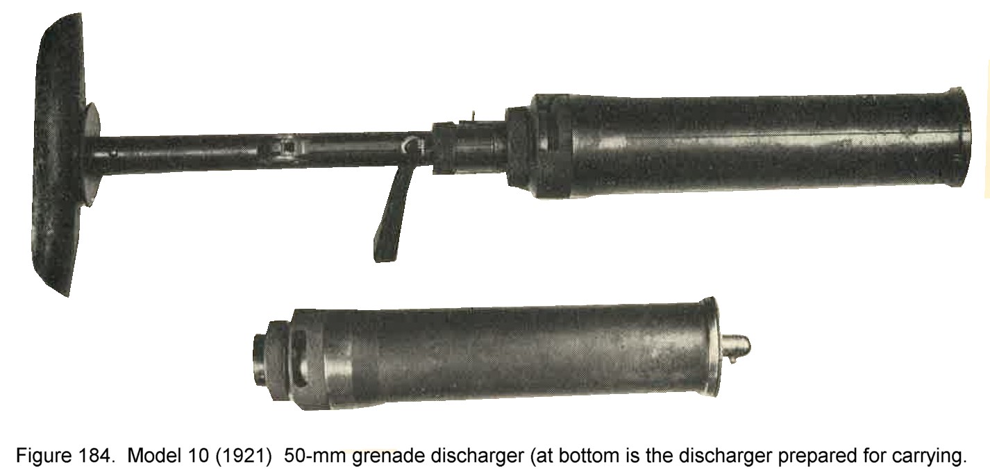
b. Model 10 (1921) 50-mm grenade discharger.
(1) General description. This is a smooth bore, muzzle loaded weapon (figure 184). It has the special feature of a rnage control device in the form of a graduated thimble by which a gas port at the base of the tube can be varied in size. For shorter ranges, part of the propellant gases escape to the side. It is believed that this weapon is used primarily for discharging flares and that the heavier Model 89 grenade discharger is used for firing high explosive and other projectiles.
(2) Characteristics.
(3) Operation. There is no safety device on this weapon. To operate, first remove the safety pin from projectile. The grenade or signal projectile is placed in the barrel. The weapon is fired by a trigger attached to the pedestal. |
 |
(4) Ammunition. This weapon fires: - Model 91 grenade,
- Model 11 smoke shell,
- Model 10 flare shell,
- Model 10 signal shell,
- Model 91 pyrotechnic grenade,
- Model 10 blank.
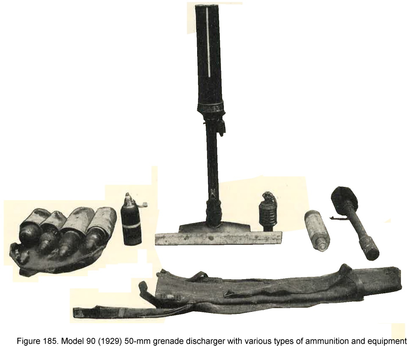
C. Model 89 (1929) 50-mm grenade discharger.
(1) General description. This is a muzzle fed, rifled weapon which is widely used in the Japanese Army (figure 185). The standard projectile is a high explosive shell which contains the propellant charge in its base. Ranges are controlled by rotation of the knurled range knob. Rotation of the projectile is obtained because the rotating band is expanded against the rifling when the weapon is fired. The weapon is trigger fired. A recent modification of the discharger is fitted with a device to indicate the correct firing angle (45 degrees).
There are two range scales. One gives the ranges (120 to 670 meters) governing the use of the Model 89 HE shell and the other (50 to 170 meters) is used for firing Model 91 grenade.
(2) Characteristics.
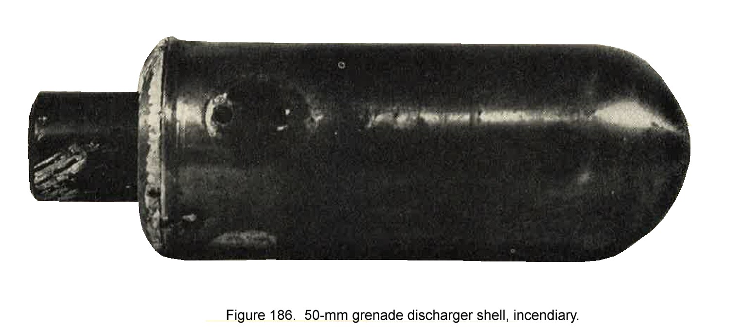
(3) Ammunition. The following types of ammunition are known to be provided; - Model 89 high explosive shell. - Model 91 grenade. - Smoke shell - Model 94 practice shell - Pyrotechnic signals (described in chapter 10) - and incendiary (figure 186). |
 |
|
The incendiary shell has a light metal body and weighs approximately 1.25 pounds. It contains about 0.7 pouns of incendiary mixture. The smoke shell weighs approximately 2 pounds, contains about 4 ounces of HC type smoke mixture. The body has the same shape as the high explosive shell, but may be distinguiushed by having two white bands on the body. |
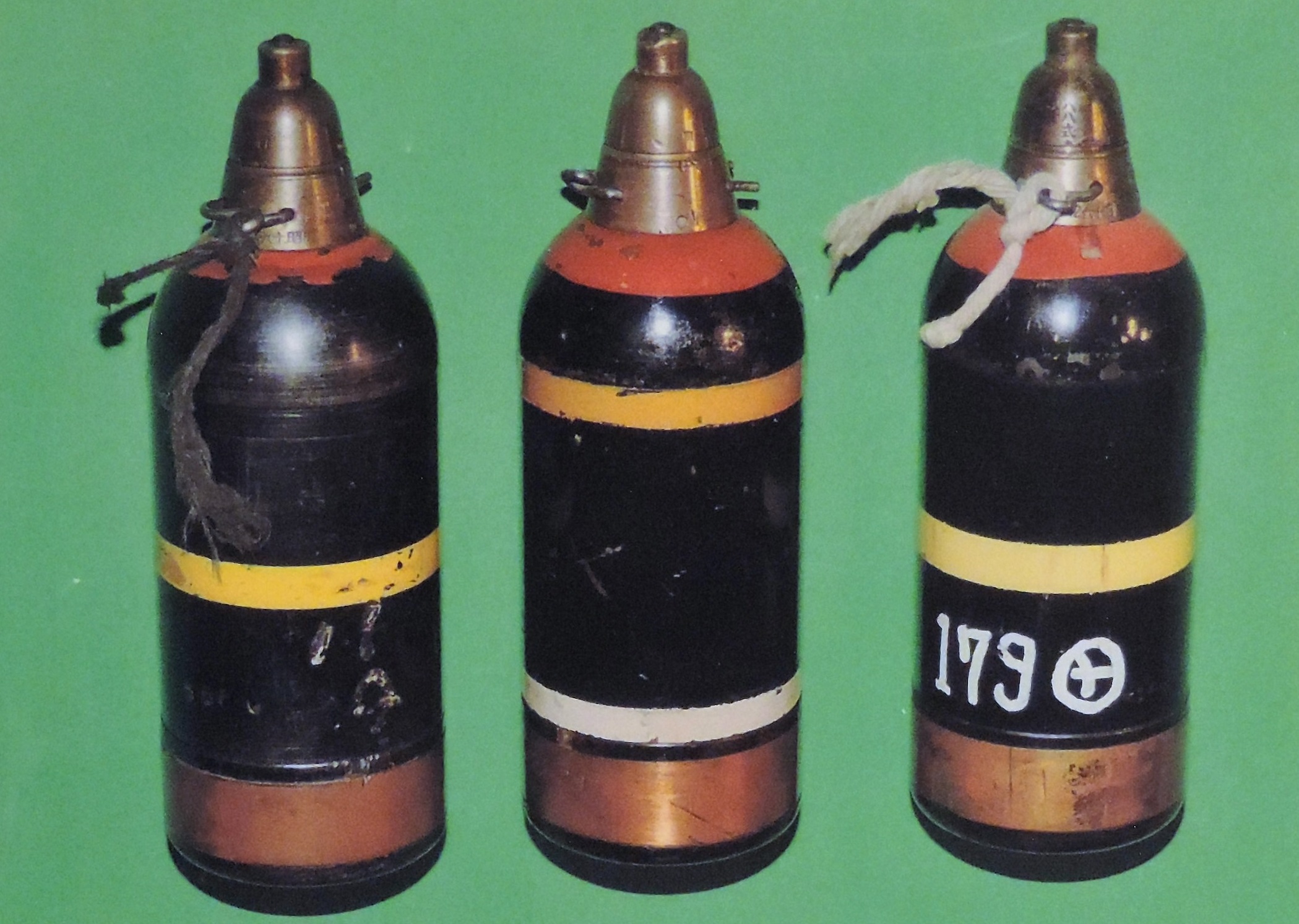
Figure 185-a. WWII Japanese High Explosive knee mortar rounds.
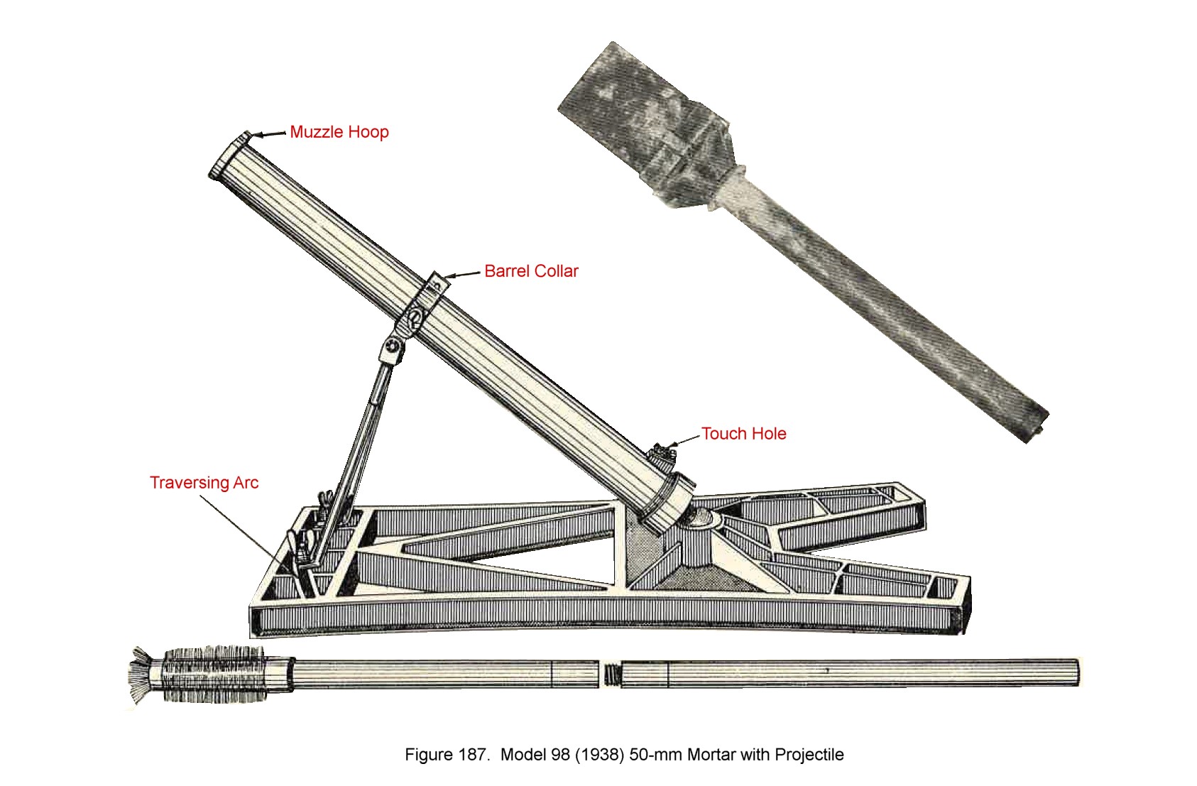
d. Model 98 (1938) 50-mm mortar.
(1) General description. This is a smooth bore muzzle loaded weapon with fixed elevation of approximately 40 degrees and limited traverse (figure 187). It is fired by a lanyard attached to a friction primer affixed to the base of the tube. A special feature is a range slide which may be clamped to the muzzle. This regulates the length of the stick (spigot) extending into the barrel. The greater the distance the stick extends into the barrel, the greater the range.
(2) Characteristics.
(3) Ammunition. The weapon fires a stick bomb weighing approximately 10 pounds and containing 7 pounds of picric acid in blocks. A smaller bomb containing 5 pounds of picric is also used. A finned bangalore torpedo may also be fired. No other ammunition has been recovered to date (1944). |
 |
e. Model 11 (1922) 70-mm mortar.
(1) General description. This is an obsolescebt muzzle loaded, rifle-bore weapon (figure 188). The barrel is supported by a single elevating screw. The markings on the breech end of the barrel
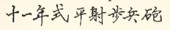 read "11th year model high
angle infantry gun". The latch pin on the breech end of the barrel must be set in to release the safety device. The weapon is fired
by means of a lanyard attached to the striker arm.
read "11th year model high
angle infantry gun". The latch pin on the breech end of the barrel must be set in to release the safety device. The weapon is fired
by means of a lanyard attached to the striker arm.
(2) Characteristics.
(3) Ammunition. The high explosive shell has the propellant powder in its base and operates in the same manner as the Model 89 grenade discharger shell prevously described. |
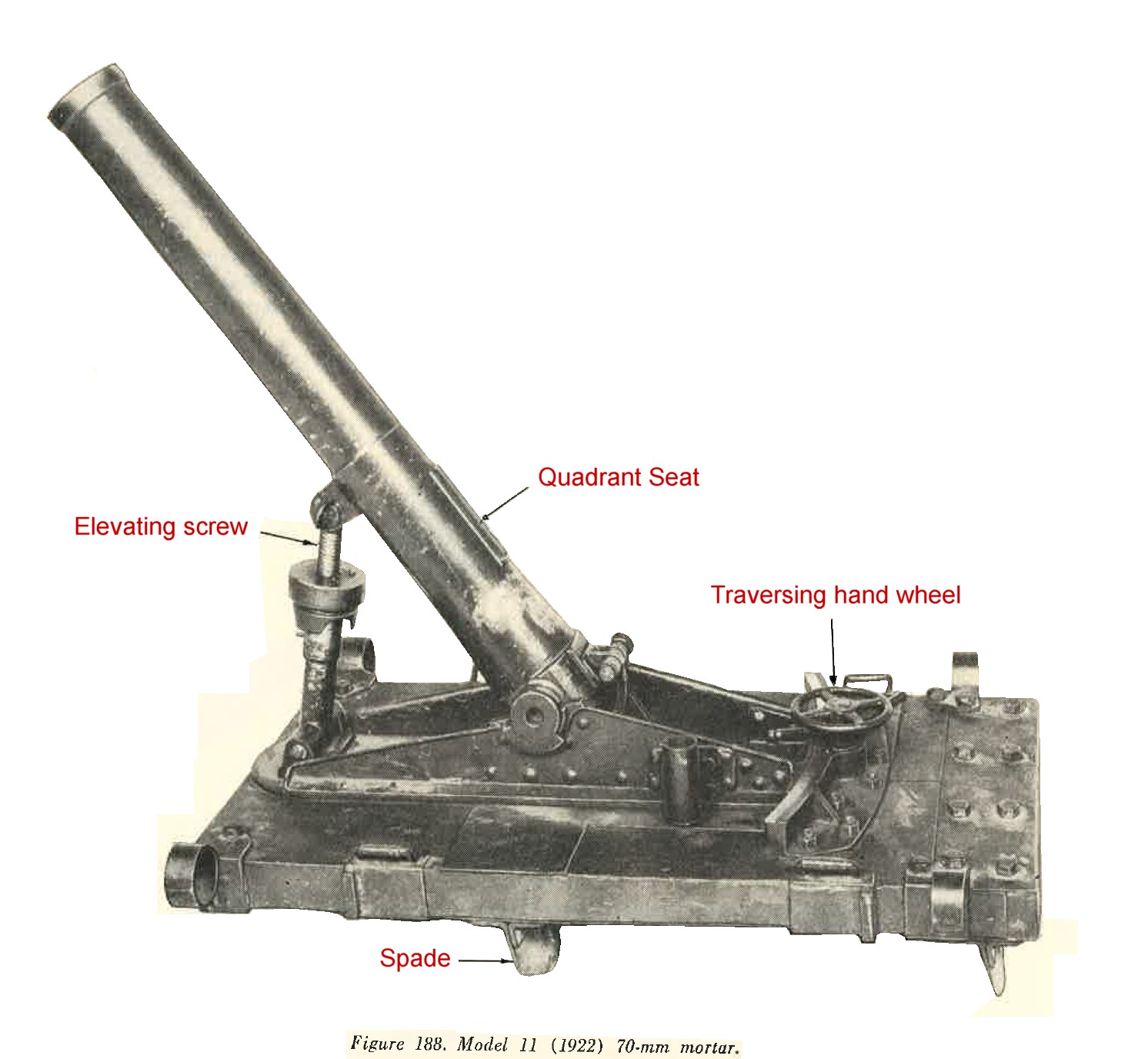 |
f. 70-mm barrage mortar.
This is a smooth bore, muzzle loaded weapon of a very simple comstruction (figure 189). It fires a shell probably designed for use against low flying aircraft (figure 189), or firing over the heads of ground troops. When fired, the projectile reaches a range of 3,000 to 4,000 feet when it expels a parachute-supported high explosive charges 11/16 inch in diameter and 3 inches long which in turn explode in the air. If an unexploded shell be found on the ground, it should be marked "Dangerous" and left for disposal by trained personnel.
 |
 |
g. Model 97 (1937) 81-mm mortar.
(1) General description. This weapon is very similar to United States 81-mm mortar M1. It is a smooth bore, muzzle loading, high angle fire weapon (figure 191) which breaks down into 3 sections for transport. The markings
 which appear on the base
of the barrel read "97 model small trench mortar". The mortar is provided with a collimator sight which is heavier and more complex than the
U.S. M1 sight.
which appear on the base
of the barrel read "97 model small trench mortar". The mortar is provided with a collimator sight which is heavier and more complex than the
U.S. M1 sight.
(2) Characteristics.
|
 |
(3) Ammunition. This weapon fires high explosive shells which are interchangable with the United States M43 81-mm light shell. Heavier shells have been reported but no specimens have been recovered. The fuzes can be adjusted to give instanteneous or delay action detonations.
h. Model 98 (1939) 81-mm mortar.
(1) General description. Model 99 is similar to Model 97 except that it has a much shorter barrel and is equipped for trigger firing with a mechanism at base of the barrel (figure 192). For transport, this mortar breaks down into three sections, each weighing approximately 17 pounds. It may be fired with United States M43 81-mm mortar shells, in which case a maximum range of 2,500 yards may be obtained.
(2) Characteristics.
|
 |
(3) Ammunition. HE and smoke or chemical shells have been recovered. The fuse may be adjusted for instantaneous or delay detonation.
i. Model 94 (1934) 90-mm mortar.
(1) General description. This is a smooth bore, muzzle loading weapon with a fixed firing pin (figure 193). A special feature is the recoil system, consisting of two recoil cylinders on one U shaped frame with cylinders located on each side of the barrel. The japanese markings on the base of the barrel
 read "94 Model light trench mortar".
(2) Characteristics.
Figure 193-a. WWII Japanese High Explosive 90-mm mortar rounds. |
 |
(3) Ammunition. Model 94 mortar fires HE and incendiary ammunition. The incendiary shell is 16 inches long, weighs 11.5 pounds. The mixture is white phosphorus, carbon disulphide and 40 impregnated rubber pellets. This shell can be identified by a red band below the fuse, a blue band between the fuze and bourrelet, a yello wband between the bourrelt and fin, and a white band at the junction of the shell and body and the fin. The fuze may be adjusted to give either instantaneous or delayed detonation.
j. Model 93 (1933) 150-mm mortar.
(1) General description. The photograph (figure 194) shown is believd to be that of the Model 93 (1933) 150-mm mortar, a smooth bore, muzzle loaded, lanyard fired weapon.
(2) Characteristics.
|
 |
(3) Ammunition. Projected reported as weighing (total) 56 pounds and containing approximately 14 pounds of explosive.
4. WWII JAPANESE GRENADES, LAND MINES, AND BOOBY TRAPS.
a. General. The following section provide a general picture of Japanese grenades and land mines. Certain of these items have been used in the construction of booby traps. The most common methods of making booby traps are covered here, However, there may have been other methods for manufacturing them.
b. Booby traps. Although the Japanese use of booby traps has been limited as compared to the Germans, ir is expected that these traps will be more and more frequently encountered as Allied forces push the Japanese from prepared positions. As many types of Japanese Ammunitions are suitable for employment as booby traps only the most common are listed.
| |
The Model 23 pull type fragmentation grenade is particularly suitable for this purpose when attached to doors, window frames, and general items of
abandoned equipment. In addition multiple reports have been received of captured allied grenades (i.e. British No. 36 and United States MK 2)
being similarly employed.
Although there is no evidence to date that the stick grenade, the bangalore torpedo, or explosive canister from the barrage mortar shell have been used as booby traps, the fact that all have pulled igniters and accidents have occurred to troops handling them, prove that they are most suitable for such. The 3 types of fragmentation grenade models 91, 97 and 99 ("Kiska") grenade are equipped with percussion ignited fuses. They have been used with a suspension wire device which can be tripped. The grenade is placed bottom up inside an improvised tube this ensuring that the grenade will fall head first so as to detonate the fuse, when a wire is tripped (see figure 195). A piece of bamboo or empty cartridge case is sometimes used in lieu of a tube. |
|
Another and less elaborate variation is found in the use of the above listed grenades under foot board. The weight of the foot fires the detonator
instantenously.
many of the land mines have been used as booby traps and work on the same principle, Model 93 being equipped so that it can be activated by pressure from 7 to 200 pounds. Only one or two electrically operated booby traps have been encountered so far. they operate on a low voltage and are generally attached to equipment such as radios and vehicle ignition switches. It can be expected that booby trap fuzes of more advanced design, will probably appear in the near future, as the Japanese are driven back. 
|
 |
c. Model 91 (1931) hand grenade.
(1) General description. Model 91 (1931) fragmentation grenade (figure 196) can be thrown by hand, fired either from Models 10 or 89 grenade dischargers, or fired from a rifle grenade launcher (discharger) with tail assembly added. The base constains a primer and propelling charge for use when firing from a grenade discharger.
(2) Characteristics.
Figure 196-a. WWII Japanese Model 91-mm hand grenade (knee mortar/rifle/hand). (3) Operation. (a) To arm. With safety screw in position, screw firing pin down into firing pin holder, with screw driver or knife blade, as far as it will go. (b) To use as hand grenade. Hold grenade with fuze pointing downward, remove safety pin, making sure that safety cover does not fall off. Strike head of fuze against solid object such as helmet keeping hands clear of the gas vent hole. Throw immediately since action of fuze is sometimes erratic. (c) To use in grenade discharger. Remove safety pin and drop into discharger. |
 |
d. Model 97 (1937) hand grenade.
(1) General description. The Model 97 (1937) fragmentation hand grenade (figure 197) is carried by all front line troops and is almost identical with Model 91, except hat it has no provision for a base propellant attachment and has a shorter fuze delay time. It cannot be fired from a grenade discharger.
(2) Characteristics.
Figure 197-a. WWII Japanese Type 97 hand grenades. |
 |
(3) Operation.
(a) To arm. With safety pin in position, screw firing pin down into firing pin holder as far as it will go.
(b) To throw. Hold grenade with fuze pointing downward. Remove safety pin, being sure that safety cover does not fall off.Strike head of fuze against solid object such as helmet keeping hands clear of the gas vent hole. Throw immediately since action of fuze is sometimes erratic.
e. Model 99 (1939) hand grenade.
(1) General description. This grenade has been identified as Model 99 (figure 198). It is smaller than the Model 97 and 91 fragmentation grenades and unlike these, it has a smooth cylindrical body with a flange at either end. It may be ;aunched from a special launcher mentioned previously under Section "Rifle grenade launchers" (figures 176 and 177).
(2) Characteristics.
Figure 198-a. WWII Japanese Model 99 hand grenade. |
 |
(3) Operation.
(a) To arm. Remove safety pin which is held in place by a cord.
(b) To use as a hand grenade. Strike the head of the fuze on a hard object and throw immediately. Since the firing pin is integral with the firing pin holder no screwing or unscrewing is necessary, as with Models 91 and 97 fragmentation grenades. It can be used as a booby trap by removing the safety pin and setting under a floor board or chair.
(4) Alternative fuze. It is believed that there is a variation of this grenade knwon as the Model 99B, which is activated by a friction igniter fuze.
f. Model 23 grenade.
(1) General description. This grenade (Figure 199) appears to have been appears to have been designed to use either as a hand grenade or a booby trap. It has a pull type friction igniter fuze with a time delay reported as approximately 5 seconds. Because a pull (from 2 1/2 pounds to 5 pounds) on the fuze cord ignites the time fuze, it could easily be adapted for use as a booby trap by tying the cord to a trip wire. The lugs and rings on the side are convenient for anchoring the grenade in place when so used. It has also been found in a booby trap with a high explosive artillery shell tied to it for augmenting the power of the explosion.
(2) Characteristics.
|
Figure 199. Model 23 hand grenade. |
g. 1/2 kg. Grenade.
5.3 inches long and weighing 1.1 pounds (approximately), it may be thrown by hand or projected from the grenade discharger Model 89. Incindiary filling is White phosphorus.
h. Incendiary stick grenade.
(1) General description. The body of this grenade (figure 200) is filled with impregnated rubber pellets in a phosphorus carbon disulphide solution. There are some 40 pelletts in each grenade, which are scattered by a central busting charge. It is also possible that this grenade is sometimes filled with phosphorus smoke contents. (2) Characteristics.
| The grenade is 13.s inches long and the body has a diameter of 2.1 inches. The handle is made of wood. |
Figure 200. Incendiary stick hand grenade. |
(2) Operation.
(a) To arm. Make sure that the safety pin is in position and that the firing pin is threaded down into the firing pin holder.
(b) To throw. With the fuze pointnig downward. Withdraw the safety pin. Making sure that the safety cover does not fall off, strike the head of the fuze against some hard object, such as the heel of your shoe or the top of your helmet. There should be no delay in throwing the grenade, since actual fuze delay time is not known.
i. High explosive stick hand grenade.
(1) General description. This is the well known "potato masher" type of grenade with a pressed metal cap at the end of the handle (figure 201). It has a smooth cylindrical body.
(2) Characteristics.
|
Figure 201. WWII Japanese high explosive stick hand grenade. |
(3) Operation. Remove the metal cap. a ring with a string attached will be found. This ring is slipped on the finger and the grenade thrown. The string pulls away from the grenade and starts the time fuze burning. This grenade can be used as a booby trap by attaching one end of a trip wire to the ring and the other end to a moveable object such as a door, helmet, etc.
j. Molotov cocktail incendiary grenade.
(1) General description. This is a Japanese version of the "Molotov Cocktail". It consists of a standard bottle (Figure 202) filled with a mixture of oil and gasoline. (The bottle illustrated in figure 202 is a Japanese beer bottle.) The fuze is an "all-ways" type that will ignite when the grenade is thrown no matter in what position the bottle lands, for the impact drives the firing pin down into the detonator which ignites the contents of the bottle.
|
Figure 202. WWII Japanese Molotov cocktail incendiary grenade with fuze. |
k. Frangible smoke grende white.
Speherical, flat bottom glass flask 3 inches in diameter and filled with a yellowish liquid varying from 100 percent titanium tetrachloride to a mixture of approximately 60 percent titanium tetrachloride adn 40 percent silicon tetrachloride. The grenade (figure 203), is packed in sawdust in a cylindrical sheet metal container.
|
 |
l. Frangible Hydrocyanic Acid (AC) grenades.
Two different types exist. One estabilized with copper powder and is packed in a sheet metal outer container, teh other is stabilized with arsenic trichloride and packed in a cardboard container. The grenade (figure 204) consists of a spherical glass flask about 3 1/2 inches in diametercontaining approximately 1 pint of hydrocyanic acid. The flask is packed in a mixture of sawdust and a neutralizing agent. The outer container is approximately 5 1/4 inches high and 5 1/2 inches in diameter, it is painted Khaki and banded in brown.
|
 |
m. Bangalore torpedo.
(1) General description. This is the standard bangalore torpedo (Figure 205) for the Japanese army. It has a pull type delay fuze and is threaded at each end to permit an indefinite number of tubes to be attached end to end. Because of the type of fuze, it may be used as a booby trap with the igniter string tied to a trip wire.
(2) Characteristics.
|
Figure 205. Bangalore torpedo. |
(3) Operation.
(a) Remove plugs, screw together the selected number of tubes, remove the bullet shaped cap from fuze and place on one end. screw fuze in place. When ready to detonate the bangalore torpedo, pull the safety pin, and pull the lanyard (requires about a 13-pound pull). The fuze delay will be approximately 6 to 7 seconds.
(b) For additional information concerning Japanese bangalore torpedoes see hapter 10, Section V, paragraph 5b.
Note
Another bangalore type land mine which may be an antitank mine has been found. Its characteristics are as follows:
|
(b) For additional information concerning Japanese bangalore torpedos see Chapter 10, section V, paragraph 5b.
n. Model 93 (1933).
This mine (Figure 206) is exploded by pressure applied anywhere on the upper surface. It is used either for anti-personnel or antitank purposes. Fuzes are provided with shear wires of various strengths, so the fuzes may function under pressure of from 20 pounds to as much as 250 pounds depending on the fuze selected. Additional explosive may be placed under the mine to give it greater force.
Figure 206. Model 93 (1933) mine.
o. Model 99 (1939) armor piercing mine (grenade).
(1) General description This mine (Figure 207) is issued to infantry units and is carried by the individual soldier. It is sometimes referred to as the "magnetic antitank bomb" or "armor piercing grenade". The magnets serve to hold the mine against a metal surface such as a tank (or iron pillbox door) unitil it explodes.
(2) Characteristics
|
Figure 207. Model 99 (1939) armor piercing mine with fuze. |
(3) Operations Screw the fuze into the fuze hole. Remove safety pin. place by hand against object to be destroyed. Give the fuze cap a sharp blow. A time delay of approximately 5 to 6 seconds gives a man time to withdraw. It has been claimed that the mine can be thrown against the target rather than having to be placed there by hand.
p. Model 96 (1936) mine.
(1) General description. This is a large, very powerful mine (Figure 208) adapted for use either on land or under water. The two lead alloy horns enclose glass vials containing an electrolytic fluid. Pressure on either one of those horns will break the vial, releasing the contents. This activates the chemical electric fuze thus detonating the mine. several sizes of this mine are believed to exist.
(2) Characteristics
|
Figure 208. Model 96 (1936) mine. |
Note
Another tyoe of underwater mine, is an 8 1/2 inch by 8 inch canister, total weight 20 pounds, containing 8 pounds of perchlorate explosive.
5. WWII JAPANESE ANTITANK AND INFANTRY GUNS
a. General.
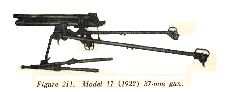
(1) The Japanese infantry is comparatevily well armed. The first effort to give heavy weapons to the infantry was 1921 - 1922, when the Model 10 (1921) 50-mm grenade discharger, the Model 10 (1921) 70-mm mortar, and the Model 11 (1922) 37-mm gun were introduced. These three weapons were later replaced by the Model 89 (1929) 50-mm grenade discharger, the Model 92 (1932) 70-mm batalion Howitzer, and the model 94 (1934) 37-mm gun. However, in some areas the older weapons are still in use.
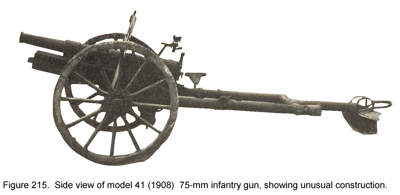
(2) In 1936, the Model 41 (1908) 75-mm mountain gun was replaced by a newer weapon in the mountain (pack) artillery units. The Model 41 gun then was issued four to each infantry regiment and is known as the regimental gun. This move gave the infantry a lightweight 75-mm weapon of its own.
(3) When first issued, Model 11 (1922) 37-mm gun was no doubt intended in part for an anti-tank role, although it could not be considered a threat today. Its successor, Model 94 (1934) 37-mm gun, has a much higher velocity.
(4) It was not until 1937, however, that the Japanese produced a purely antitank weapon. Model 97 (1937) 20-mm antitank rifle is a hard hitting mobile weapon. Model 98 (1938) 20-mm antiaircraft antitank machine cannon can also be used against tanks.
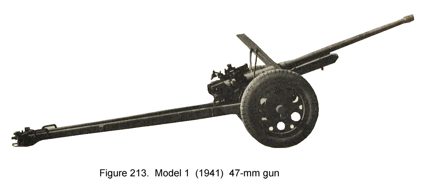
(5) With the appearance of Model 1 (1941) 47-mm gun, a modern, mobile, high velocity weapon, Japanese antitank weapons take on a much more serious aspect.
(6) The fact that Model 41 (1908) 75-mm infantry gun is provided with armor piercing, high explosive and hollow charge AP ammunition must be borne in mind, because this gun is so widely distributed in the Japanese army.
(7) Japanese infantry must be considered well supplied with heavy weapons; the Army is primarily an infantry army, and the weapons of the infantry have always been the first consideration of the military.
b. Model 97 (1937) 20-mm antitank rifle.
(1) General description. This is actually a single purpose, selective full or semi-automatic gas operated, antitank automatic cannon (fig. 209). Infantry can maneuver it in any sort of terrain. Two men can carry it, since it weighs but 150 pounds complete with shield and carrying handles, and it is easy to hide because of its low silhouette (16 1/2 inches without the shield). However, its sights do not permit accurate laying for the longer ranges, and tracking is difficult because traversing must be accomplished by shoulder control. In addition the weapon has a very violent recoil. The Japanese markings
 which mean "97 Model" appear on top of the receiver.
(2) Characteristics.
|
|
(3) Ammunition. Armor piercing tracer and high explosive tracer ammunition has been recovered.
c. model 98 (1938) 20-mm antiaircraft, antitank automatic cannon.
(1) General description. This is a gas operated, semi or full-automatic, all purpose weapon (fig. 210), similar in mechanism, but larger and heavier than the Model 97, 20-mm antitank rifle. The ammunition is not interchangeable. The cartridge permits firing from its wheels Supported on outriggers with wheels removed it has a fast 360 degree traverse.
|
(2) Characteristics. Caliber --------------------------------------------------------- 20-mm (0.79 inch). Type feed -------------------------------------- 20 round box magazine. Weight ------------------------------------------- 836 pounds (without wheels). Traverse ---------------------------------------- 6,400 mils (360 degrees). Maximum range - vertical -------------------------------------- 12,000 feet. Maximum range - Horizontal ----------------------------------- 5,450 yards. Muzzle velocity (armor piercing ammunition) ------- 2,720 feet per second. Rate of fire -------------------------------------- 120 rounds per minute. Principle of operation. -------- Gas operated, semi or full automatic. |
|
(3) Ammunition. High explosive tracer and armor piercing tracer have been recovered.
d. Model 11 (1922) 37-mm gun.
(1) General description. This weapon (fig. 211) was still in use in some areas in 1944, although its place in the infactry organization has been taken by Model 94 (1934) 37-mm gun and other antitank weapons. It resembles the U.S> 37-mm infantry gun, M 1916. The gun is carried by four men. This weapon is listed by the Japanese as
which is translated "11th year model low trajectory
infantry gun".
(2) Characteristics.
|
|
e. Model 94 (1934) 37-mm gun.
(1) General description. This weapon (fig.212) is referred to by the Japanese as the "Infantry rapid fire gun". It is an infantry close support weapon firing both high explosive and armor piercing high explosive ammunition. It has a semiautomatic, horizontal, sliding type breechlock. When the shell is loaded, the rear of the cartridge case trips a catch that closes the breechlock. Recoil action of firing opens the nreech and extracts the cartridge case. Sighting is by a straight telescoopic sight. This weapon has marked on the varrel the following
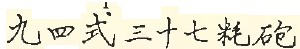 which reads "94 model 37-mm gun".
|
(2) Characteristics. Caliber --------------------------------------------------------- 37-mm (1.46 inch). Length (over all in travelling position) -------------------- 114 inches. Width (overall in travelling position) ----------------------- 47 inches. Weight ------------------------------------------- 714 pounds. Traverse ---------------------------------------- 1,062 mils (60 degrees) Elevation ---------------------------------------- +480 mils (27 degrees) Maximum range ----------------------------------- 5,000 yards. Muzzle velocity (armor piercing ammunition) ---------- 2,300 feet per second. |
|
f. Model 1 (1941) 47-mm gun.
(1) General description. This is an antitank weapon of modern design (fig 213). The wheels are independantly sprung, and a lock is provided in each wheel for locking the springs out of action. It has a semiautomatic, horizontal, sliding wedge bridge mechanism. The low silhouette, wide tread, and long split trails give this gun excellent stability. Preliminary tests indicate a muzzle velocity of 2,700 feet per second. The steel wheel discs are outfitted with sponge rubber filled tires. This weapon has marked on its breech the following symbols
 which mean "Model 1 47-mm mobile gun".
|
(2) Characteristics. Caliber --------------------- 47-mm (1.85 inch). Weight ---------------------- 1,600 pounds. Traverse -------------------- 60 degrees. Elevation -------------------- +19 degrees. Depression ------------------ -11 degrees. Muzzle velocity ------------- 2,700 feet per second. |
|
(3) Ammunition. Armor piercing high explosive and standard high explosive shells have been recovered.
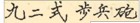
g. Model 92 (1932) 70-mm Howitzer (batallion gun).
(1) General description. This weapon (fig. 214), despite its unusual appearance, has proved to be effective as an infantry support Howitzer. It has an interrupted thread type, drop breech block mechanism. Light in weight and maneuverable, it fires a projectile of relatively large weight, and can deliver fire at ranges varying from 110 yards to 3,000 yards. The Japanese markings
 which
read "92 model infactry gun", appear on the barrel.
which
read "92 model infactry gun", appear on the barrel.
|
(2) Characteristics. Caliber ------------------------------------ 70-mm (2.76 inch). Total weight in action ------------------ 468 pounds. Thickness of armor shield -------------- 0.156 inch. Traverse ---------------------------------- 800 mils (45 deg total). Elevation -------------------------------- +50 deg. Depression ------------------------------- -10 deg. Range ------------------------------------- 3,075 yards. Danger area of burst ------------------- 40 yards (approximately). |
|
(3) Ammunition. The ammunition is semifixed,the propelling charge being divided into four increments. High explosives, armor piercing, and smoke shells are fired. The standard model 88 delat and instantaneous fuzes are used.
h. Model 41 (1908) 75-mm Infantry Gun.
(1) general description . This weapon (fig. 215) was originally the standard pack artillery weapon, but when it was largely superseded by the Model 94 (1934) 75-mm mountain (pack) gun, it was then used as an infantry "regimental" gun. It is widely distributed throughout the Japanese Army. It has an interrupted screw type breechblock and a hydro spring recoil mechanism. There are no equalizers or equilibratiors. The markings
 which appear on the barrel, mean 41 mdoel mountain gun". This weapon may be easily and quickly
disassambled for pack into loads. The maximum weight of each being approximately 200 pounds. Actual firing of the weapon at a range of 3,200 yards
resulted in 75 percent of the rounds falling in a rectangle 20 by 30 yards. At maximum range (7,800 yards) 75 percent of the rounds fell within a
rectangle 100 yards wide and 200 yards long.
which appear on the barrel, mean 41 mdoel mountain gun". This weapon may be easily and quickly
disassambled for pack into loads. The maximum weight of each being approximately 200 pounds. Actual firing of the weapon at a range of 3,200 yards
resulted in 75 percent of the rounds falling in a rectangle 20 by 30 yards. At maximum range (7,800 yards) 75 percent of the rounds fell within a
rectangle 100 yards wide and 200 yards long.
(2) Characteristics.
|
|
(3) Ammunition. Ammunition recovered included comm,on high explosive, armor piercing, sharpnel, hollow charge AP and incendiary. For description of the incendiary shell see Chapter 9, Section V.
SECTION III - WWII JAPANESE ARTILLERY
1.GENERAL
Between 1925 adn 1936, all Japanese artillery pieces were either redesigned or replaced by newer designs. An examination of a majority of the designs known to exist leads to the belief that the following features will be incorporated in any newer designs produced since 1936, although no weapon over 47-mm in size and bearing a model date later than 1936 as yet have been reported:
- Hydropneumatic recoil system.
- Use of equilibrators.
- Muzzle breaks.
- Increased muzzle velocities.
- Improved high speed mounts on all medium and heavy pieces (using either pneumatic tires or tires filled with sponge rubber).
Since Japan has had access to German weapon design for some years, it may be assumed that the Japanese weapons embodying the following features may be encountered:
- Hollow charge projectiles.
- New incendiuary projectiles.
- Self propelled mounts of various kinds.
- Rockets.
2. FIELD ARTILLERY.
a. Model 94 (1934) 75-mm mountain (pack) gun.
(1) General description. This is the standard Japanese pack artillery piece (figure 216) which replaced the Model 41 mountain gun. Designed for rapid assembling and dismantling, it breaks down into 11 units, the heaviest of which weighs 210 pounds. The weapon is normally transported by 6 pack horses. It is characterized by a comparatively long split-trail hydropneumatic recoil mechanism, and a horizontal sliding breechblock. The shield is 1/8-inch armor plate.
(2) Characteristics.
(3) Ammunition. HE, AP, sharpnel, chemical, star, and incendiary. |
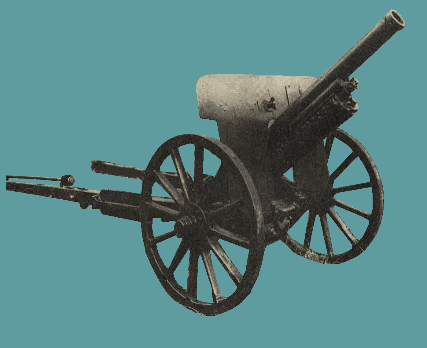
Figure 216. Model 94 (1934) mountain (pack) gun. |
b. Model 38 (1905) 75-mm gun.
General description.
(1) One of the early weapons of the Japanese division artillery, this weapon (figure 217) has been subject to considerable modification, and several versions are known to exist. There is no evidence that this parent model has been employed in recent operation; probably now it is regarded as obsolete (1944). It may be readuly identified by the single box trail which, by its design, considerably limits the elevation of the piece. Other characteristics are a hydrospring recoil system, interrupted screw type breechlock, and 1/16-inch shield.
2. Characteristics.
(3) Ammunition. HE and AP. |
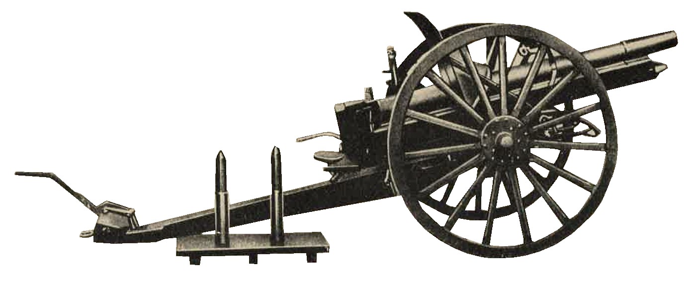
Figure 217. WWII Japanese 75-mm gun with ammunition. |
c. Model 38 (1905) gun improved (possibly 4th year model).
(1) General description. This is an improved version of the 75-mm model 38 (1905) field gun, which appears to have been entirely replaced. Modifications on the present model (figure 218) consists of trunnioning the barrel further to the rear; the addition of two spring and cable equilibrators to compensate for muzzle overhang; Replacement of the old box trail by a longer open box type through which the barrel can recoil at high elevations; change the breech to a horizontal sliding wedge mechanism, the most significant results of the above modification are a much longer range and increase rate of fire. Although reports have indicated that this weapon was to be replaced by the Model 90, the fact that the newer gun has not been encountered in any combat areas (as of 1944) indicates that this plan has not yet beeb consummated.
(3) Ammunition. HE, AP, sharpnel, smoke, star shell, and chemichal. |
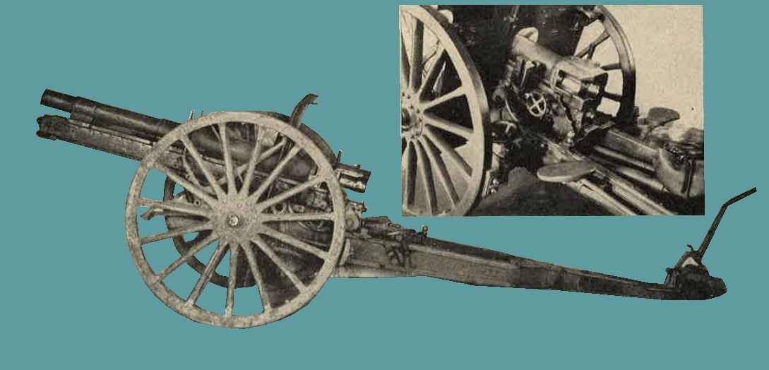
Figure 218. Japanese Model 38 (1905) gun improved (Insert shows breech mechanism). |
d. Model 90 (1930) 75-mm gun.
(1) Geenral description. Surrounded with considerable secrecy by the Japanese, this gun (figure 219) has been reported as the modern weapon of the division artillery. In 1936 it was believed to have been in process of issue to organizations, but to date (1944), it has not been encountered in any theater of war.
The gun is equipped with either pneumatic tires for motorized towing or large , steel-rimmed wheels for horse draft. It is characterized by a split trail, a horizontal sliding breechlock, and a hydropneumatic recoil system. An ususual feature is the muzzle break, which as of 1944, it had not been found on any other artillery piece.
(3) Ammunition. HE, AP, sharpnel, incendiary, smoke, star shell. |
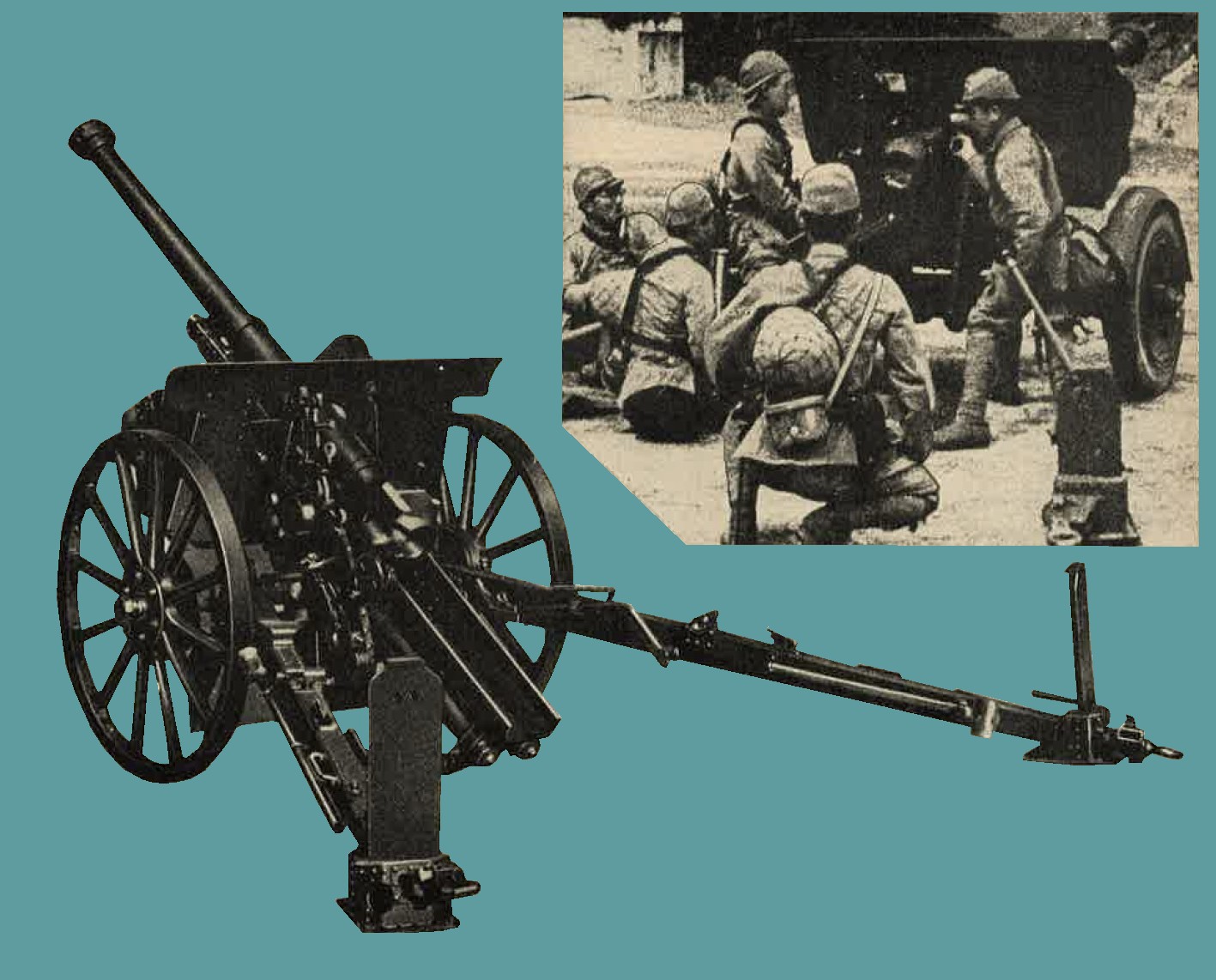
Figure 219. WWII Japanese Model 90 (1930) 75-mm gun (insert shows the weapon on a high speed carriage with pneumatic type tires). |
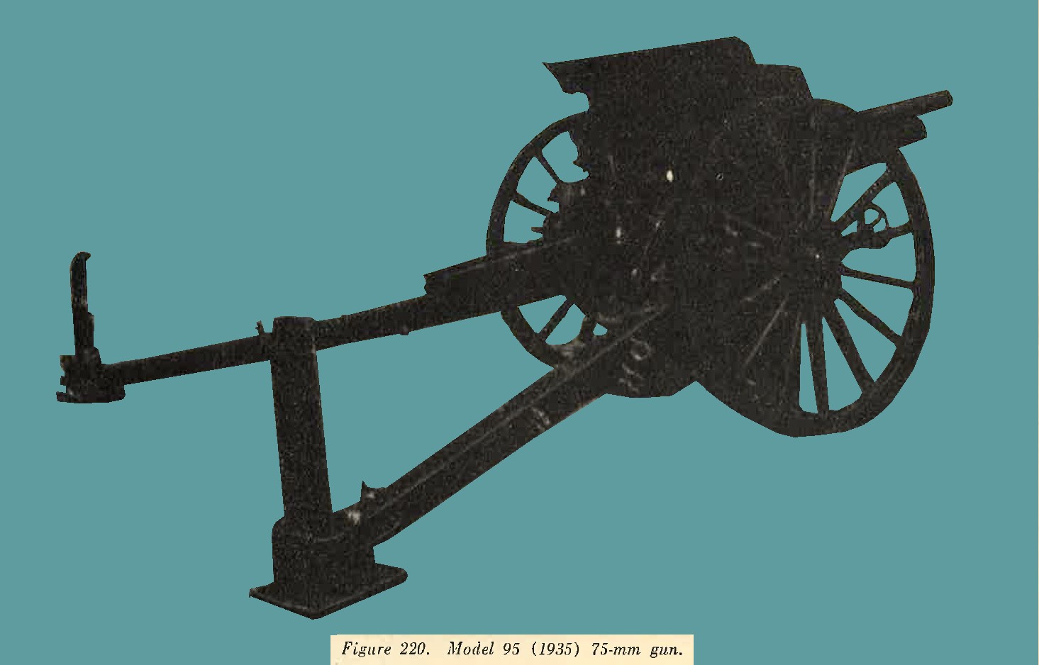
e. model 95 (1935) 75-mm gun.
(1) General description. The 75-mm Model 95 gun is a horse drawn (figure 220) with split trails, hydropneumatic recoil mechanism, and horizontal, sliding-wedge type breechlock. A comparison with the Model 90, designed 5 years earlier, reveals that this later weapon has only the apparent advantage of reduced weight. On the other hand, it suffers from loss of range and lower muzzle velocity. It is seemingly more rugged in construction than the Model 94 mountain gun and yet gives a lower performance than he Model 90 field gun.
The possibility therefore suggests itself that the Model 95 was not designed to replace other of these guns, but was to be used by some unit other than the field or pack artillery. It is possible therefore that it may be the new weapon of the horse artillery, replacing the old adaptation of the Model 38 with which such units previously had been equipped.
* Also reported as 9,000 meters (9,850 yards). (3) Ammunition. HE, AP, sharpnel, smoke star and chemical. |
 |
f. Model 14 (1925) 105-mm gun.
(1) General description. The 105-mm Model 14 (1925) gun (figure 221) is used for long range fire. There is no information, as of 1944, to show that this gun is still in production, and ir is felt that in all probability it has been superseded by the more modern Model 92 (1932).
This artillery piece was mounted on heavy wooden wheels, the weapon is normally tractor drawn, and is capable of being moved at a maximum speed of 8 miles per hour. As an alternative it may be drawn by 8 horses. The weapon possesses an interrupted screw breechlock, a hydropneumatic recoil mechanism, and a split trail.
(2) Characteristics.
|
 |
(3) Ammunition. Ammunition is semifixed. The following types of projectiles have been reported:
- High explosive (long pointed shell).
- High explosive.
- Sharpnel.
- Chemical.
- Armor piercing.
Time fuses are provided for the smoke, incendiary, and sharpnel projectiles. The standard Model 88 point detonating (instantaneous or delay) fuzes are used with HE and chemical shells.
g. Model 91 (1931) 105-mm Howitzer.
(1) Genral description. A light weight modern field piece (figure 222) possessing a hydropneumatic recoil mechanism, split trail, and interrupted screw breech mechanism. The weapon can be readily identified by the short barrel and long sleigh. Normally it is towed by six horses.
|
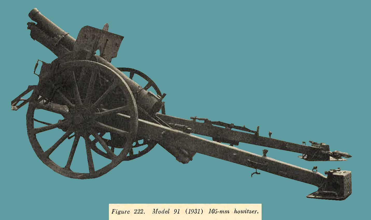 |
(3) Ammunition. Ammunition is semifixed. The following types of projectiles have been reported: - High explosive (long pointed shell).
- High explosive.
- Armor piercing.
- Sharpnel.
- Chemical.
h. Model 92 (1932) 105-mm gun.
(1) General description. It is considered that this weapon (figure 223) has superseded the Model 14 (1925) 105-mm gun. Readily recognized by its long slender barrel and trail, it has been designed [particularly for long range fire. Other distinctive features are the pronounced length of the sleigh and the three step interrupted thread breechlock. The recoil system is hydropneumatic. Mounted on heavily constructed wooden wheels with solid rubber tires, the weapon is normally tractor drawn, but may be drawn by a 5 ton truck.
|
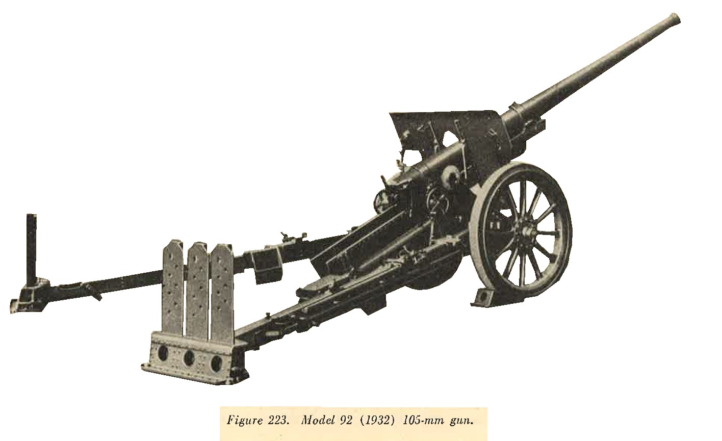 |
(3) Ammunition. Ammunition is semifixed. The following types of projectiles have been reported: - High explosive (long pointed shell).
- High explosive.
- Chemical.
- Armor piercing.
Time fuzes are provided for the smoke, incendiary, and chemical shells. The standard Model 88 point detonating (instantaneous or delay) fuzes are used with the HE and chemical shells.
i. Model 4 (1915) 150-mm howitzer.
(1) General description. One of the older type horse drawn weapons (figure 224) which nevertheless is still in service. For purposes of transportation the trail breaks in the middle. The barrel is removed from the cradle and placed on the rear portion of the trail, to which has been attached an extra pair of wheels. a limber is attached to each section, and each load may then be towed by six horses. The weapon possesses a vertical sliding breechlock, a hydropneumatic recoil mechanism, and a box type trail.
|
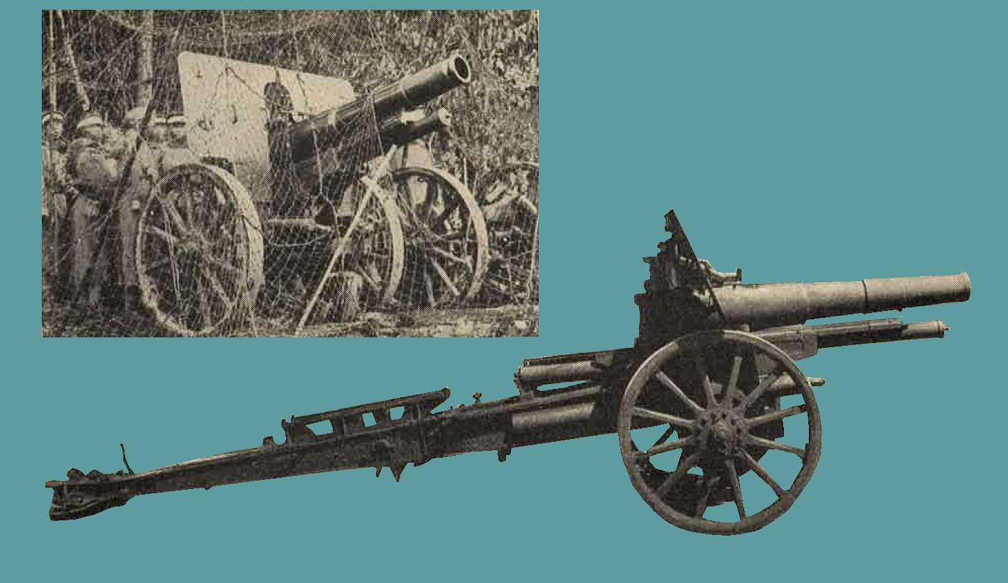
Figure 224. Two views of Model 4 (1915) 150-mm howitzer. |
(3) Ammunition. Ammunition is semifixed. The following types of projectiles have been reported:
- High explosive.
- Armor piercing.
- Sharpnel.
- Chemical.
Time fuzes are provided for the smoke, incendiary, and sharpnel projectiles. The standard point detonating (instantaneous and delay) fuzes are used with the HE and chemical shells.
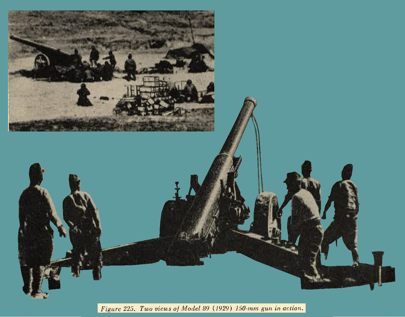
j. Model 89 (1929) 150-mm gun.
(1) General description. A tractor drawn weapon (figure 225) of improved design employed for long range fire. it is designated by the Japanese Army as a heavy field artillery piece. Although manufactured was commenced in 1929, it is believed that issue was not completed until 1937. For purposes of transportation the barrel is removed from the cradle and placed on a separate carriage. The weapon has a split trail, hydropneumatic recoil mechanism, and an interrupted thread block.
(3) Ammunition. AP, HE, Sharpnel, HE (long pointed shell). |
 |
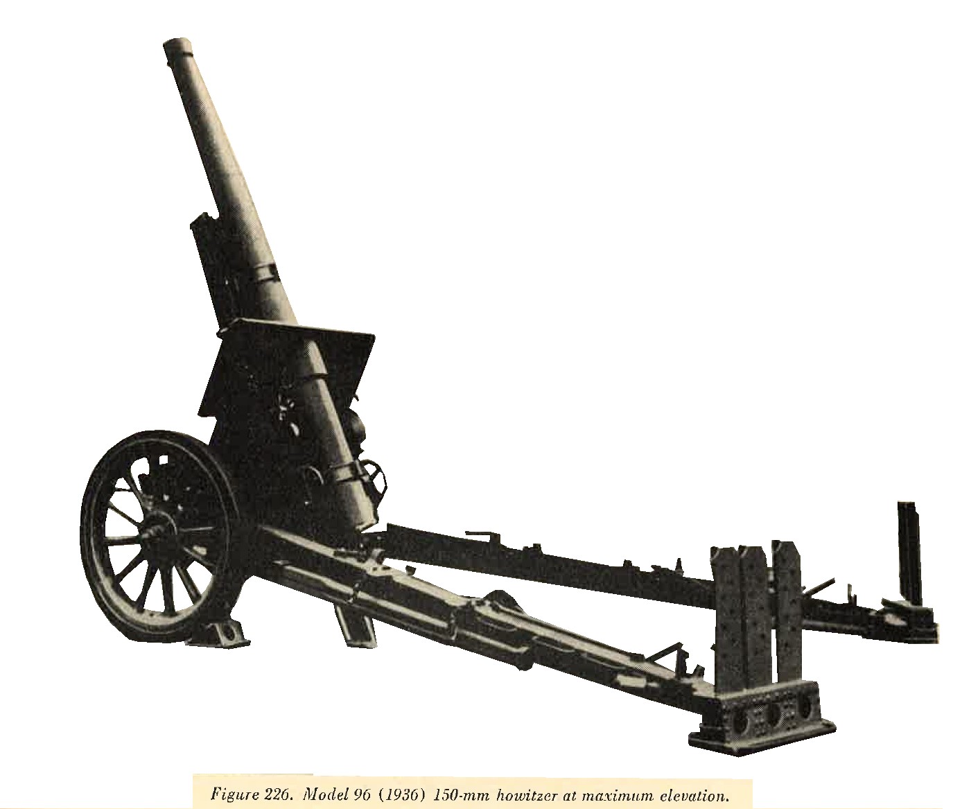
k. Model 96 (1936) 150-mm Howitzer.
(1) General description. A well designed and effective weapon (figure 226) which is, to date (1944) the most modern of its type known to be possessed by the Japanese. It is reported that three modifications exist. Variations, however, are believed to be extremely slight. Mounted on sturdy, rubber shod, wooden wheels, the weapon is normally tractor drawn. One of the outstanding characteristics is the extreme elevation of 75 degrees which can be obtained. This, however, can be used only when a deep loading pit is dug beneath the breech. It is probable that the weapon could not be fired at an elevation greater than 45 degrees without construction of such a pit. Other features are a long split trail, interrupted thread breechlock, and a hydropneumatic recoil mechanism.
(2) Characteristics.
(3) Ammunition. Semifixed; HE, AP, Sharpnel, smoke, incendiary tracer. |
 |
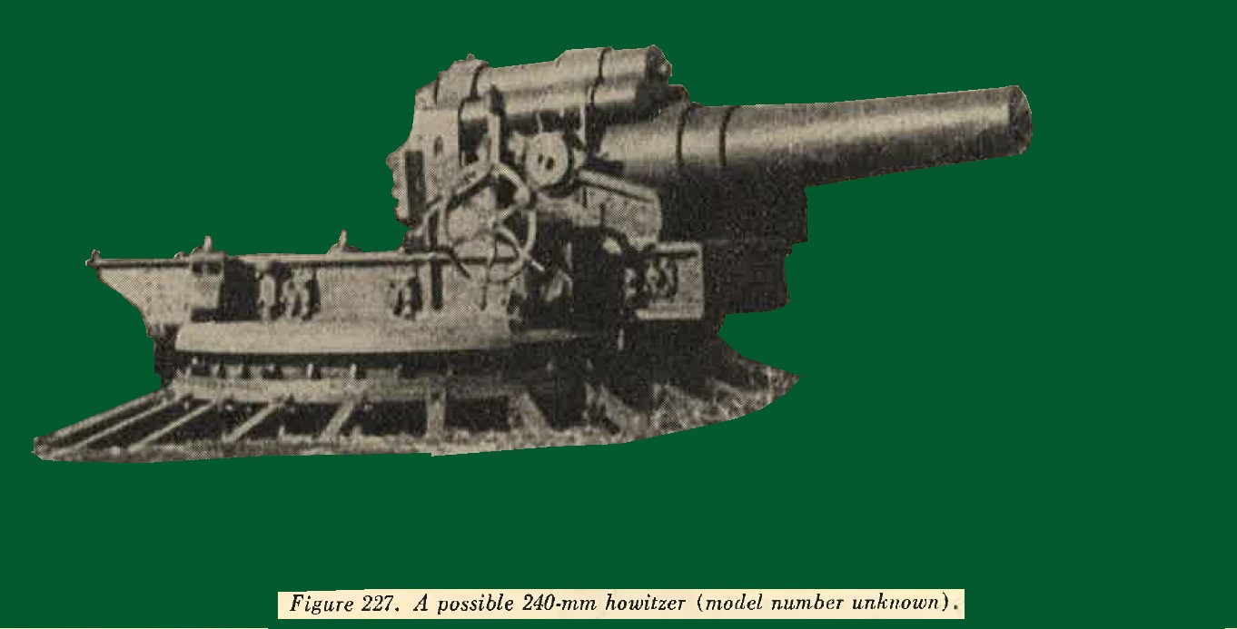
l. Model 45 (1912) 240-mm Howitzer.
It is reported that this piece has a maximum range of 11,000 yeards, firing a semifixed round weighing approximately 400 pounds. It is broken down and transported on 10 vehicles. (See figure 227).
m. Miscellaneous heavy artillery.
in recent years the Japanese have bought 17-cm, 21-cm and 24-cm weapons from Germany and therefore Japanese copies of these may be expected. In addition to the above, the following heavy artillery pieces have been reported but none have been captured, therefore the characteristics given below have not been confirmed.
| Caliber | Type | Length of bore | Muzzle velocity | Type of shell | Weight of shell | Maximum range | Elevation | Weight in action | Remarks |
| 24-cm | Railway gun | ----- | 3,560 ft/sec | HE | 440 lbs | 54,500 yrds | ----- | 35 tons | Several types reported |
| 30-cm | Howitzer M18 | 196 | 1,310 ft/sec | HE | 880 lbs | 12,750 yrds | 46 deg | 14.72 tons | Unconfirmed |
| 30-cm | Howitzer M18 | 324 | 1,140 ft/sec | HE | 1,100 lbs | 16,600 yrds | 48 deg | 19.76 tons | Do. |
| 41-cm | Howitzer (seige) | 538 | 1,760 ft/sec | HE | 2,200 lbs | 21,200 yrds | 45 deg | 80 tons | Do. |
3. WWII JAPANESE ANTIAIRCRAFT ARTILLERY.
a. Inroduction. It has been emphasized to the Japanese soldier that effective aircraft defense depends on the use of all arms. Many of the weapons primarilyt designed for ground action and previously described under infantry armament also are designed to perform an antiaircraft role.
(1) The new basic infantry weapon Model 99 (1939) 7.7-mm rifle (figure 228) has a rear sight, with arms calculated to give the rifleman the approximate lead required to hit a low flying plane.
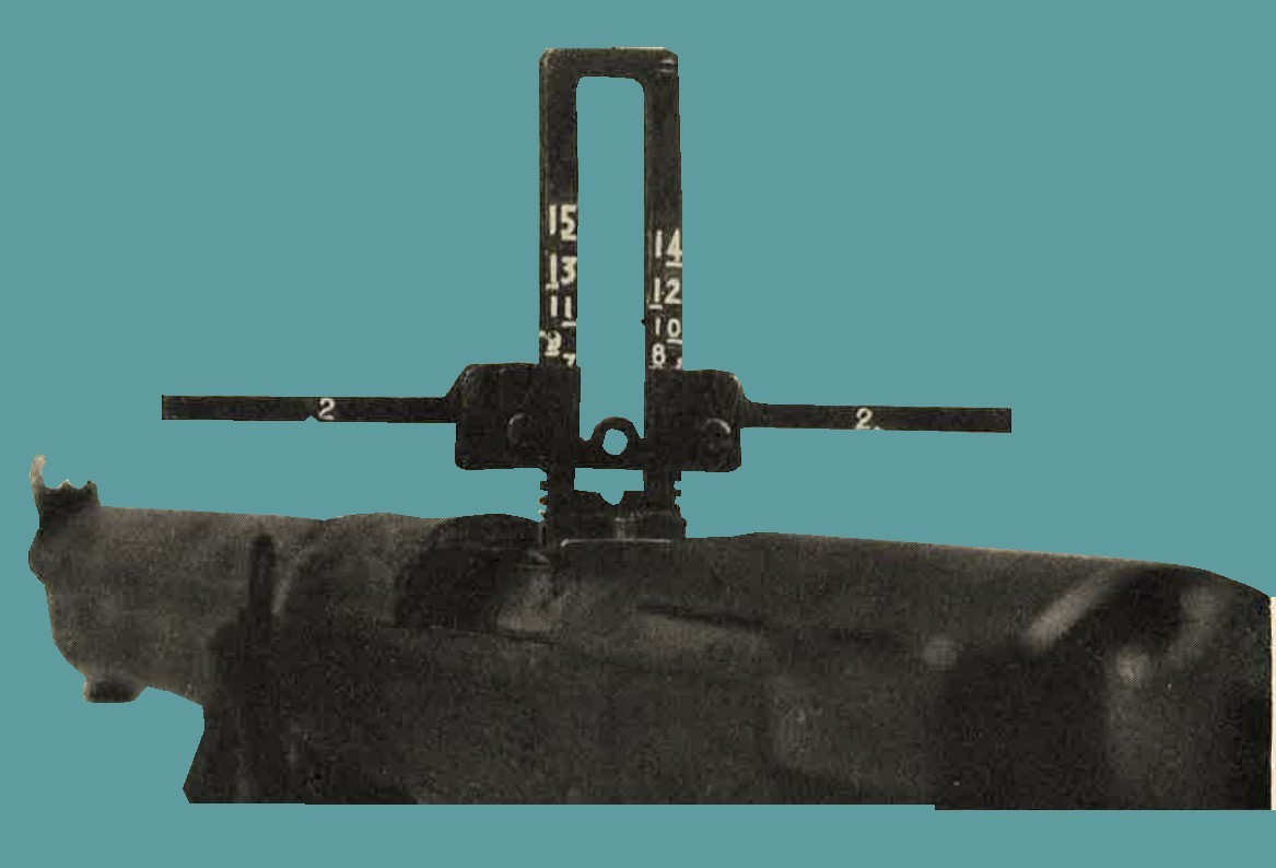
Figure 228. Rear sight on Model 99 (1939) 7.7-mm rifle.
(2) The Model 92 (1932) 7.7-mm heavy machine gun (figure 229) is provided with an antiaircraft adapter as illustrated in figure 229, and standard antiaircraft ring sights.
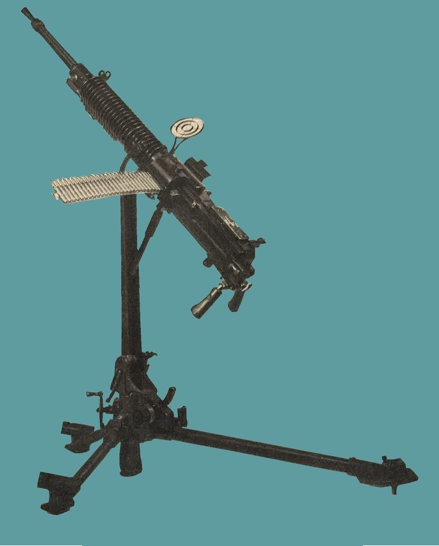
Figure 229. Model 92 (1932) 7.7-mm HMG with AA adapter.
(3) The Lewis type Model 92 (1932) 7.7-mm machine gun (figure 230) has a standard mount which can be adapted for antiaircraft defense (see figure 230)
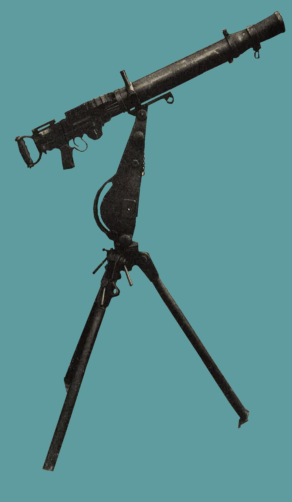
Figure 230. Model 92 (1932) 7.7-mm machine gun (Lewis type) in position for AA fire.
(4) The Model 93 (1933) 13-mm machine gun is shown in figure 231 in dual mount for antiaircraft fire.
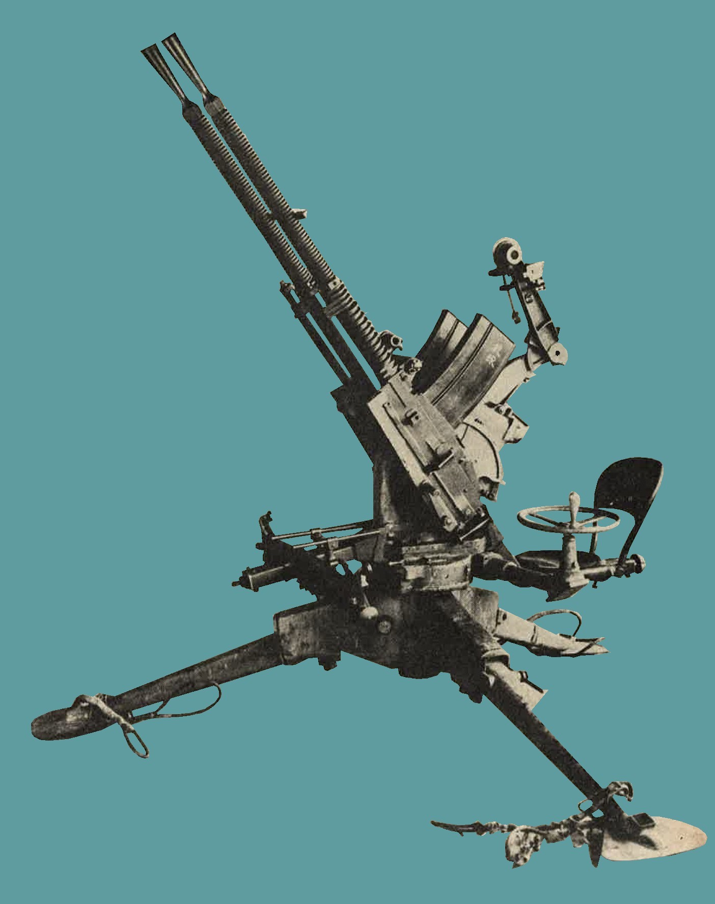
Figure 231. Model 93 (1933) 13-mm machine gun (dual mount).
(5) The Model 98 (1938) 20-mm AA/AT automatic cannon and probably the 70-mm barrage mortar (Chapter 9, Section II) have been designed principally for an antiaircraft role.
(6) In addition to the more common antiaircraft weapons described in detail on the following pages, 120-mm and 127-mm naval antiaircraft guns have been encountered. Th elatter in dual mounts.
(7) There are indications that Japanese heavy AA artillery is possibly more modern and a larger caliber than the standard 75-mm model 88, which is the only heavy antiaircraft weapon captured in quantity to date.
(8) Tabulated below are the estimated capabilities of Japanese aircraft weapons.
| NUM | CALIBER | WEAPONS | MAXIMUM RATE OF FIRE | MAXIMUM VERTICAL RANGE |
| 1 | 7.7-mm | Model 92 heavy machine gun | 450 | 4,000 |
| 2 | 7.7-mm | Model 92 (Lewis) machine gun | 600 | 4,000 |
| 3 | 13.2-mm | Model 93 machine gun | 450 | 13,000 |
| 4 | 20-mm | Model 98 automatic cannon | 200 | 12,000 |
| 5 | 25-mm | Model 96 naval automatic cannon | 300 | 14,000 |
| 6 | 40-mm | Vickers type | ----- | 14,000 |
| 7 | 75-mm | Model 88 gun | 15 | 30,000 |
| 8 | 105-mm | Model 14 gun | 10 | 36,000 |
| 9 | 127-mm | Model 89 gun | 10 | 40,000 |
Information concerning fire control equipment used with some of the weapons listed will be found in Chapter 10.
b. Model 96 (1936) type 2, 25-mm antiaircraft - antitank automatic cannon.
1. General description. This (Figure 232) is gas operated, air cooled, magazine-fed, full automatic,or semiautomatic machine cannon. It has been been found in dual and triple fixed mounts, emplaced customarily around air strips for antiaircraft defense. However, it is capable of 10 degree depression which makes it effective for direct fire against ground targets. Traverse and elevation are controlled by hand wheels.
2. Characteristics.
|
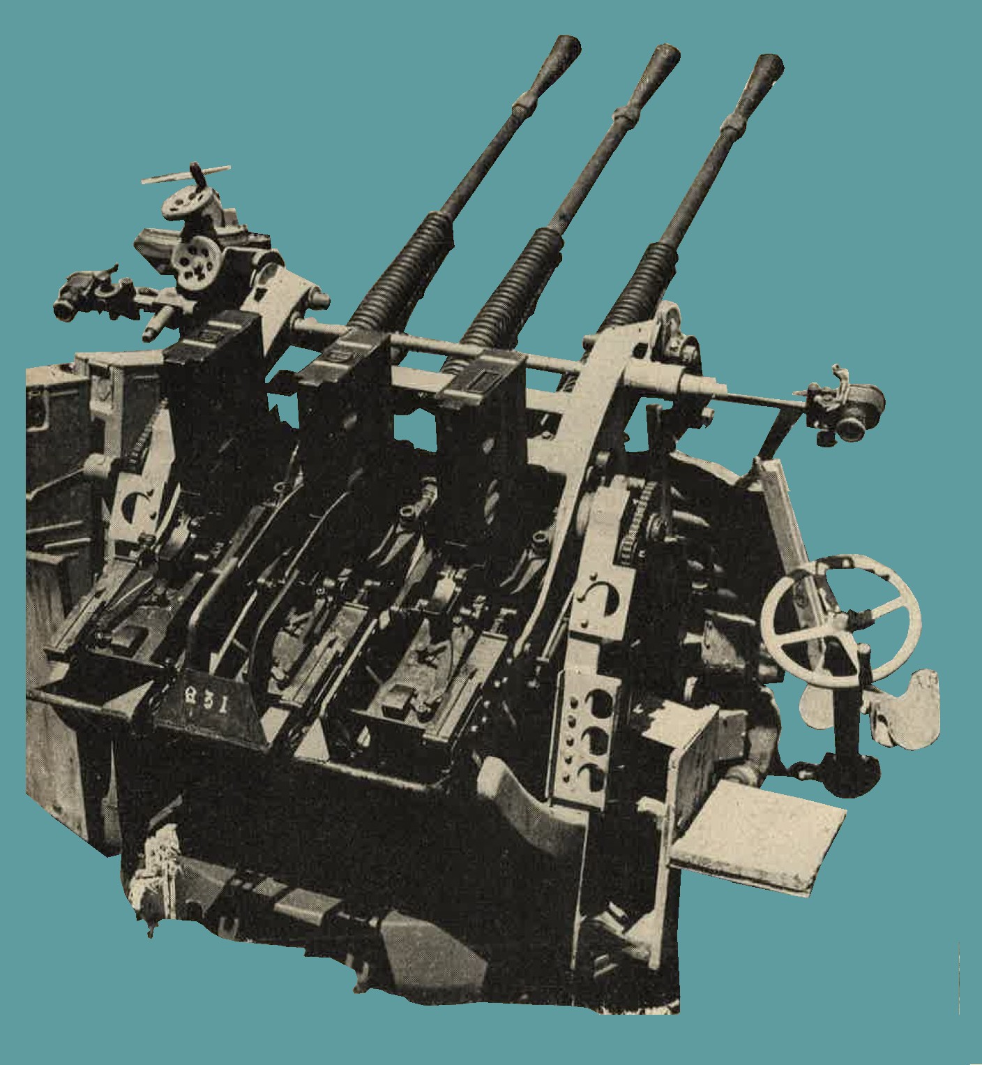
Figure 232. Rear view of Model 96 (1936) type 2, 25-mm AA/AT automatic cannon, triple mount. |
3. Ammunition. This weapon is furnished with high explosive tracer, high explosive, and armor piercing tracer ammunition.
c. 40-mm single and dual antiaircraft and antitank automatic cannon.
(1) General description. This weapon (figure 233) is a Vickers type recoil operated, water cooled, link belt fed, automatic or semiautomatic machine cannon. several of these have been captured. Single mounted guns were marked "Vickers - Armstrongs 1931", but the dual mounted guns were Japanese manufactured copies. Elevation and traverse are obtained by hand. The weapon is fitted with a telescopic calculating sight and an automatic fuze setter.
(2) Characteristics.
(3) Ammunition. Armor piercing high explosive, high explosive with time fuze, high explosive with point detonating fuze, and tracer. |
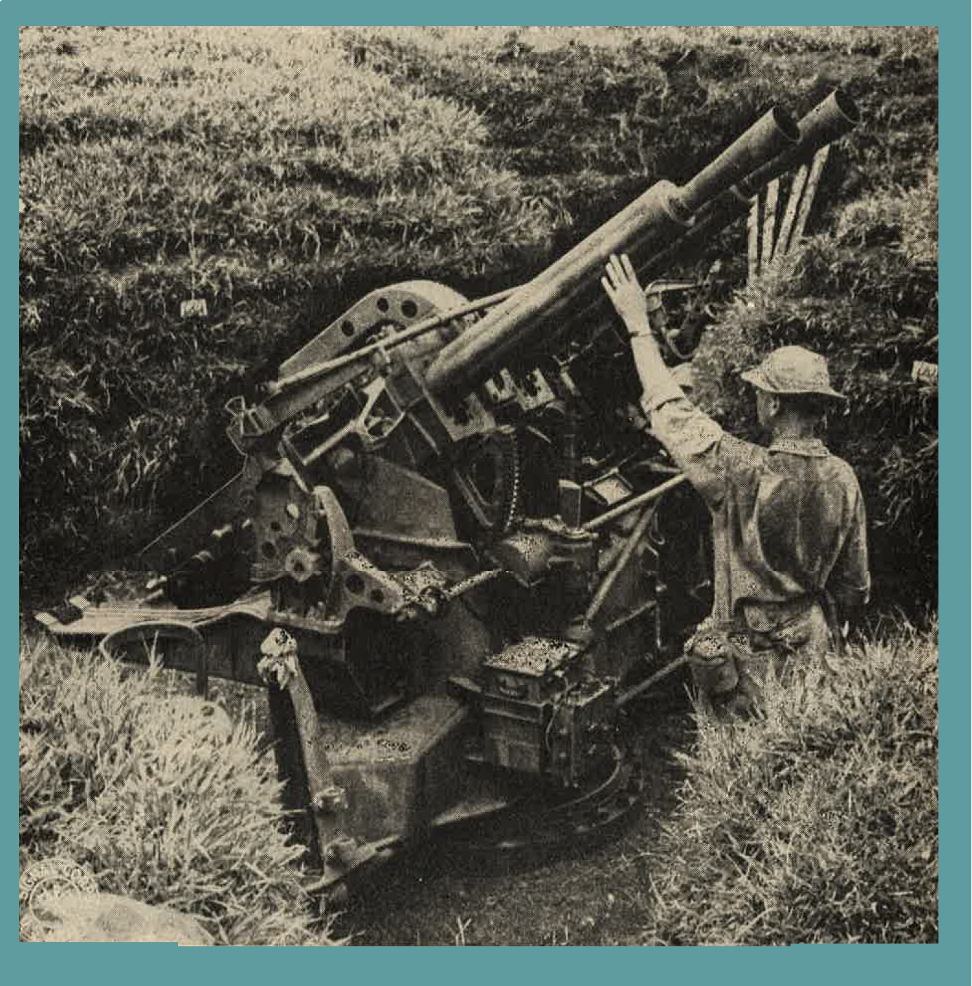
Figure 233. Dual mounted 40-mm Vickers type 40-mm AA/AT automatic cannon. |
d. Model 88 (1928) 75-mm antiaircraft gun.
(1) General description. This has been the standard Japanese mobile heavy antiaircraft weapon (figure 234). Specimens have been found on all airfields captured from the Japanese. It is a truck drawn weapon. For firing, the wheels are removed, and the gun is supported by five outriggers. During transit, the barrel is dropped back on the cradle extension and secured to the ends of two outriggers. The gun has a hydropneumatic variable recoil system and a semiautomatic horizontal, sliding wedge breech mechanism. Fire control instruments captured indicate that the older system of transmitting corrections to the gun pointers vocally is still in use. However, evidence is on hand that an electrical data transmission system and operation by the "Matched Pointers" method is used sometimes. This gun has been used against ground targets.
(2) Characteristics.
(3) Ammunition. High explosive, sharpnel, and incendiary. |
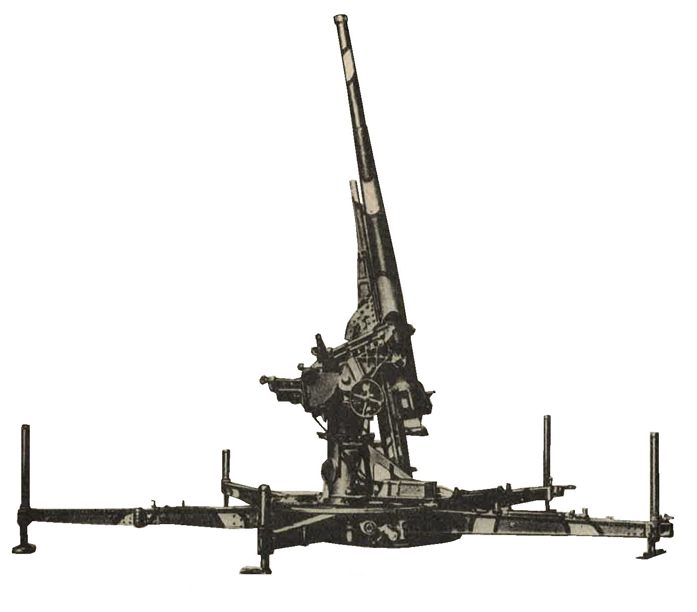
Figure 234. Model 88 (1928) 75-mm antiaircraft gun. |
e. Model 14 (1925) 105-mm antiaircraft gun.
(1) General description. This is the heavist mobile Japanese antiaircaft weapon (figure 235) in use at present (1944). As originally designed, it was not satisfactory, and probably has been redesigned by this time. It has a pedestal mount, horizontal sliding breechblock, and a hydropneumatic recil system. In firing position the wheels are detached and the gun rests on six outriggers. Thiry to 45 minutes are required to prepare the gun for action. The fuze setter is continuous and automatic.
(2) Characteristics.
(3) Ammunition. High explosive. |
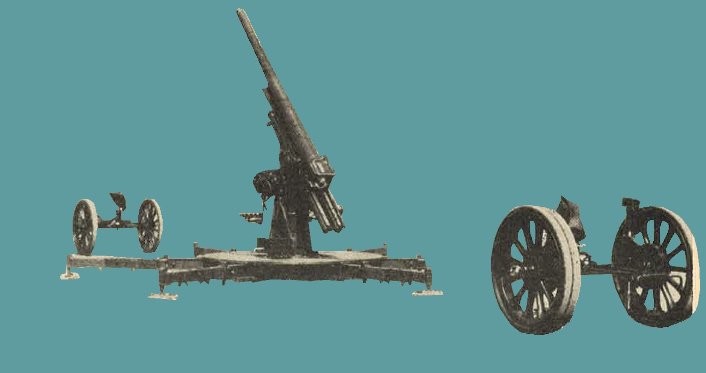
Figure 235. Model 14 (1925) 105-mm antiaircraft gun showing detachable wheels used for transport of piece. |
4. NAVAL WEAPONS.
a. General In all areas captured from Japanese, naval guns have been found installed for coastal and antiaircraft defense. These weapons have been of standard naval design, and in many cases appear to have been removed complete (including turret, mounting, etc.) from the decks of the ships. It is known that the Japanese have recovered the armamentfrom beached ships and transferred them to land posiitons.
Since they are on pedestal mounts with wide traverse, they not only are used for coastal defense but also may be brought to bear against inland targets. On the following pages are found examples of the naval guns which are most likely to be encountered. Of these weapons the Model 10 (1921) 3-inch gun has been most frequently installed. In addition to thoseweapons described, guns of 127-mm (5 inch) and 8 inch calibers have been captured. The 127-mm guns have been found mounted in pairs in turrets which permit antiaircraft fire.
b. Model 10 (1921) 3-Inch gun.
(1) General description.
The Japanese refer to this weapon (figure 236) as the "8-cm, 40 caliber, high angle gun". actual measurements show it to be 76.2-mm (3 inch). A dual purpose piece of pedestal mount, it is used as antiaircraft as well as coastal defense. To compensate for muzzle preponderance, an equilibrator is mounted in the pedestal. The recoil system is hydropneumatic, and the breechblock is the sliding wedge type. A noticeable feature is the unusually long recoil cylinder on the top of the tube.
(2) Characteristics.
(3) Ammunition. High explosive. |
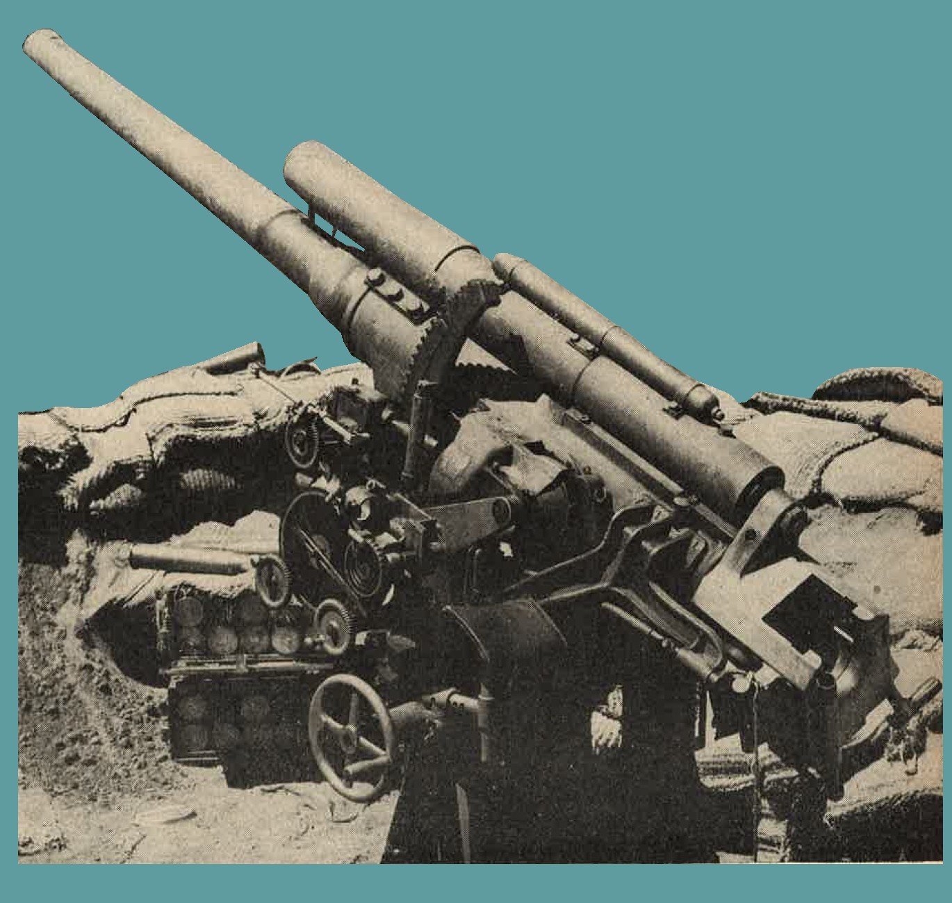
Figure 236. Model 10 (1921) 3-inch gun. |
c. Model 3 (1914) 12-cm Naval gun.
(1) General description.
Guns of this type (figure 237) have been encountered on a number of islands in the Pacific area. No provision has been made on the gun illustrtated in figure 237 to provide for use as an antiaircraft weapon, but other weapons of this caliber allegedly are munted for such purposes. It has a hydropneumatic recoil system and an interrupted thread breechblock.
(2) Characteristics.
(3) Ammunition. Separate loading high explosive with a cartridge case used for obturation. |
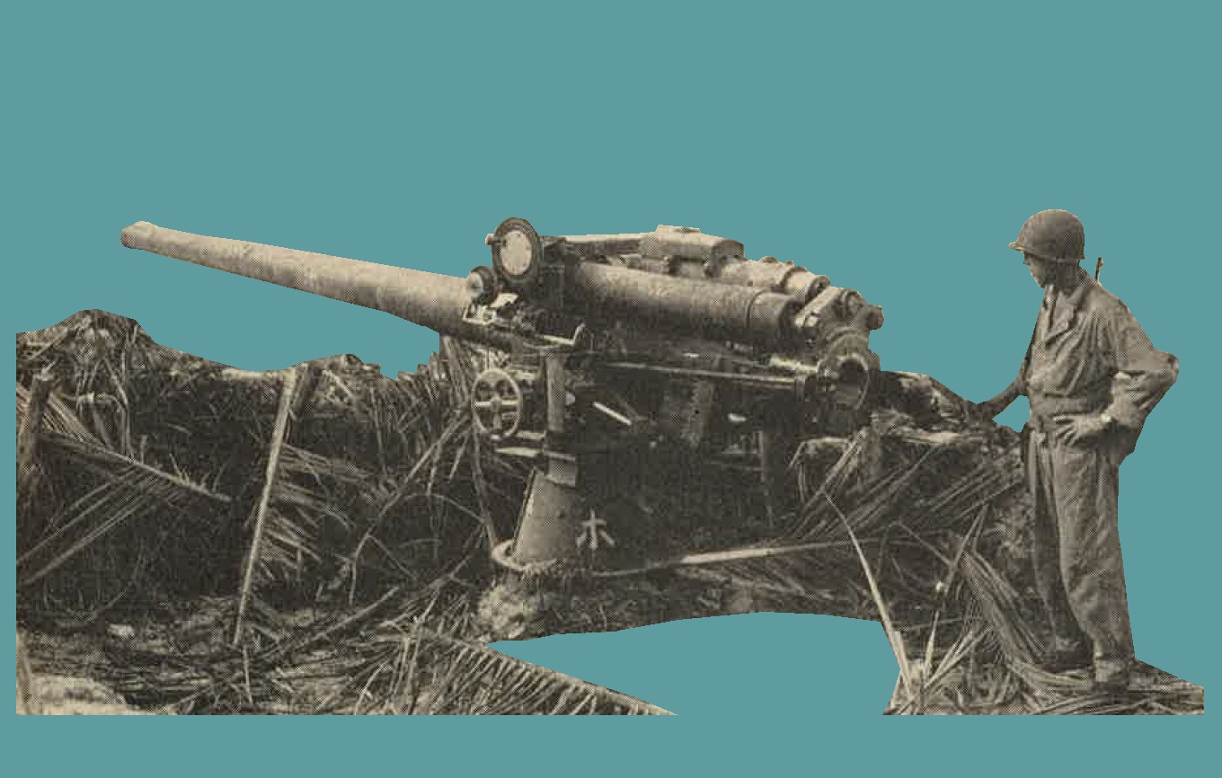
Figure 237. Model 3 (1914) 12-cm naval gun. |
d. Model 3 (1914) 14-cm naval gun.
(1) General description.
An orthodox type of naval gun and pedestal mount (figure 238) which has been used as a coastal defense weapon. It has been found both with a shield and mounted in a hand operated turret (casemate). It has a hydropneumatic recoil system and truncated cone, interrupted thread breechblock.
(2) Characteristics.
(3) Ammunition. Separate loading ammunition is used. The prokectiles recovered were high explosive, with fuzes designed for use against vessels. |
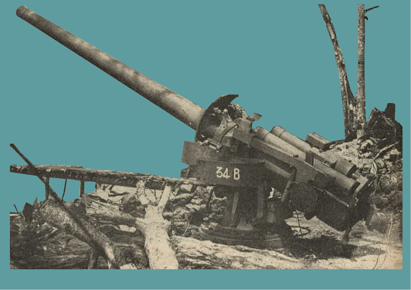
Figure 238. Model 3 (1914) 14-cm naval gun. |
SECTION IV - WWII JAPANESE TANKS AND ARMORED CARS
1. GENERAL.
Until 1929 Japan di dnot produce any tanks ( Sensha ) of her own. As usual, her ideas were borrowed from the West, particularly from the British and French, and her first tanks were versionsof early Renault, Vickers, and Carden-Lloyd models. Later she turned to Russia for new developments.
Prior to 1941 the Japanese had every opportunity to study and the experience of the Allies in war, and it is also reasonable to assume that they are still borrowing freely from other nations. During 1935-37 the Japanese apparently were concentrating on tankettes, light tanks, medium tanks, perfecting one model in each class. It is probable that a few heavy tanks also were produced. Their tanks fall into four main types, divided according to weight. These are:
|
a. Tank nomenclature. For purposes of general information, annoted photographs illustrating various items of tank nomenclature, are reproduced in figure 239.
 |
 |
b. horsepower. Horsepowers indicated throughout the following text are all Japanese ratings. In each instance, engines have been examined (e.g. M 2595 Light Tank and M 2597 Medium Tank) it had been clearly shown that they are capable of developing a considerable greater degree of power than that reported. Consequently, wherever possible, theoretically indicated horse powers, derived from computations based on engine specifications, have been shown.
c. Crews. Crew compartments so far examined are limited in size, and little attention has been given to comfort. The turret and hulls, however, have been found to be well insulated with material such as asbestos.
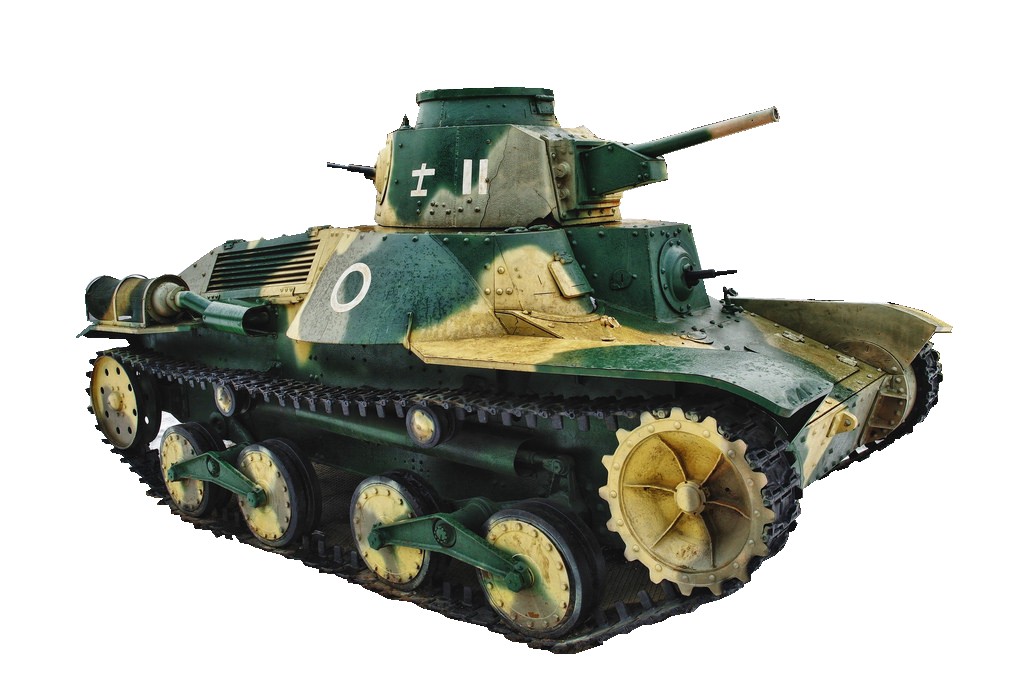
d. Armament. In the light and medium tanks, relatively low velocity 37-mm and 57-mm guns are used. There is also evidence that a 47-mm gun is used in medium tanks. Although a machine gun is normally mounted in the rear of the turret, and is of some tactical use, it is doubtful if the main turret weapon and rear machine gun can be fought at the same time. The use of armored sheaths is standard for all machine gun barrels. All machine guns are ball mounted, adn the main turret armament has a limited traverse, independent of that of the turret. In both the light and medium tanks a hull machine gun is mounted.
e. Armor. Japanese tanks, so far examined, have been lightly armored, but the plates tested have been of good quality. In the arrangement of armor, use has been made of deflection angles, but not to any considerable degree. In many cases reentrant angles have been formed, but no steps have been noted to protect turret rings or mantlets against jamming or splash.
f. Engines. Diesels are mainly used.
g. Suspension. In all these models the same basic suspension is used. This consists of bell crank arms carrying rocking pairs of wheels. These arms are sprung by horizontal suspension springs, protected by armored casings,
h. Vision. Little use has been made of periscopes, etc., vision being dependent on slits, occassionally backed by a glass block.
i. Doors. The question of escape in case of fire or other emergencies has been given little attention.
j. Communications. As far as known, radio is only used on basis of 1 set per platoon in the medium tanks, and probably not at all in light tanks and tankettes.
k. Insignia. Army tanks have a 5 point star mounted on the front, whike navy tanks have the anchor insignia. Many tanks either fly or carry the national flag as an identification sign. Naval tanks usually have the small naval insignia painted on the sides.
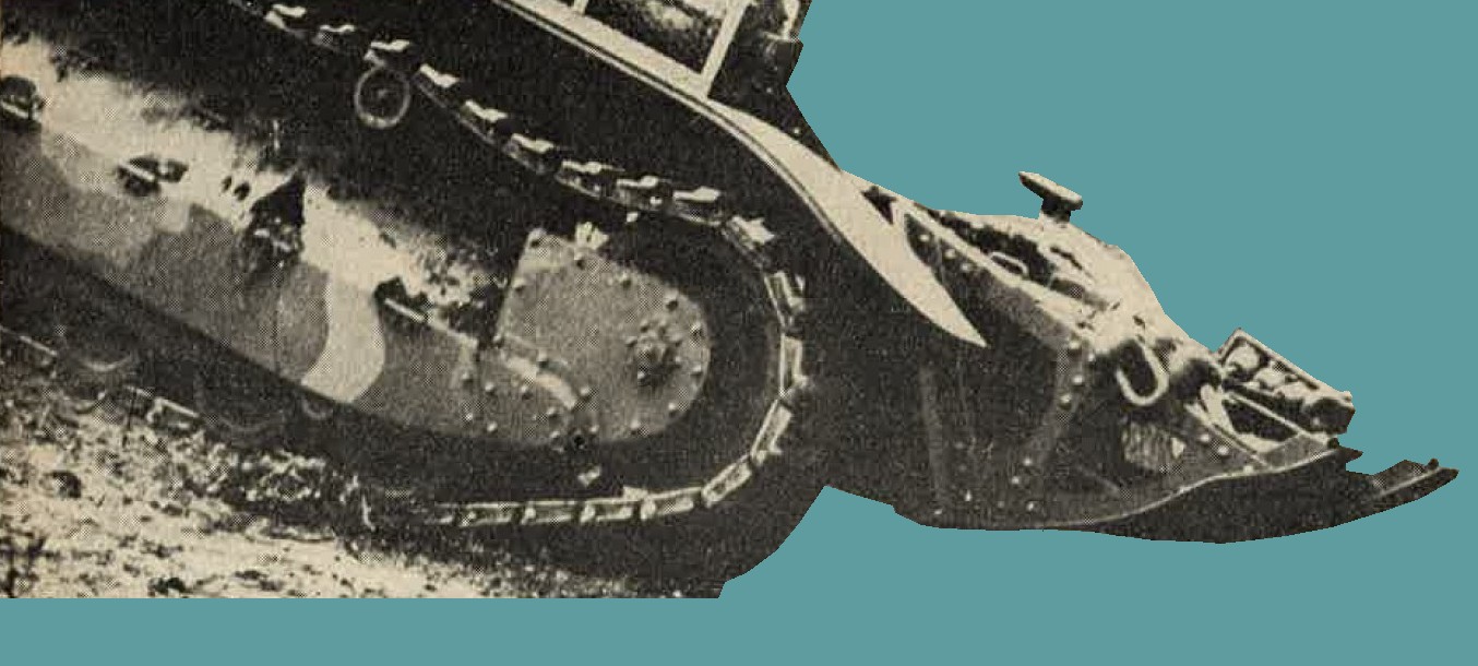
Figure 239. Tank rear end.
l. Future developments.
(1) General. It would be dangerous to measure Japanese tanks buy models now (1944) known to exist. Evidence exists that Japan is in close touch with German developnment, and it may well prove that Japanese tanks will show considerable German influence. That Japanese tank design is not stagnant is clearly indicated by the recently captured new type amphibious tank described in this section. In this particular tank the coaxially mounted machine gun is considered of significance. Hitherto, there has been no evidence that the Japanese have mounted weapons in this manner, so it must be considered indicative of a new trend.
(2) Armament. High velocity antitank guns, of at least 75-mm caliber, and modern high performance armor piercing high explosive ammunition, as well as hollow charge types, may be expected. As a temporary measure, earlier model tanks, such as the medium which mounts a 57-mm gun, could be given a new lease of life in a tank role by providing hollow charge ammunition.
(3) Armor. Early model tanks may be fitted with additional plates at vulnerable points; modern tanks can be expected to have heavier armor. Armor angles can be expected to receive more attention.
(4) Performance. So far Japan has used high power weight ratios. If these are maintained, high speeds and good cross country mobility will result. Suitable preparations, depending on tactical roles, may be undertaken to increase fording ability.
(5) Communication. Radio may be introduced down to individual tanks.
(6) Other improvements. Special items, like vision aids, escape facilities, and gun fume extraction may be developed. As an illustration of the trend in tank improvements, in teh new type amphibious tank, many of the objectionable features of the older designs have been overcome. Reentrant angles have been eliminated, while the hull design has been simplified and welded construction used throughout. In addition, firepower has been improved by the substitution of a highly velocity 37-mm weapon and the coaxial mounting of a machine gun.
(7) Heavy tanks. The Japanese are capable of designning an efficient, modern, heavy tank, but it is thought that they may have difficulty in its quantity production. In the past Japanese have produced a number of heavy tanks which muct now be considered obsolete.
m. Miscellaneous types. Reports suggest that Crane, Repair, and Supply tanks may exist. These are believed to consist basically of tank chassis, less the turret, and fitted out according to requirements.
2. WWII JAPANESE TANKETTES.
a. Tankette Model 92 (1932). Development of the tankette has been progressive. In China it was used on a wide scale by Japan in a cavalry and reconnaissance role. In addition it is employed for towing tracked trailers carrying supplies and ammunition. Both welded and riveted construction are used throughout the hull (figure 240). The suspension is an early Japanese development. Four point suspension of the hull is achieved by use of bell cranks, resisted by armored compression springs on each side. Four rubber tired bogie wheels, two return rollers, and outside cebter guide tracks are used. Front sprocket drive and left rear mounted engine are employed.
Approximate specifications
|
Approximate maximum performance
|
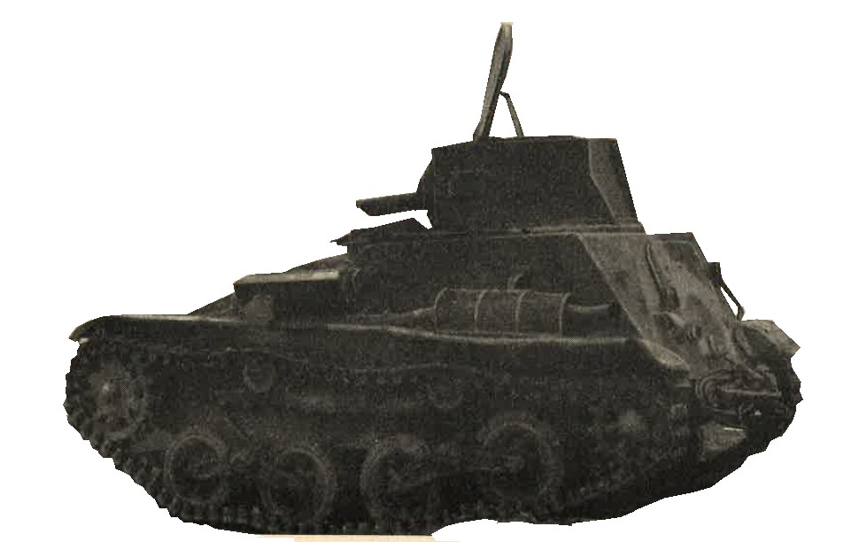
Figure 240. Tankette Model 92.
b. Japanese Tankette model 94 (1934).
This tank embodies the general design of the original tankette (figure 241). The rear idler has been replaced by a trailing ideler, while the drive sprocket has been lowered accordingly. Suspension; bell crank, with armored compression springs. Rubber tired bogie wheels, and two return rollers are used. The engine is reported to be a four cylinder in line Ford tractor motor of 32 horsepower. Steering is the clutch brake principle.
Approximate specifications
|
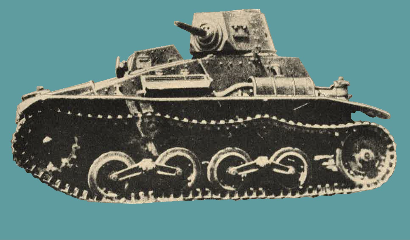
Figure 241. Tankette Model 94 (1934). |
Approximate maximum performance
| 1. | Speed | --------- | 26 miles per hour. |
| 2. | Range of action | --------- | 100 miles (estimates). |
| 3. | Gradient | --------- | 27 degrees (also reprted as 30 degrees. |
| 4. | Obstacles : Trench | --------- | 4 feet 6 inches wide. |
| 5. | Obstacles : Step | --------- | No details. |
| 6. | Obstacles: Ford | --------- | 2 feet deep. |
c. Japanese Tankette model 97 (1937).
Various specifications have been reported for a tank of this size (figure 242). It is not certain if these refer to several different models of teh M2597 or whether they relate to an even later model, the M2598 (1938). The suspension of this tank remains unchanged from that of the M2594 tankette. The hull, however, has been completely redesigned. More room has been provided in the turret to accommodate the 37-mm tank gun. As an alternative, a machine gun sometimes is mounted in place of the 37-mm weapon. Particular attention has been paid to a more simple design of the front plate and improved deflection angles. This tank is powered by a 4 cylinder, in line, air cooled diesel engine of 48 horsepower. Engine specifications indicate, however, thaht this engine would theoretically develop 105 horsepower at 2000 rpm.
Approximate specifications
|
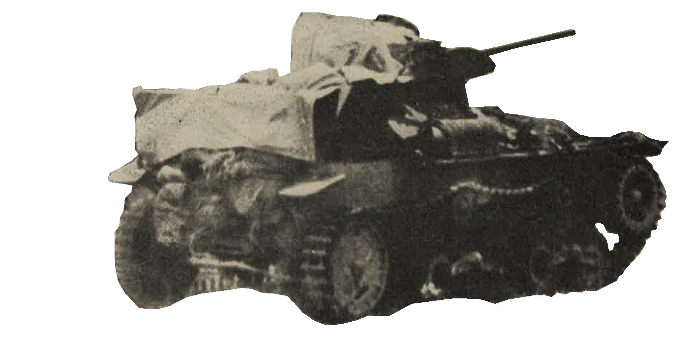
Figure 242. Model 97 (1937) tankette. |
Approximate maximum performance
| 1. | Speed | --------- | 28 miles per hour. |
| 2. | Gradient | --------- | 30 degrees. |
| 3. | Obstacles : Trench | --------- | 5 feet 3 inches wide. |
| 4. | Obstacles: Step | --------- | No details. |
| 5. | Obstacles : Ford | --------- | 2 feet 6 inches deep. |
3. WWII JAPANESE LIGHT TANKS
a. Light tank Model 93 (1933). This tank (figure 243) represents the early development of the light tank series. The box type hull is divided into three compartments. The center portion is the fighting compartment, the superstructure of which overhangs the tracks. The right hand side at the front of the fighting compartment is extended forward to form a sponson for the ball mounted machine gun. The driver sits left, while the hull gunner sits right, in the forward compartment. The 6 cylinder gasoline engine is mounted to the rear of the hull.
The suspension consists of six small, rubber tired bogie wheels mounted on three semielliptic springs on each side. There are three return rollers. Front sprocket drive and center guide track are employed. The turret mounts one machine gun to the front, while some photographs show another mounted in the rear. Traverse 360 degrees.
Approximate specifications
|
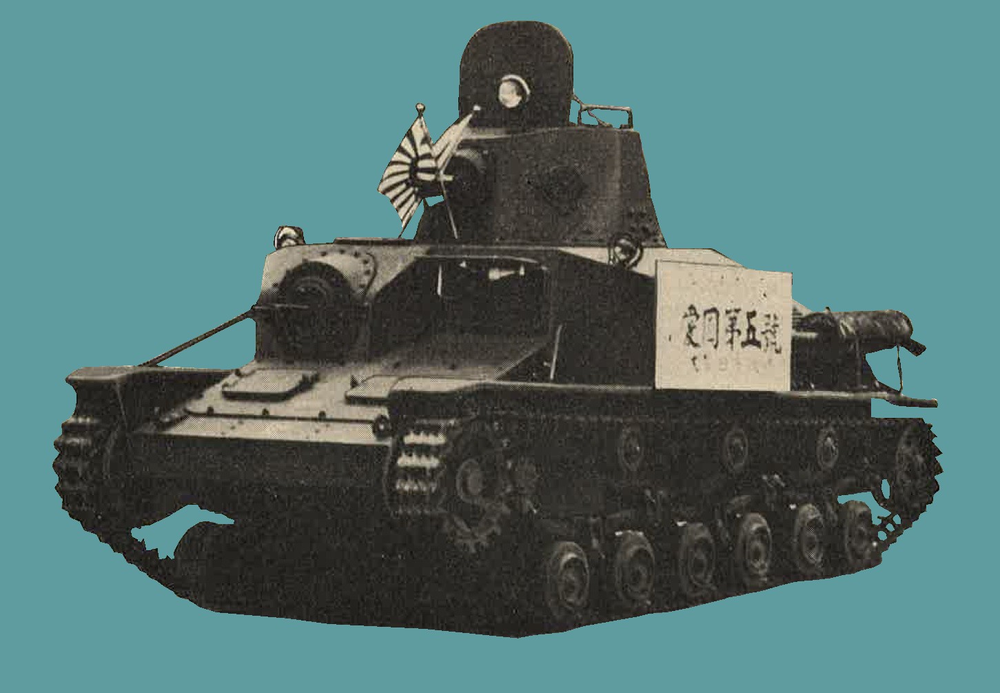
Figure 243. Model 93 (1933) light tank. |
Approximate maximum performance
| 1. | Speed | --------- | 28 miles per hour. |
| 2. | Obstacles: Trench | --------- | 5 feet 8 inches wide. |
| 3. | Obstacles: step | --------- | 1 foot 6 inches high. |
| 4. | Obstacles: Ford | --------- | 2 feet 8 inches deep. |
b. Japanese Light tank Model 93 (1933) improved.
Probably produced in 1933-34, this tank is an improved model of teh M2593 in that the suspension has 4 bogie wheels coupled together in pairs via transverse even lever. It is not clear whether the apex is mounted to the hull by means of a bell crank or a stub shaft. Likewise it is not clear whether the armored compression ring is used at this stage of development. Two return rollers are used, as well as front sprocket drive. The hull of this vehicle is almost identical with that of the previous model.
Approximate specifications
|
Approximate maximum performance
| 1. | Speed | --------- | 28 miles per hour. |
| 2. | Range of action | --------- | 120 miles. |
| 3. | Obstacles: | --------- | 5 feet 8 inches wide. |
| 4. | Obstacles: | --------- | 1 foot 6 inches high. |
| 5. | Obstacles: | --------- | 2 feet 10 inches deep. |
c. Japanese Light tank Model 95 (1935).
In production from 1935 to at least 1942, there is a great deal of evidence to show that Japanese light tank design was frozen in 1935 to produce large numbers of these tanks (figure 244). The hull has been completely redesigned. The suspension has been improved to utilize the bell cranck and armored compression spring. The tank is powered by a 6 cylinder in-line air cooled Diesel engine. The hull is constructed over an angle iron frame, with backing plates at the corners; insulation is provided by layers of woven asbestos. Ammunition for the 37-mm tank gun is carried stored in clips and racks in the fighting compartment.
Two types are known. Model 94 shell - presumably HE of 1934 model, and Model 94 AP shell - presumably APHE of 1934 model. 1170 rounds of 7.7-mm ammunition are stored in magazines just below the hull machine gun. 1800 rounds are carried in the fighting compartment for the turret machine gun.
Specifications from actual examination
|
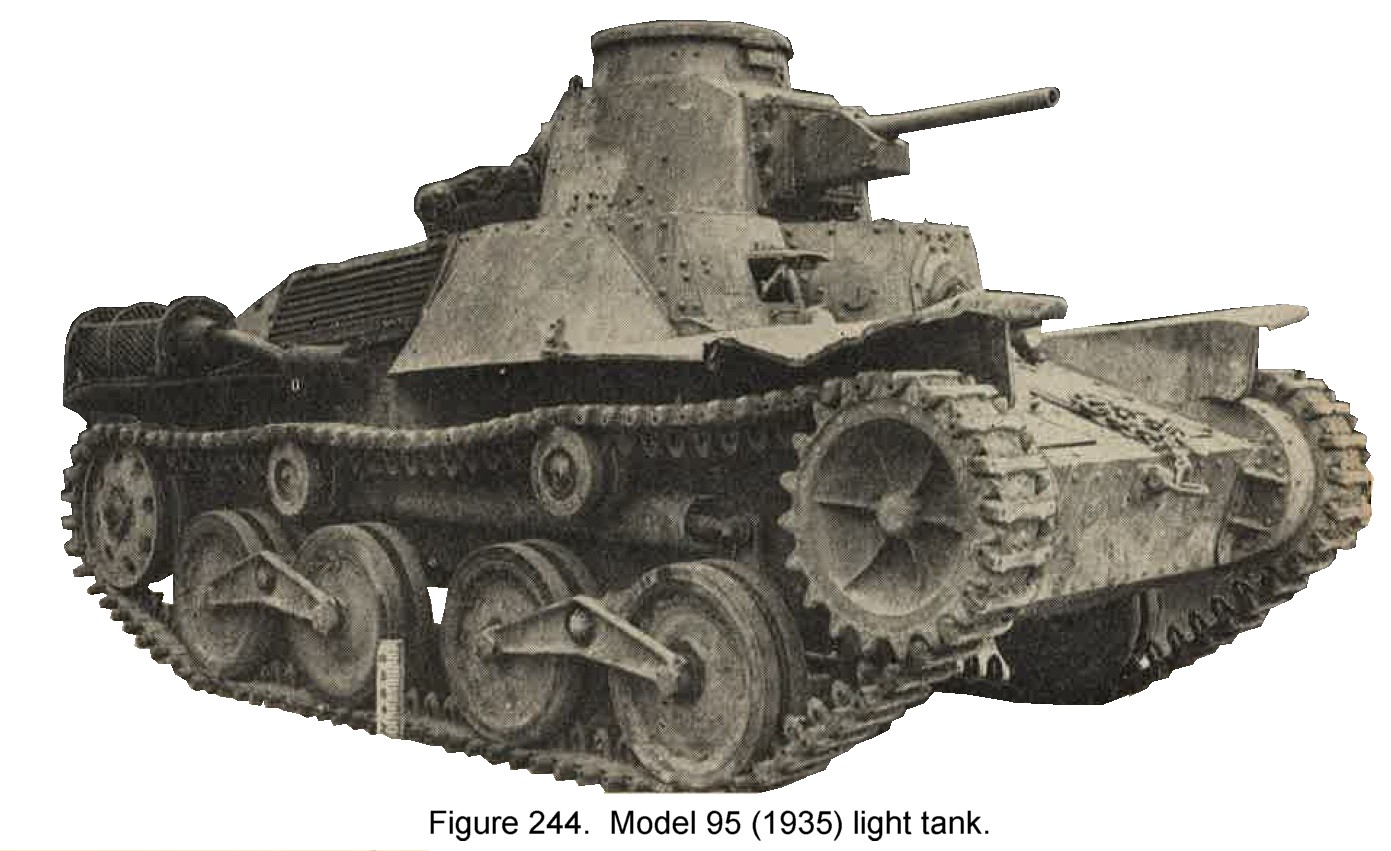 |
Approximate maximum performance
|
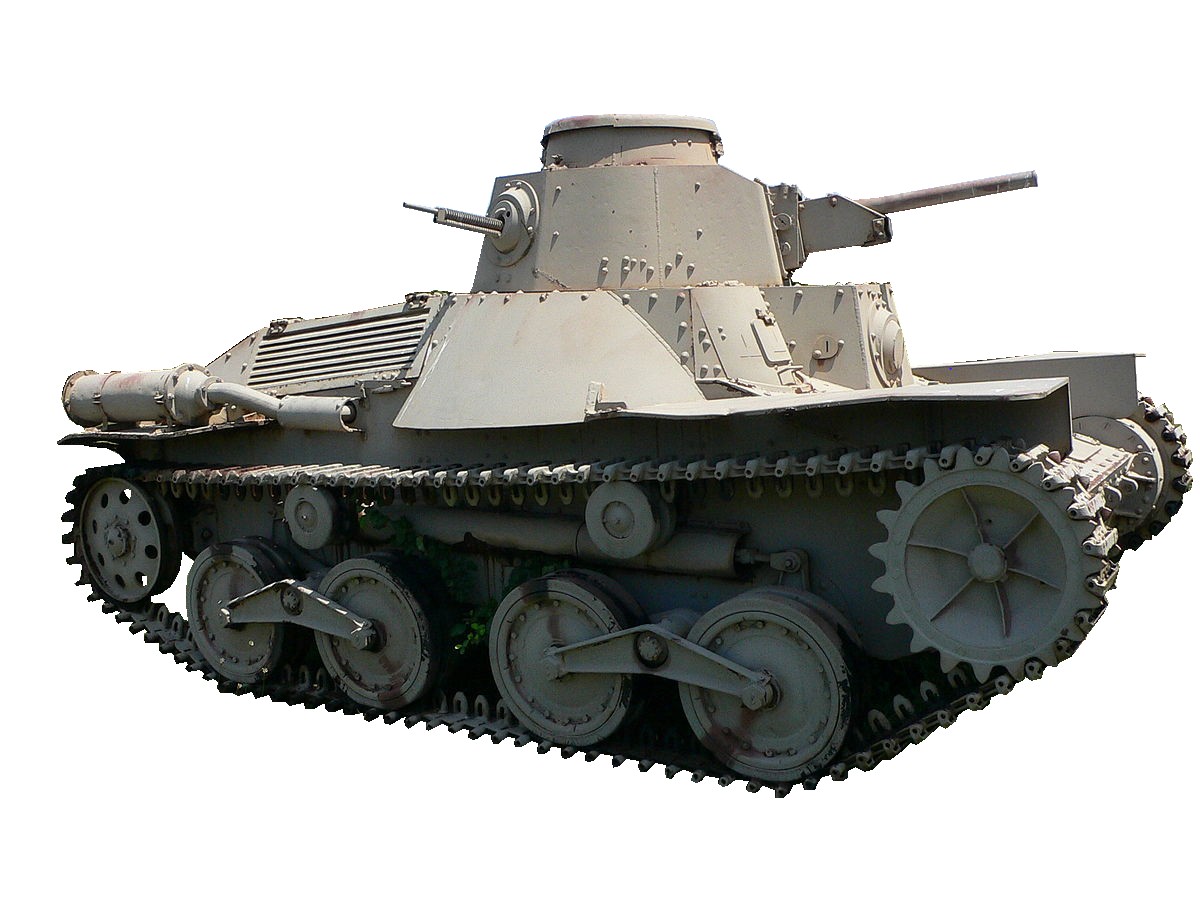 |
d. Japanese Light tank "Keni".
It is considered that this tank is not an obsolete model (as of 1944). It probably has been produced subsequent to the M2595 light tank. The 47-mm gun is a significant feature.
Approximate specifications
|
Approximate maximum performance
|
4. WWII JAPANESE MEDIUM TANKS.
a. Japanese Medium tank Model 89 A (1929).
This tank (figure 245) is characterized by its box type hull, short front plate with door to the right, vertical front plate above this with hull machine gun mounted to the right, and small cupola hinged to top of turret. Five small return rollers are mounted along a girder. There are 9 small bogie wheels. The leading bogie wheel is independently mounted, while protective skirting all but covers the suspension. This tank is rear sprocket driven and powered by a gasoline engine. There is a rear turret machine gun, while the main armament is a 57-mm low velocity gun. Traverse 360 degrees.
|
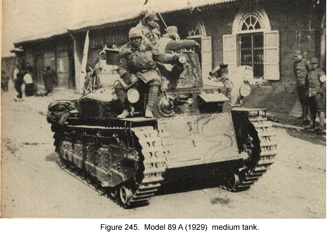 |
| 1. | Speed | --------- | 15 miles per hour. |
| 2. | Range of action | --------- | 100 miles. |
| 3. | Gradient | --------- | 34 degrees. |
| 4. | Obstacles: Trench | --------- | 8 feet 3 inches wide. |
| 5. | Obstacles: Step | --------- | 2 feet 9 inches high. |
| 6. | Obstacles: Ford | --------- | 3 feet 3 inches deep. |
b. Japanese Medium tank Model 89 B (1929).
Also reported as the M2592 (1932), this tank (figure 246) differs from the M89A in that it has a long front which combines with the driver's front plate. The tuurret has been completely redesigned to include a new type of cupola and a more practical aperture for mounting the 57-mm gun. The gasoline ebgine has been replaced by a Diesel engine, but the armament and the armor thickness remain the same.
|
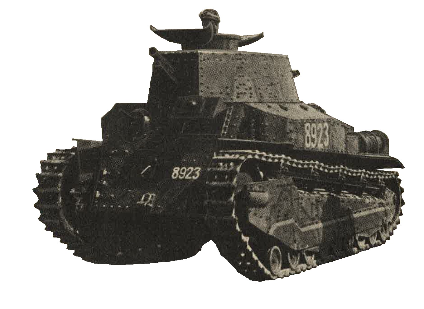
Figure 246. Model 89 B (1929) Medium tank. |
| 1. | Speed | --------- | 15 miles per hour. |
| 2. | Range of action | --------- | 100 miles. |
| 3. | Gradient | --------- | 34 degrees. |
| 4. | Obstacles: trench | --------- | 8 feet 3 inches winde. |
| 5. | Obstacles: Step | --------- | 2 feet 9 inches high. |
| 6. | Obstacles: Ford | --------- | 3 feet 3 inches deep. |
c. Japanese Medium tank Model 84 (1934).
Probabbly produced in 1934 in quantity, this tank (figure 247) has been extensively used in China. Comparison with the M2589 Models A and B shows that the return rollers have been reduced to four, the girder has been removed, and the skirting redesigned. The long front plate has a door on the left, above which is mounted the hull machine gun. The driver sits to the right. The Diesel engine has been increased to 160 break horsepower. With the above exceptions the M 2594 is practically identical with the M2589 B. This tank is often seen with a ditching trail.
|
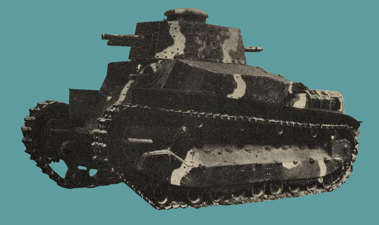
Figure 247. Model 94 (1934) medium tank. |
| 1. | Speed | --------- | 20 miles per hour. |
| 2. | Range of action | --------- | 100 miles. |
| 3. | Gradient | --------- | 34 degrees. |
| 4. | Obatacles: Trench | --------- | 9 feet wide. |
| 5. | Obstacles: Step | --------- | 2 feet 9 inches high. |
| 6. | Obstacles: Ford | --------- | 3 feet 3 inches deep. |
d. Japanese Medium tank Model 97 (1937).
Probably produced in 1937 - 1940. some of the design features of this tank (figure 248) are directly due to lessons learned from tankette and light tank construction. The four central bogie wheels are paired and mounted on bell cranks resisted by armored compression springs. Each end bogie wheel is independently bell crank mounted to the hull in a similar manner. There are three return rollers, the center one carrying the inside half of the track only. Backing plates are used to reinforce hull joints and corners. Numbers of these tanks are known to have been used in Burma. Other specimens were encountered on Guadalcanal.
|
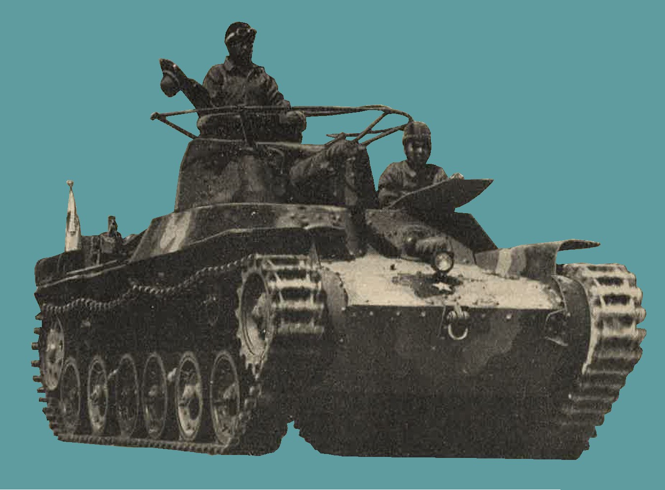
Figure 248. Model 97 (1937) medium tank. |
| 1. | Speed | --------- | 25 miles per hour. |
| 2. | Radius of action | --------- | 100 miles. |
| 3. | Gradient | --------- | 34 degrees. |
| 4. | Obstacles: Trench | --------- | 8 feet 3 inches. |
| 5. | Obstacles: Step | --------- | 2 feet 6 inches high. |
| 6. | Obstacles: Ford | --------- | 3 feet 3 inches deep. |
e. Japanese Medium tank (unidentified).
Probably produced in 1939, this tank is believed to have been employed in Corregidor. Its identity (figure 249) has not been confirmed. With the exception of the turret and main armament, it is basically the same in design as the Model 2597 medium tank. The turret has been improved to accommodate a modern high velocity gun, believed to be of 47-mm caliber. As usual there is a rear turret machine gun. The long overhanging rear portion of the turret would therefore provide more room for the simultaneous firing of both weapons. With the exception of the turret and armament, specifications are believed the same as those for the Model 2597 (1937) medium tank.
5. WWII JAPANESE HEAVY TANKS.
a. As of 1944, little is knwon of Japanese heavy tanks. as far as it can be ascertained, they have been produced only on limited numbers, as those seen have been reported as being clumsy, lightly armored, and of poor performance. In addition, some years prior to the war, a limited number of "heavies" were bought by Japan. The majority of these (including the "Vickers Independant", weight 32 tons) are obsolete.
b. In 1939, the battle of Nomonhan clearly demonstrated the inadequacy ofJapanese tanks. At the conclusion of this conflict considerable reorganization took place within the Japanese Army. It is reasonable to assume, therefore, that the Japan is now in possession of a modern heavy tank.
6. WWII JAPANESE AMPHIBUOUS TANKS.
a. General. Little specific information is available concerning the Japanese development of this type of tank. Similar to the ground tanks, the first amphibians were purchased from foreign countries, a specific instance being the 3 to 4 ton "Vickers amphibious light tank". Several modifications of this are believed to have been produced by the Japanese.
b. Model 2594 (1934) light amphibuous tank. An unconfirmed report indicates the existance of a tank, tentatively identified as the Model 2594 (1934) light amphibious tank, prssessing the following specifications:
| Weight | ------------ | 4 Tons. |
| Length | ------------ | 14 feet 10 inches. |
| Width | ------------ | 7 feet 11 inches. |
| Height | ------------ | 8 feet 10 inches. |
| Armament | ------------ | 1 - 37-mm gun, 1 Machine Gun. |
| Armor | ------------ | Up to 20-mm (0.79 inch). |
It is considered that the armor and armament, coupled with the dimensions, are hardly compatible with a weight of only 4 tons.
c. New type amphibuous tank. The photograph illustrated in figure 250 shows the most modern trend yet encountered in Japanese tank design. No information is available to indicate the model number or date od production. The system of flotation is extremely interesting and is achieved by attachment of a bow and stern pontoon. Pontoons conform to the shape of the hull, and are attached by a series of pincer clamps which are controlled by a handwheel situated inside the tank, enabling their quick release if so desired.
The volumeof the bow pontoon is estimated at 220 cubic feet, and that of the stern pontoon at 106 cubic feet. Two rudders are situated in the stern pontoons and are operated from within the hull. Two propellers are fitted to the rear of the tank. With exceptions of the suspension, this tank is an entirely new Japanese design, the hull being simplified, reentrant angles eliminated, and welding used throughout. IN addition, the round turret is of a new type, characterized by its considerably increased diameter, giving the impression of greatly reduced height.
To prevent water entering rubber seals are fitted around all openings up to and including the turret ring. The tank hull is not divided into individual compartments. Suspension closely ressembles that of the M 2594 and M 2597 takettes, excepting that the compression springs are mounted within the vehicle. No specific details are available. But there are definite indications that the primary armament of this shows improvement. Of particular significance is the coaxial mounting of the turret machine gun.
As no Japanese tank has been encountered in the past with its weapons so mounted, This fact must be regarded as a radical departure in their tank design. The following data has been obtained from a preliminary examination;
| Weight; | |||
| Tank (only) | ---------- | 13 Tons (estimated) | |
| Pontoons (only) | ---------- | 3 Tons(estimated) | |
| Length; | |||
| Tank (only) | ---------- | 15 feet 8 inches. | |
| With pontoons | ---------- | 24 feet 7 inches. | |
| Width | ---------- | ---------- | 9 feet 2 inches. |
| Height | ---------- | ---------- | 7 feet 6 inches. |
| Ground clearance | ---------- | ---------- | 14 inches. |
| Crew | ---------- | ---------- | 5 men. |
| Armor | |||
| Turret - Sides | ---------- | 13.2-mm (0.52 inch). | |
| Turret - Top | ---------- | 6-mm (0.25 inch) | |
| Hull; | |||
| Front | ---------- | 12-mm (0.47 inch). | |
| Sides | ---------- | 9-mm (0.55 inch). | |
| Rear | ---------- | 8-mm (0.32 inch). | |
| Top | ---------- | 6-mm (0.24 inch). | |
| Bottom | ---------- | 8.5-mm (0.334) | |
| Armament | ---------- | ---------- |
1 - 37-mm model 1 (1941) in turret. 1 - 7.7-mm Machine Gun Coaxially mounted. 1 - 7.7-mm Machine Gun in hull forward. |
| Engine | ---------- | ---------- | 6 cylinder air-cooled Diesel (reported to be identical with that in the model 2595 Light tank). |
| Fuel capacity | ---------- | ---------- | 66 gallons (2 tanks). |
| Suspension | ---------- | ---------- | 2 boagies on each side of vehicle. Bogies consist of 2 wheels mounted on a transverse even lever. rear trailing idler serves as an additional bogie. |
| Track | |||
| Length overall | ---------- | 32 feet 1 inch. | |
| Ground contact | ---------- | 11 feet 1 inch. | |
| Width | ---------- | 1 foot. | |
| angle of approach | ---------- | 56 1/4" | |
| Vision apertures and pistol ports | |||
| Hull | ---------- |
1 - 4x1 inch slit for drivers. 1 - 4x1/8 inch slit for hull gunner. 4 pistol ports, one on each quarter of the hull. |
|
| Turret | ---------- |
2 - 3.75 inch diameter vision ports, use on each side of the 37-mm gun. 2 - 4x1/8 inch slits, one on each side of the turret. 3 pistol ports. One at each side and one at the rear. |
|
| Safety glass | ---------- | Shatter proof blocks are are clamped over all vision slits to prevent "bullet splash" or entrance of water. Vision ports are protected by 3-inch safety glass windows. |
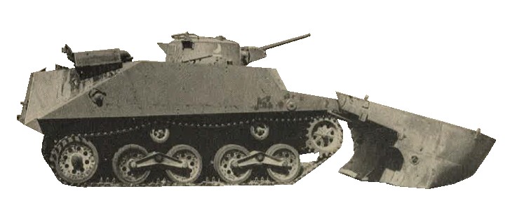
Figure 250. Amphibious tank showing pontons.
7. WWII JAPANESE ARMORED CARS.
a. Japanese Armored car Model 25 (?) "Vickers Crossley".
This armored car (Figure 251) may be classified as obsolete and is readily identified by it hemispherical turret. A small domed cupula, in two hinged halves, surmounts the turret. Traverse 360 degrees, the turret mounts only two machine guns, although there is provision for four. Each of the weapon openings is covered with a small flap, which is closed when the gun is removed. All machine guns are of the Vickers type. Guns are ball mounted and have a limited traverse independant of the turret. The front wheels are single, while the rear wheels are dual. The chasis is believed to be standard commercial type weighing 2.8 tons. In the past, this armored car was incorrectly classified as the "OSAKA" Model 2592 (1932).
APPROXIMATE SPECIFICATIONS
|
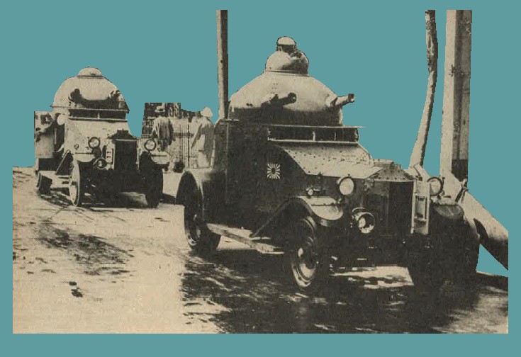
Figure 251. Model 25 (?) "Vickers crossley" armored car. |
b. Japanese Armored car Model 92 (1932) naval type.
This vehicle was likely produced in 1932. The insignia indicates that it (figure 252) is a naval vehicle. In addition to the machine gun in the front and rear, one is mounted on each side of the hull. One is also mounted in the turret. Semielliptic springs provide the suspension for the 6 disc wheel chassis. Wheels are fitted with pneumatic tires. To prevent bellying, when crossing rough terrain, auxiliary wheels are mounted on the frame to the rear of the front wheels.
The radiator is provided with armored shutters. Reconnaissance and guard duties constitute the chief role for this vehicle.
APPROXIMATE SPECIFICATIONS
|
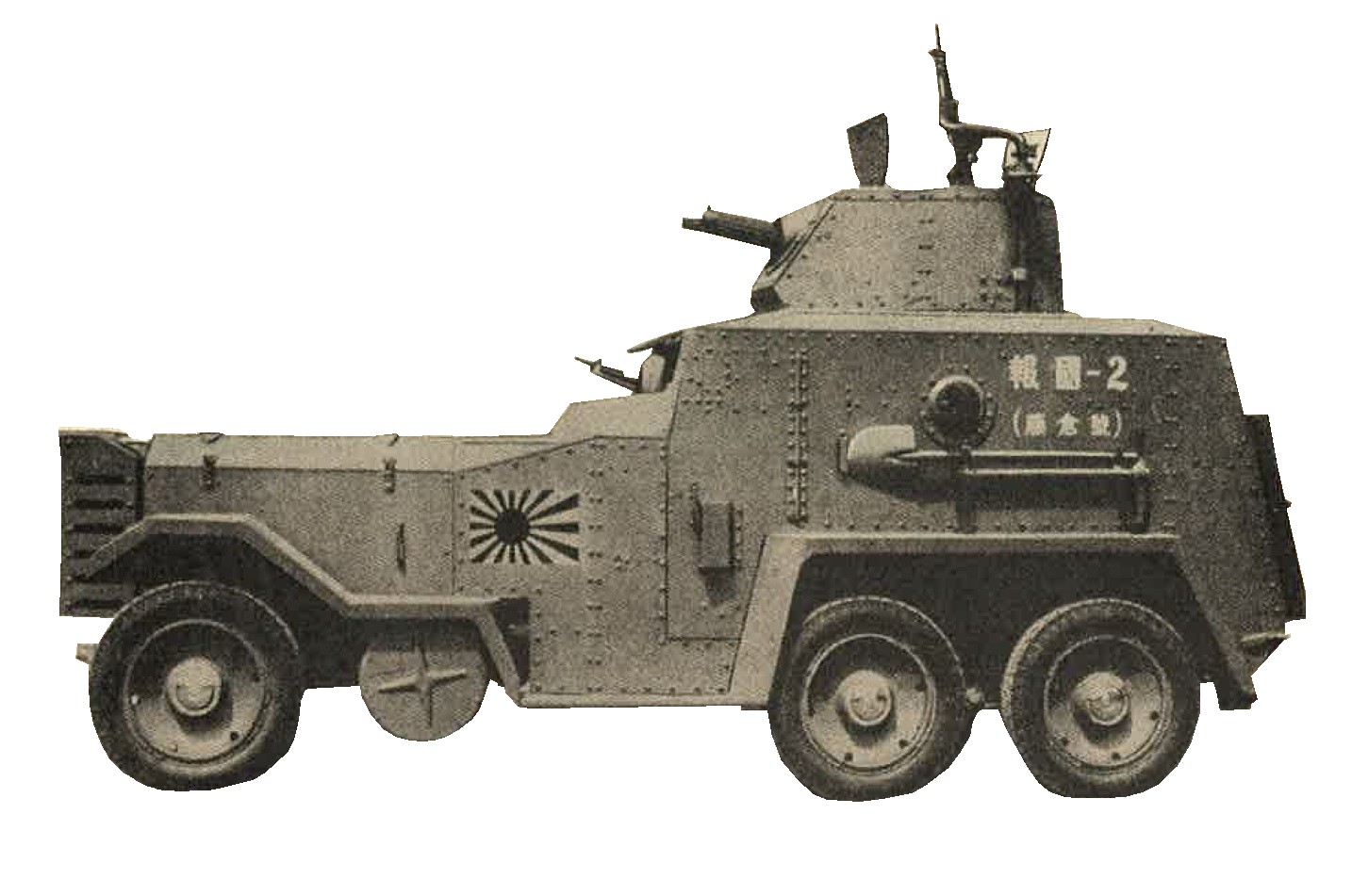
Figure 252. Model 92 (1932) naval type armored car. |
APPROXIMATE MAXIMUM PERFORMANCE
| Speed | ---------- | 50 miles per hour |
c. Japanese Armored car Model 92 (1932) "OSAKA".
Until recently (1944), considerable confusio has existed between this armored car and the model 25(?) "Vickers Crossley", specifications of the "Osaka" being attributed to the later vehicle. While no details are available, it is believed that the "Osaka" is of Japanese origin, a standard commercial chassis being used for its manufacture. Wheels are fitted with pneumatic tires. The front single and the rear dual mounted. Machine guns are of the Vickers type; One is mounted in the front of the turret.As an extensive free traverse has been allowed to this gun, it is considered possible that the turret is fixed and cannot be traversed. As the design of the driver's front plate gives no indication that the second machine gun is mounted in the front of the hull, it is probable that this weapon is mounted at the rear of the vehicle.
APPROXIMATE SPECIFICATIONS
| Weight | ---------- | 6.4 ton. |
| Length | ---------- | 16 feet 5 inches |
| Width | ---------- | 6 feet |
| Heght | ---------- | 8 feet 8 inches |
| Ground clearance | ---------- | 11 inches |
| Crew | ---------- | 4 to 5 men |
| Armament | ---------- | 2 MG's |
| Armor | ---------- | 8 to 11 mm (0.32 to 0.43 inches) |
| Engine | ---------- | 4 cylinders, 35 horse power. |
| Fuel | ---------- | Gasoline. |
| Cooling | ---------- | Water |
APPROXIMATE MAXIMUM PERFORMANCE
| Speed | ---------- | 37 miles per hour |
| Range of action | ---------- | 150 miles |
d. Japanese Armored car Model 1933 (Sumida).
This vehicle (figure 253) has been used extensively in China and was specially designed to run either on railway lines or hard roads. To effect the change from rails to road, the vehicle is raised up by 4 built in jacks. solid rubber tires then are placed over the 6 flanged steel wheels, and the vehicle can be driven off the rails onto the road. This operation is said to take 10 minutes. When traveling on rails, 3 solid rubber tires are attached on each side of the hull.
APPROXIMATE SPECIFICATIONS
|
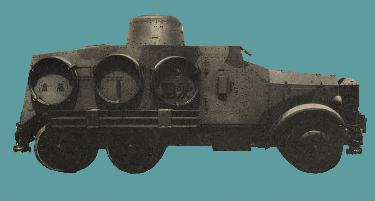
Figure 253. Model 93 (1933) "Sumida" armored car. |
APPROXIMATE MAXIMUM PERFORMANCE
| Speed on rails | ---------- | 37 miles per hour. |
| Speed on road | ---------- | 25 miles per hour. |
8. ARMAMENT OF JAPANESE WWII ARMORED UNITS.
The following weapons are known to be used in Japanese tanks and armored cars:
a. Japanese Model 91 (1931) 6.5-mm MG.
This weapon (figure 254) is merely the infantry machine gun, Model 11 (1922) adapted to tank requirements by the removal of the bipod. It is considered possible that it has now been replaced largely by the better designed and heavier calibered Model 97 (1937) 7.7-mm machine gun. For detailed characteristics of th Model 11, see Chapter 9, Sec. II.
b. Japanese Model 97 (1937) 7.7-mm MG.
This is the standard machine gun (figure 255) at present used by Japanese tanks. A sholder controlled weapon, it is fitted with conventional sights. It may readily be identified by the specially designed modified stock. When used for tank purposes, a fixed focus telescopic sight of 1 1/2 power x 30 degrees field of view is usually fitted. To prevent injury to the gunner, a heavy rubber eye pad is attached to the rear of the scope. By the addition of a bipod, this weapon may be converted to ground purposes.
CHARACTERISTICS
| Caliber | ---------- | 7.7-mm (.303 inch) |
| Principle of operation | ---------- | Gas operated, full automatic only. |
| Type of feed | ---------- | Vertical box |
| Magazine capacity | ---------- | 30 rounds |
| Length of barrel | ---------- | 28 inches |
| Overall length | ---------- | 46 inches |
| Weight | ---------- | 34 pounds |
| Cyclic rate of fire | ---------- | 500 rounds per minute. |
| Ammunition | ---------- | Fires special model 99 rimless. |
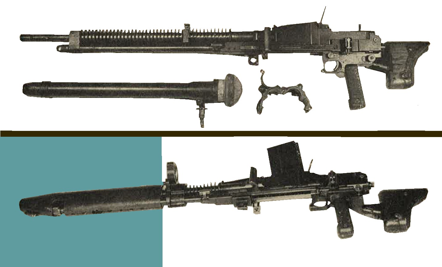
Figure 255. Model 97 (1937) 7.7-mm tank machine gun. (The lower figur eillustrates the armor shield normally used when this machine gun is mounted in a tank). |
Figure 255-a. 7.7-mm ammunition. |
c. Japanese Model 94 (1934) 37-mm tank gun.
Although bearing the same type number as the field piece of similar caliber, these two weapons must in no way be confused, for each has been designed for its own specific purpose. In addition, ammunition is not interchangeable, as the chamber of the tank gun (figure 256) is considerably smaller than that of the antitank gun. The gun appears to constitute the primary armament of Japanese light tanks. In addition, there is evidence that one model of tankette is similarly equipped. It is considered that this weapon has neither the performance nor armor piercing qualities of the U.S. 37-mm tank gun. Mounted in turret, the Japanese weapon is carried by two sets of trunnions, one set allowing the gun a limited "free" traverse, while the other permits the gun to be elevated or depresses.
Traverse and elevation/depression are manually appliedby means of an adjustable shoulder rest attached to the left side of the cradle. The main traverse is obtained by rotating the turret. Telescopic sight, pistol type grip, and trigger are mounted to the left of the gun.
CHARACTERISTICS
| Caliber | ---------- | 37-mm (1.46 inch). |
| Muzzle velocity | ---------- | 2,100 feet per second (estimated) |
| Maximum elevation | ---------- | +24 degrees |
| Maximum depression | ---------- | -20 degrees |
| Traverse | ---------- | 10 degree right, 10 degree left, without rotating the turret. |
| Breech mechanism | ---------- | Vertical sliding, semiautomatic in action |
| Recoil system | ---------- | Hydrospring |
| Ammunition | ---------- | APHE and HE |
Figure 256. Model 94 (1934) 37-mm tank gun.
d. Japanese Model 1 (1941) 37-mm tank gun.
This gun has been recovered but detailed examination has not yet been made (as of 1944). However, from the length of the barrel and the size of the chamber, a muzzle velocity much higher than that of Model 94 (1934) 37-mm tank gun may be expected, and it is believed that this gun will have good armor piecing qualities.
e. Japanese Model 97 (1937) 57-mm tank gun.
It is believed that this weapon (figure 257) is the standard heavy armamnent of Japanese medium tanks. The gun is mounted in the turret and is manually controlled. Elevation and depression are free. The weapon may be traversed also approximately 10 degrees to the left and right, independently of the turret.
Although several specimens have been captured, the condition of the guns have prevented a detailed examination. Sufficient information is available , however, to indicate that it is a short barreled , medium velocity weapon that would be more suitable for employment against ground troops. This would appear to conform to the Japanese past policy of using mainly tanks for the close support of infantry, rather than for tank vs. tank action.
No information is available to indicate id=f this policy is still being adhered to, or whether the future trend will be to substitute a high velocity weapon similar to the Model 1 (1941) 47-mm antitank gun (for characteristics see chapter 9, sec II).
CHARACTERISTICS
| Caliber | ---------- | 57-mm (2.24 inches) |
| Weight | ---------- | 283 pounds. |
| Length of tube | ---------- | 3 feet 1.6 inches |
| Length of chamber | ---------- | 5.1 inches. |
| Number of lands and grooves | ---------- | 20. |
| Maximum length of recoil | ---------- | 11 inches. |
| Maximum elevation | ---------- | +45 degrees. |
| Traverse | ---------- | 10 degrees right, 10 degrees left without rotating the turret. |
| Type of breechblock | ---------- | Vertical sliding. |
| Ammunition | ---------- | only high explosive rounds have been recovered to date (1944). They are characterized by a rather short cartridge case. |
Figure 257. Model 97 (1937) 57-mm tank gun (showing its appearance from outside the turret).
f. Japanese Model 90 (1930) 57-mm tank gun. No information is available as of 1944 concernign this wepon. Photogrpahs of early Japanese tanks suggest that this gun is a short barreled piece resembling the Model 97. It is probable tha the Model 90 was the forerunner of the latter weapon.
g. Japanese 47-mm tank gun.
While no details are available, indications are that the Japanese are now mounting a 47-mm gun in their medium tanks. It is also reported that a model of the light tank is mounting a weapon of this caliber. It is reasonable to assume that this gun is a modern, high velocity antitank piece, in all probability, a modified form of the Model 1 (1941) gun adapted to tank purposes. For characteristics of the Model 1 (1941) 47-mm antitank gun, see section II, chapter 9.
SECTION V - WWII JAPANESE CHEMICAL WARFARE (PART 1).
1. WWII JAPANESE GAS MASKS
a. General. All the known models of gas masks used by Japanese military forces are of the air hose and separate canister type. Rubber stoppers are provided to permit sealing of the canister when it is in use to protect the contents against moisture. IN general the Japanese gas masks afford good protection against the common types of war gases; their facepieces, however, are uncomfortable when fitted to the average occidental face. The American canisters can be ftted to these masks for better protection aganist hydrocyanic acid (AC) and cyanogen chloride (CC) gas than the Japanese canister gives. The existence of horse gas masks of the damp mask type has been reported.
b. Japanese Army gas mask "Model 95".
It has a Khaki stockinette covered facepiece (figure 258) with molded tissot tube and circular eyepieces with removable threaded rims. The eyepieces ae made of glass. A total of 6 elastic straps secure the mask to the head. The Khaki colored canister is approximately 6 inches high, 5 inches wide and 2 3/4 inches thick. The carrier is a rectangular canvas bag. A rubberized hood is sometimes attached to this mask to protect head and shoulders.
Figure 258. Army gas mask Model 95. |
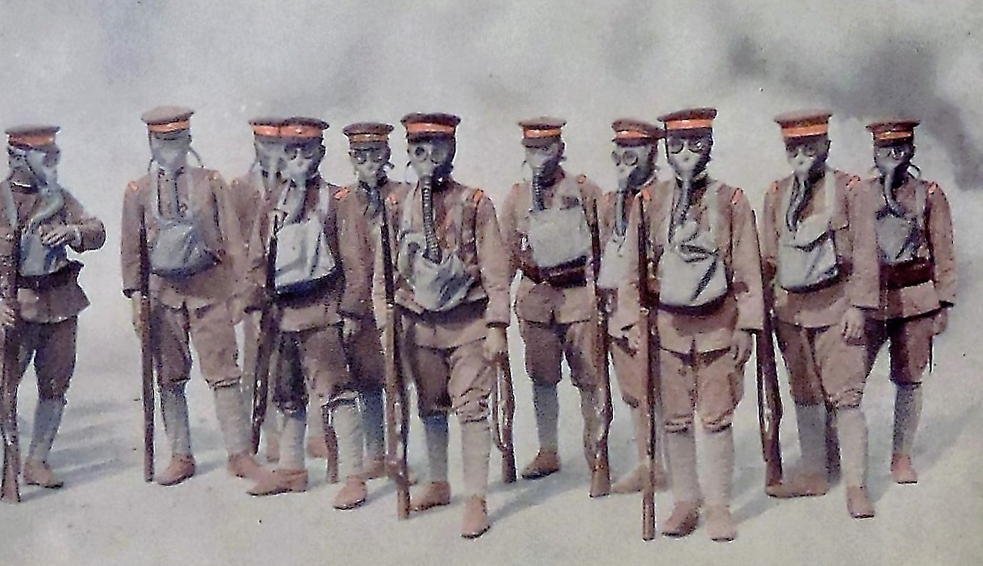
Figure 258-a. Postcard of WWII Japanese soldiers wearing gas masks. |
c. Japanese Army gas mask "Model 99".
Similar in appearance to the "Model 95" (figure 259), the gas mask is fitted with a rubber nosepiece held inside the facepiece by a stud, and has a short canister only about 4 1/2 inches high.
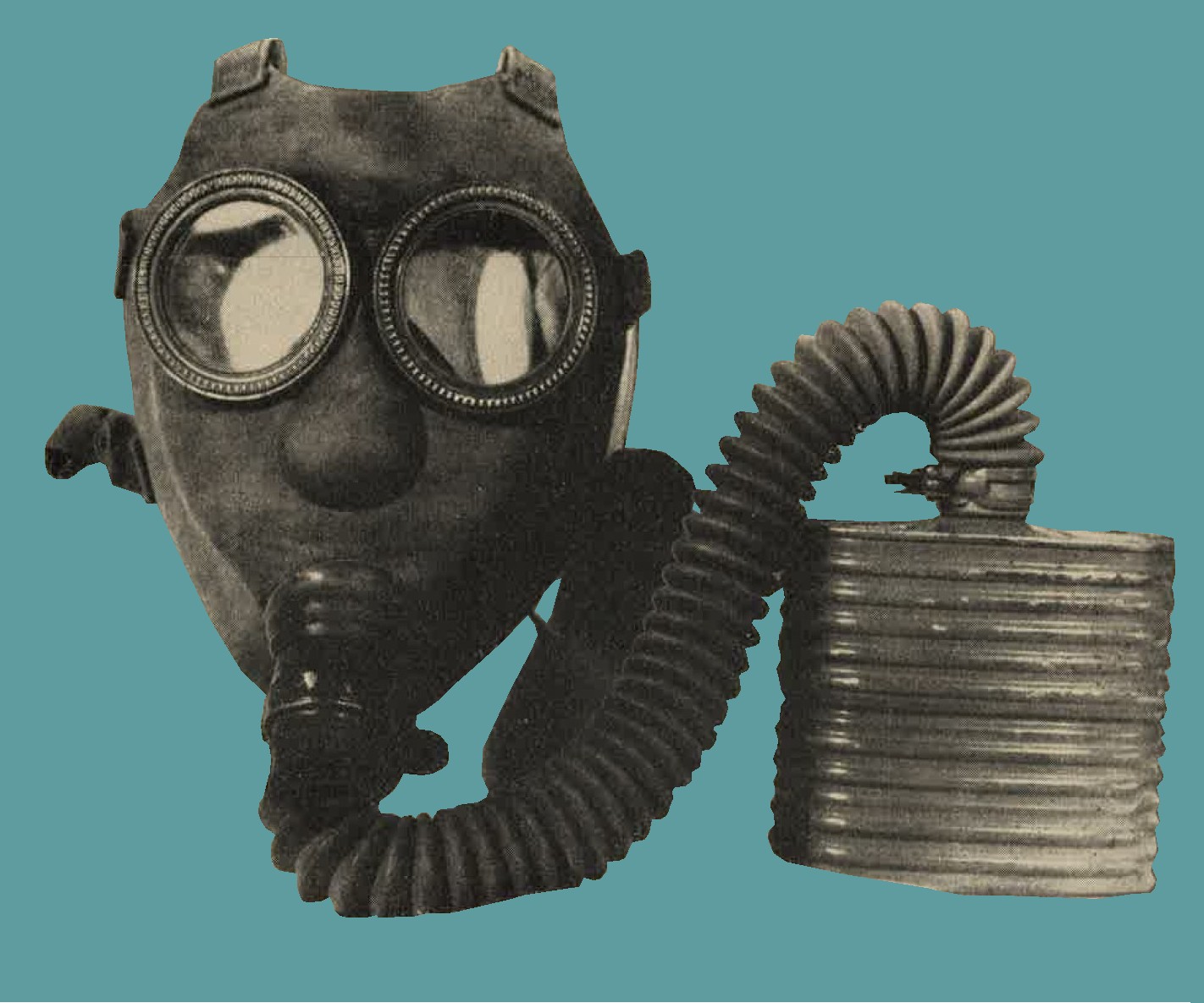
Figure 259. Army gas mask "Model 99". |
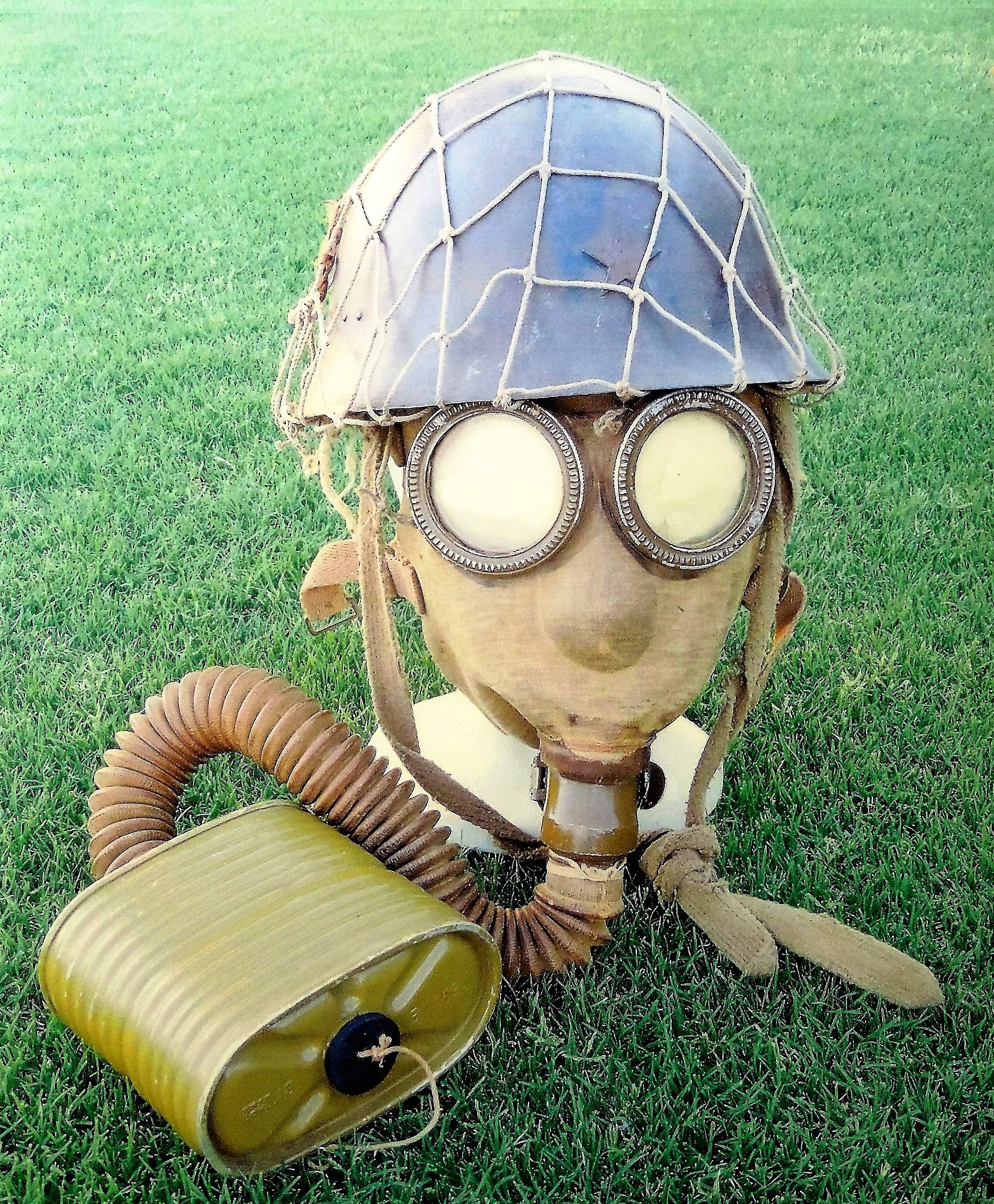
Figure 259-a. Type 99 army gas mask with helmet. Manufactured by Fujikura. 1944. |
d. Japanese Civilian gas mask type 1, Model A (improved).
This gas mask (figure 260), although originally designed for civilian use, also is issued to Army personnel. The facepiece is tan colored with molded tissot tube and circular, glass, eyepieces with fixed rims. The tan colored canister is approximately 4 3/4 inches high, 5 1/4 inches wide and 2 3/4 inches thick. The carrier is a small rectangular canvas bag with a 1 1/2 inch diameter hole in the bottom.
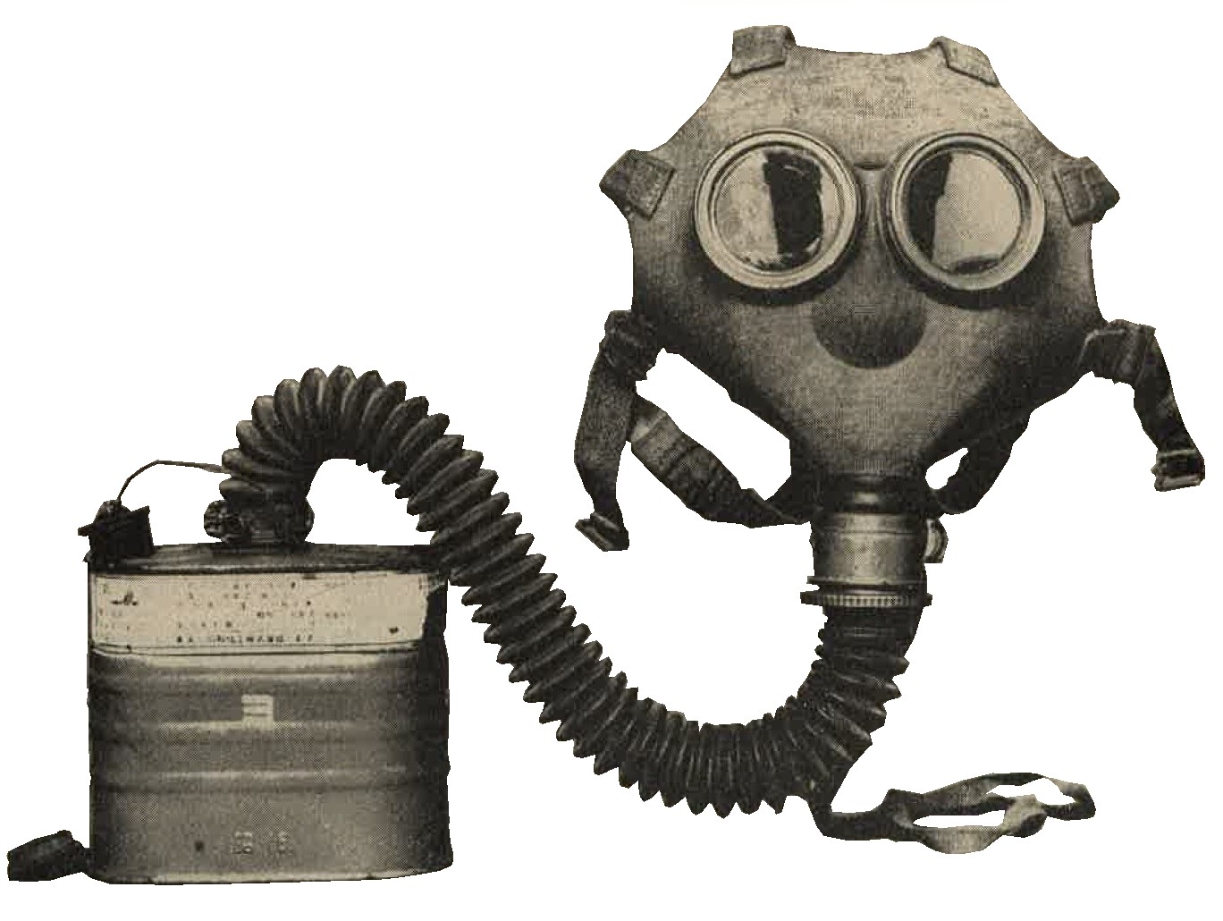
Figure 260. Civilian gas mask Type I, Model A (Improved). |
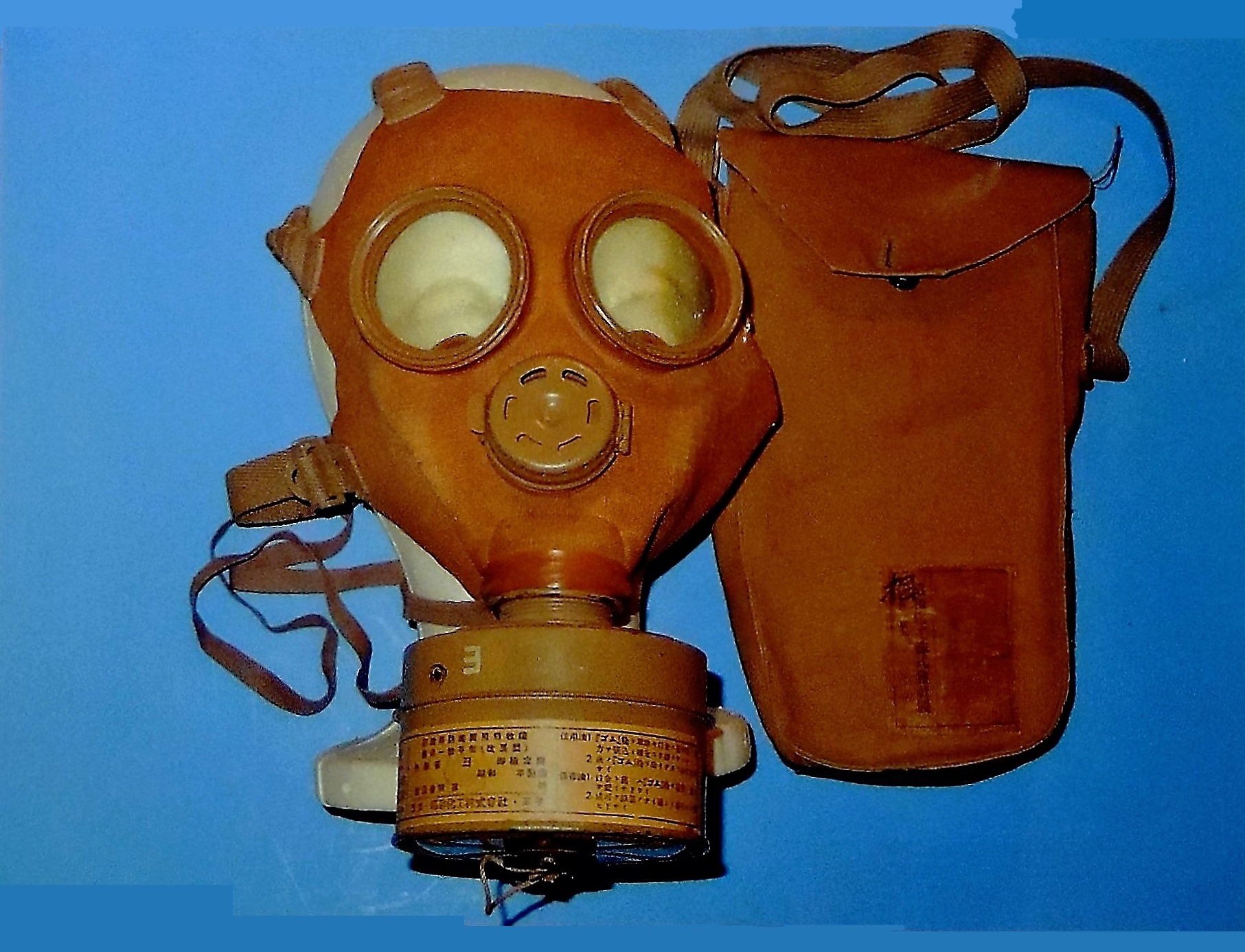
Figure 260-a. Civilian gas mask with carrying case. |
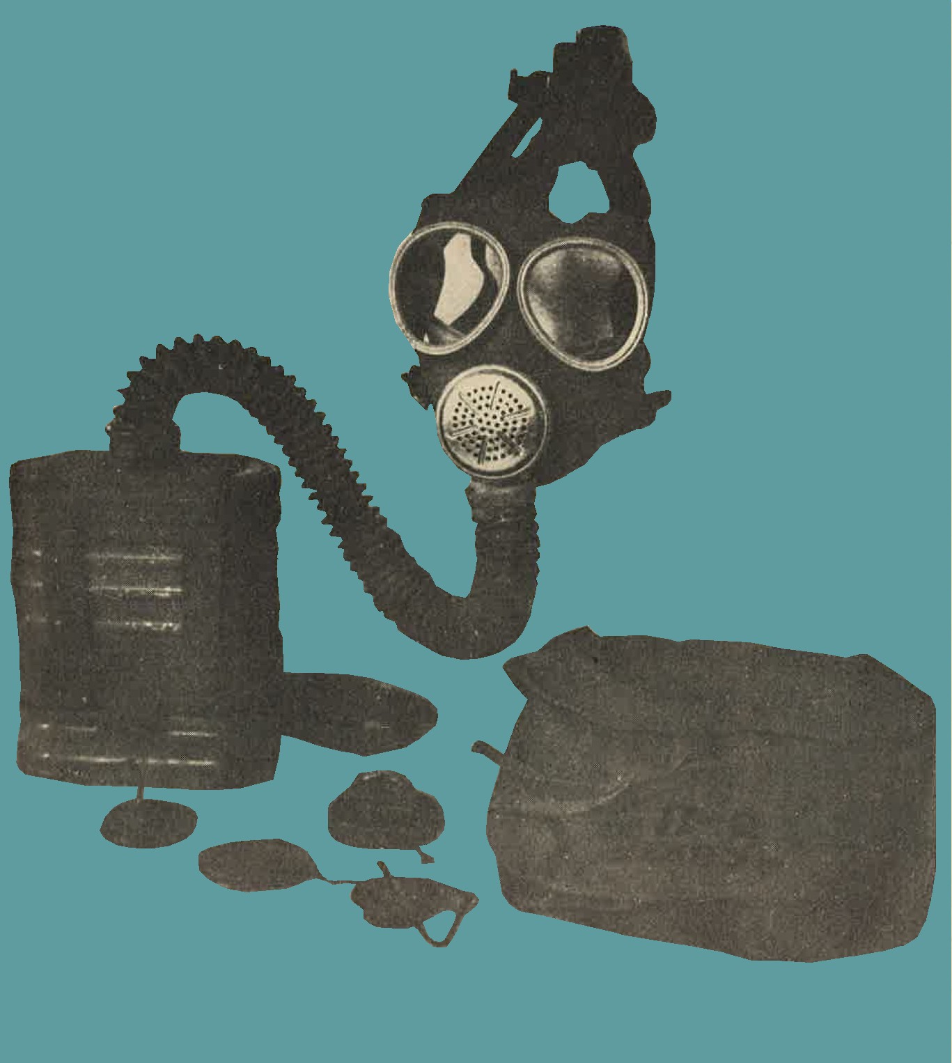
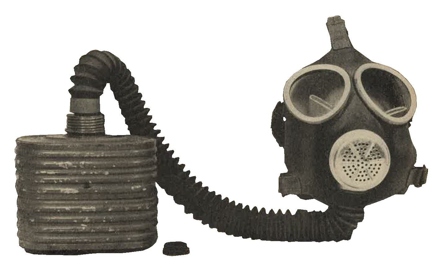
Figure 262. Navy gas mask Model 93, No. 3. |
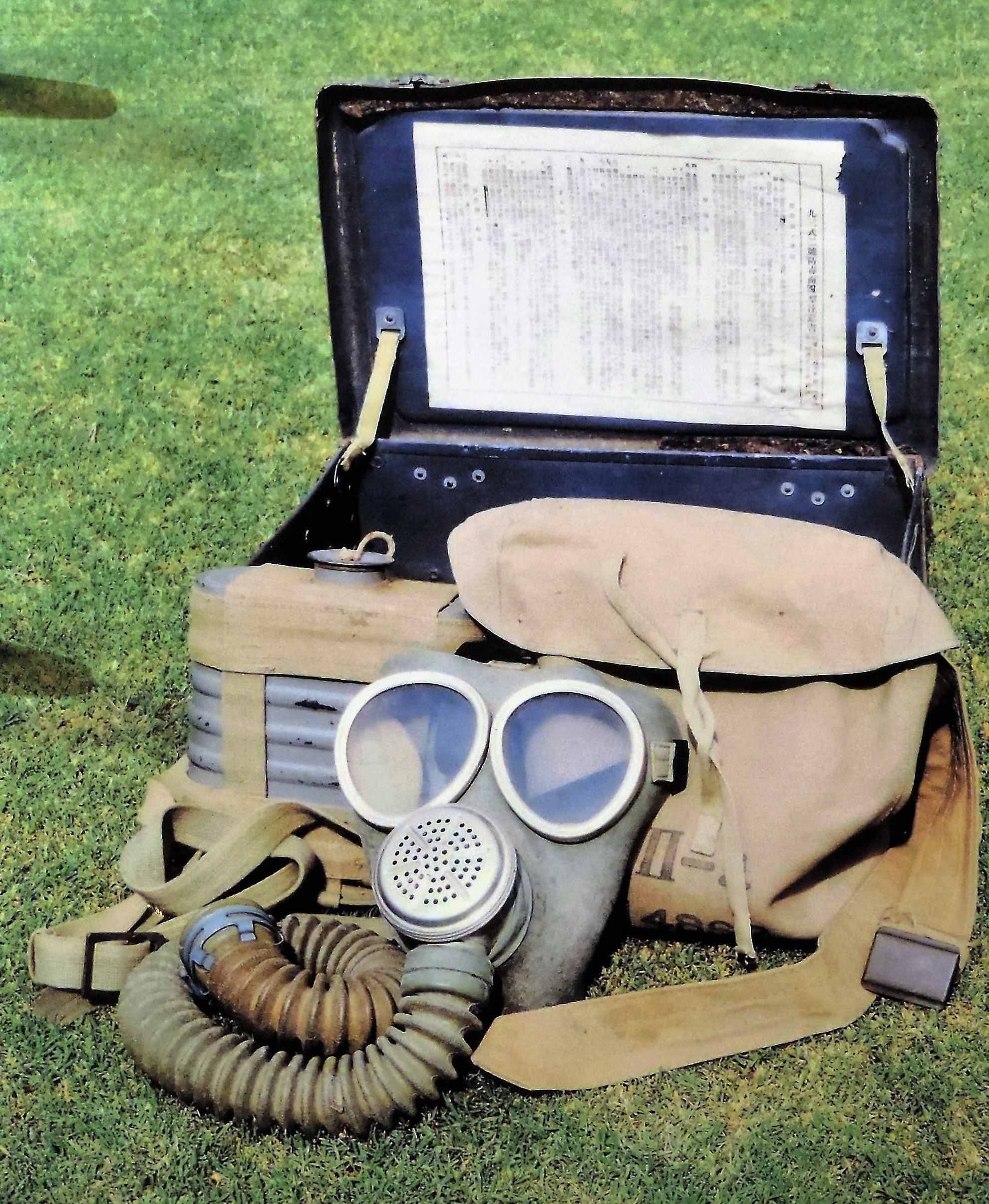
Figure 262-a. Navy gas mask Model 93 with all accessories. |
The color photograph shows the entire ensemble wich includes; The mask itself. Rubber body with glass lenses. Complete with the filter. All painted battleship gray. The canvas carrying bag which is worn by the soldier in the field. Also included is the metal transport box. This box remained on the ship and kept the gas mask protected during travel.
2. WWII JAPANESE GAS MASK ACCESSORIES.
The carriers of most army gas masks are provided with a packet of antifog discs (Figure 263), a container for antifreeze liquid (Figure 264), a hinged metal clamp for closing the air hose, and a cleaning rag. In addition...
FIX BREAK IN PAGE
b. Bleaching powder pouch. The pouch (Figure 270), measuring approximately 12 inches by 7 inches, is made of rubberized fabric and is provided with a tie string, carrying strap, and a pocket containing several pieces of cotton gauze. The pouch holds approximately 5 ounces of bleaching powder, presumably for use in decontamination of articles of individual equipment.
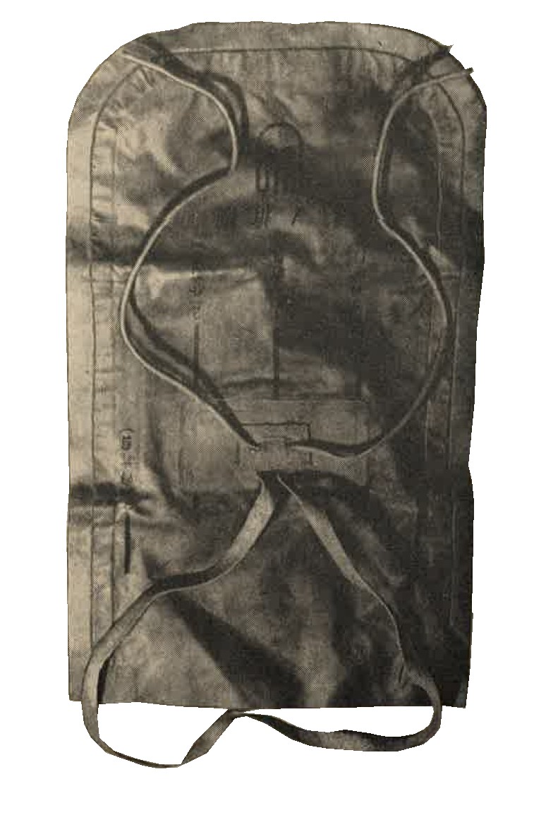
Figure 270. WWII Japanese army bleaching powder pouch.
c. Decontamination agent, No 1. A cylindrical sheet metal container, 2 1/2 inches high and 2 1/2 inches diameter, with one blue band around the casing (figure 271) contains approximately 0.33 pounds crystalline potassium permanganate.
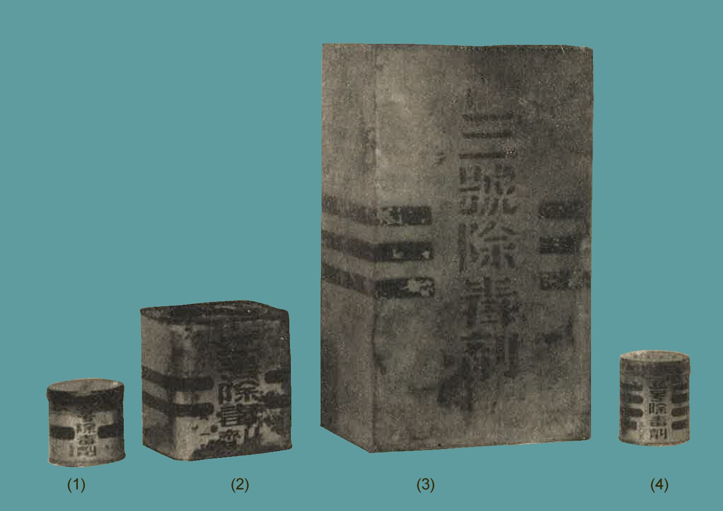
Figure 271. Decontaminating agents (1) No1. (2) No2. (3) No3. (4) No4.
d. Decontamination agent, No 2. A rectangular sheet metal box, 4 1/2 inches high and 4 3/16 inches square (see above figure 271) with two blue bands around the casing, contains approximately 2.25 pounds of flaked sodium hydroxide.
e. Decontamination agent, No 3. A rectangular sheet metal box, 13 1/4 inches high, 7 3/4 inches wide and 5 3/4 inches thick, with three green bands around the casing (see above figure 271) contains approximately 15 pounds of chloride of lime.
f. Decontamination agent, No 4. A cylindrical sheet of metal can, 2 3/4 inches high, 2 7/16 inches in diameter, with four blue bands around the casing (see above figure 271) contains a spherical glass ampule wrapped in cotton gauze. The ampule holds approximately 1.8 ounces of a yellow liquid consisting of a 20 percent solution of chlorine in carbon tetrachloride.
g. Uses. These decontamination agents are used as follows:
| AGENT | FUNCTION |
| No. 1 and No. 2. | For decontamination of tear gases and vomiting gases. |
| No. 3. | For decontamination of blister gases. Used to refill the pouch. |
| No. 4. | For decontamination of blister and vomiting gases. |
The effectiveness of these agents is not known, but is considered comparable with similar Allied agents.
5. WWII JAPANESE GAS DETECTORS.
a. Blister gas detection satchel. The square satchel, 6 inches x 6 inches, with a carrying strap, contains detector papers, a small box of calcium hypochlorite, a box containing 16 glass ampulets of detector material, and a supply of small flags for marking contaminated areas. The white detector material contained in the ampules turns red in contact with blister gases.
b. gas detector kit. The kit (figure 272) comprises a light metal cylindrical barrel, 10 1/4 inches long and 2 1/2 inches in diameter; a rubber bulb and tubbing; and a set of five detector tubes. When testing for war gases the five detector tubes are placed inside the barrel and held in the holes of a rubber stopper provided for this purpose. Air is then drawn through the tubes by means of the rubber bulb. The kit is contained in a wooden carrying case.
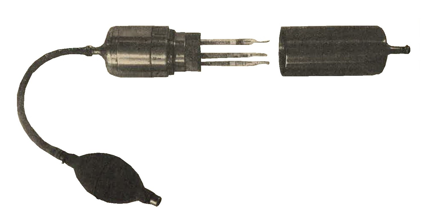
Figure 272. Gas detector.
c. Gas detector kit (Navy model). The kit (figure 273) comprises a rubber, bulb-actuated, metal air pump and set of three detector tubes. Air is drawn through the detector tubes. It is said that the presence of blister gases, and carbon monoxide can be determined by color changes of the indicator materials contained in the detector tubes. The kit is carried in a grey metal case.
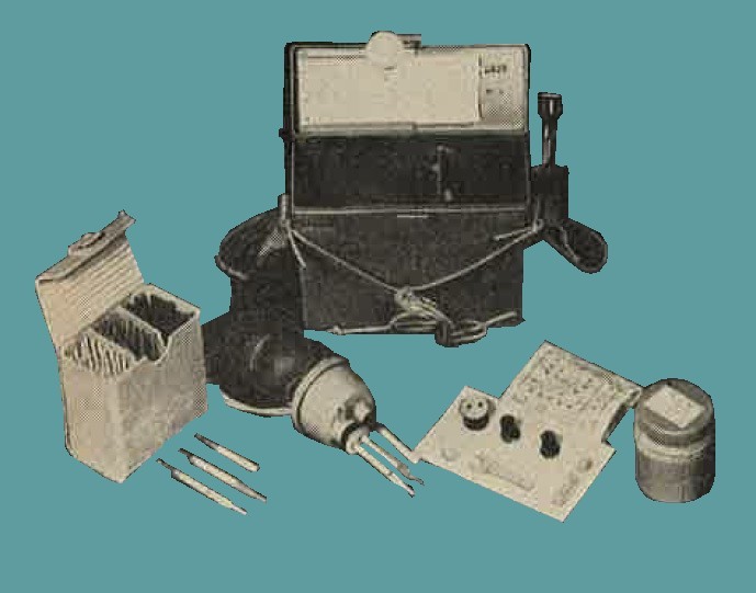
Figure 273. Navy model gas detector kit.
SECTION V - WWII JAPANESE CHEMICAL WARFARE (PART 2).
OFFENSIVE EQUIPMENT.
1. WWII JAPANESE MARKING OF CHEMICAL MUNITIONS.
Indications are that the Japanese attention to war gases has been confined largely to the well known blister, tear, vomiting, etc., gases. In addition, agents for the production of screening smokes are manufactured. The Japanese distinguish between ordinary smoke and toxic, ot tear, clouds by referring to the latter as "special smoke". The type of agent contained in a chemical munition is usually identified by a color band according to the following scheme:
| GAS TYPE | COLOR BAND |
| Choking gases | Blue |
| Tear gases | Green |
| Blister gases | Yellow |
| Vomiting gases | Red |
| Blood and nerve poisons | Brown |
| Screening smoke | White |
Chemical projectiles and most chemical aerial bombs are generally grey in color. Filled shells have a red hand at the nose, followed by a blue band to indicate special handling because of the chemical filling. According to the best evidence available, the type of war gas filling is indicated by a colored band in accordance with the above scheme. This band is about twice as wide as any other band on the shell. A narrow yellow band is believed to indicate a HE burster change, while a white band indicates that the projectile is constructed of steel.
2. WWII JAPANESE GAS SHELLS AND BOMBS.
a. General.
The 90-mm mortar and the 81-mm mortar are believed to have chemical munitions, as is a reported 150-mm mortar, but shells containing these fillings have not been captured. Likewise, the 105-mm gun and 150-mm howitzer shells probably have a chemical filling. The following shells and bomb are definetely known to be filled with war gases,
b. Japanese 50 kg aerial gas bomb.
Overall length 45 inches, body diameter 7.5 inches. Total weight 110 pounds, filling 50:50 lewsite mustard mixture, gray colored with one yellow and one white band between nose and lug and one yellow band between tail and lug.
c. Japanese 75-mm blister gas shell.
Weight 12.5 pounds. Filling 1.4 pounds 50:50 lewsite mustard mixture. Markings; red band followed by blue band (indicating CW filling) on nose, one white and one wide yellow band on body, which indicates blister gas filling.
d. Japanese 75-mm vomiting gas shell.
Weight 13.25 pounds. Filling 0.4 pounds diphenylcyanarsine. Markings, red band followed by blue band on nose. Yellow band below burrelet indicating HE filling, then a wide red band indicating vomiting gas and finally a white band indicating a steel shell.
3. WWII JAPANESE FRANGIBLE HYDROCYANIC ACID (AC) GRENADES.
See Section II, Chapter 9, for description.
4. WWII JAPANESE GAS CANDLES.
Most Japanese gas and smoke candles of the stationary or hand thrown type are fired by means of a matchhead fuze and scratcher block. All Japanese self projecting gas and smoke candles (Figures 274, 275, 276, and table) are composed of an outer container equipped with a
|
|
Figure 275. Medium vomiting gas candle.
Tear gas candle table
| Num | Description | Length | Diameter | Body color | Markings | Weight (Lbs) | Filling | Notes |
| 1 | Tear gas candle | 7.2 | 2.2 | Grey | Green band | 0.5 | CN mixture | Main filling nitrocellulose wafers containing CN. |
| 2 | Small tear gas candle | 5.5 | 2.5 | do | do | .4 | do | Believed to be obsolete. |
Vomiting gas candle table
| Num | Description | Length | Diameter | Body color | Markings | Weight (Lbs) | Filling | Notes |
| 1 | Light vomiting gas candle. | 7.2 | 2.2 | Grey | Red band | 0.6 | DC | Metal ring handle at bottom. |
| 2 | Heavy vomiting gas candle | 9.8 | 4.4 | Brown | do | 4.4 | do | Metal ring hand;e at bottom. Under cover 16 taped vent holes. Separate compartments for fuel mixture under smoke charge. |
| 3 | Medium vomiting gas candle | 8.8 | 4.4 | do | do | 3.3 | do | Metal ring handle at bottom. Fixed hinged metal prong at side. |
| 4 | Light self projecting vomiting gas candle | 7.9 | 2.0 | do | do | 1.5 | do | Projectile has carboard casing. |
| 5 | Heavy self projecting vomiting gas candle | 8.2 | 2.0 | do | do | 2.2 2.6 |
do | Projectile has sheet metal casing and wooden bottom |
5. WWII JAPANESE SMOKE GRENADES.
a. 50-mm small shells for grenade discharger type 89.
See Section II, Chapter 9, for description.
b. WWII Japanese Rifle smoke grenade.
See Section II, Chapter 9, for description.
c. Frangile smoke grenade white.
See Section II, Chapter 9, for description.
6. WWII JAPANESE SMOKE CANDLES.
Figure 277. "Type 94" small smoke candle (white label). |
Figure 278. "Type 99" self projecting smoke candle. |
 |
 |
SMOKE CANDLE TABLE
| Num | Designation | Length (inches) | Diameter (inches) | Body color | Markings | Weight (approx) | Smoke mixture | Notes |
| 1 | Type 94 small smoke candle A | 6.9 | 2.2 | Grey | White label | 2.2 | Berger type | Metal ring handle at bottom probably an early model. |
| 2 | Do | 6.9 | 3.2 | Green or Brown | do | 2.2 | do | No handle. may be wrapped in paper with printed instructions. Probably a later model. |
| 3 | Type 94 large smoke candle A | 18 | 6 | Grey | do | 44 | do | Hinged wooden handle at top, attached to metal band around casing. Small screw cap lid. |
| 4 | Type 94 floating smoke candle B | 31.2 | 3.1 | Grey or Brown | White label or white band | 15.4 | HC type | Metal ring bracket for float around upper part. "10 year pattern" hand grenade time fuze fits opening on top closed by wing screw plug. |
| 5 | 1 Kilogram smoke candle "Revision 4" | 8.3 | 2.1 | Tinplate | White labels top and side | * 2.2 | Berger type | Naval smoke candle. |
| 6 | 1 Kilogram smoke candle "Revision n7" | 8.3 | 2.1 | Do | White labels top and side | * 2.2 | HC type | Naval smoke candle. Igniter removable. |
| 7 | 10 Kilogram smoke candle | 9.5 | 6 | Grey | Labels on top and side | * 22 | Berger type | Naval smoke candle. Igniter well fitted with wooden plug. Igniters packed separately. |
| 8 | 30 Kilogram smoke candle | 9.5 | 10.5 | Do | do | * 64 | do | Naval smoke candle. Igniter well closed by wooden plug. Igniters are packed separately. The candle may be fitted with a float. |
| 9 | Experimental self projecting smoke candle | 8.2 | 2.1 | Grey or Brown | May have white band | 1.5 | HC type | Sometimes wrapped in paper. Projectile has cardboard casing and short igniter tube. |
| 10 | Type 99 self projecting smoke candle | 8.2 | 2.1 | Do | White Japanese characters on side | 2.9 | do | Projectile has sheet metal casing. Igniter tube extends whole length of projectile. Under bottom cover metch board exposed through slot. |
* As weight varies considerably, figures shown are merely the conversion of the indicated kilogram weight to pounds.
7. WWII JAPANESE AERIAL INCENDIARY BOMBS.
Army incendiary ombs are painted grey whereas the HE bombs are black. Navy type bombs , both HE and incendiary, are painted grey. Red and silver tail struts designate an incendiary filling.
a. 1 KG smoke incendiary/antipersonnel bomb, Army type.
Characterized as follows:
| 1. | Overall length | --------- | 10.25 inches. |
| 2. | Body diameter | --------- | 3 inches. |
| 3. | Color and markings | --------- | White rubber nose, black body, white tail cone and fins. |
| 4. | Main charge | --------- | Red phosohorus. |
Used in conjunction with demolition bombs as a marker. On explosion antipersonnel effect by fragmentation of case iron body. b. Japanese 32 kg incendiary bomb.
Characteristics are as follows:
| 1. | Overall length | --------- | 24.4 inches. |
| 2. | Body diameter | --------- | 5.75 inches. |
| 3. | Total weight | --------- | Approximately 70 pounds. |
| 4. | Filling | --------- | Phosphorus filled steel pellets. |
| 5. | Color | --------- | Grey. |
| 6. | Markings | --------- | Silver band on nose and silver tail fin tips. |
c. Japanese 50 kg incendiary bomb.
Characteristics are as follows:
| 1. | Overall length | --------- | 3 feet 9 inches. |
| 2. | Body diameter | --------- | 7.75 inches. |
| 3. | Weight | --------- | Approximately 101 pounds. |
| 4. | Filling | --------- | Rubber pellets and phosphorus in carbon disulfide. |
| 5. | Color | --------- | Grey |
| 6. | Markings | --------- | One yellow and one white namd. |
d. Japanese 50 kg incendiary bomb, Army type 100.
Characteristics are as follows:
| 1. | Overall length | --------- | 3 feet 4 inches. |
| 2. | Body diameter | --------- | 7 inches. |
| 3. | Filling | --------- | Rubber pellets and phosphorus in carbon disulfide. |
| 4. | Color and markings | --------- | Grey body and tail, yellow and white bands just forward of suspension lug. |
This bomb is differentiated from the 50 kg incendiary bomb described in "c" above by a longer tail cone with a rounded apex.
e. Japanese 60 kg solid oil bomb, Navy type.
Characteristics are as follows:
| 1. | Overall length | --------- | 3 feet 6 1/2 inches. |
| 2. | Filling | --------- | Normal filling mixture of paraffin wax and kerosene but a filling consisting of pellets made of rubber-like incendiary material also exists. |
| 3. | Color and markings | --------- | Grey body and tail, red tail struts. |
f. Japanese 60 kg incendiary thermite bomb, Navy type.
Characteristics are as follows:
| 1. | Overall length | --------- | 3 feet 4 inches. |
| 2. | Body diameter | --------- | 8 inches. |
| 3. | Filling | --------- | Electron containers filled with thermite. |
| 4. | Color and markings | --------- | Grey body and tail, red tail struts. |
g. Japanese 250 kg HE/incendiary bomb.
| 1. | Overall length | --------- | 5 feet 9 inches. |
| 2. | Body diameter | --------- | 12 inches. |
| 3. | Weight | --------- | Approximately 550 pounds. |
| 4. | Filling | --------- | HE and about 750 small metal cylinders filled with incendiary substance. |
| 5. | Color and markings | --------- | Painted grey with a red band on tail and a silver band on end of nose. |
8. OTHER INCENDIARIES.
a. one half kilogram incendiary grenade.
See Section II, chapter 9, for description.
b. Japanese Incendiary grenade "Molotov cocktail".
See Section II, chapter 6 for illustration and complete description.
c. Japanese 90-mm mortar projectile.
Characteristics are as follows:
| 1. | Weight | --------- | Approximate 11.5 pounds. |
| 2. | Filling | --------- | Approximate 2.2 pounds phosphorus in carbon disulfide and rubber pellets. |
| 3. | Markings | --------- | Red band followed by blue band on nose, one yellow and one white band on body. |
d. Japanese 50-mm grenade discharger projectile, incendiary.
See Section II, Chapter 0, for description.
e. Japanese 75-mm incendiary shell, for Model 41 (1908) infantry gun.
| 1. | Weight | --------- | Approximately 14.5 pounds. |
| 2. | Filling | --------- | 22 oz., rubber pellets impregnated with a solution of phosphorus in carbon disulfide. |
| 3. | Markings | --------- | Blue - Grey projectile, red band below fuze. |
f. Japanese Incendiary stick grenade.
See Section II, Chapter 0, for description.
9. WWII JAPANESE FLAME THROWERS.
a. Flame thrower Type 93.
The fuel unit comprises 2 fuel tanks and a nitrogen pressure cylinder. Ignitionof fuel jet is effected by flash from a blank cartridge. ten of which are loaded in the revolving cylinder located at nozzle end of flame gun (See figure 282). The firing mechanism is actuated by operating handle which controls fuel ejection valve. Characteristics are as follows:
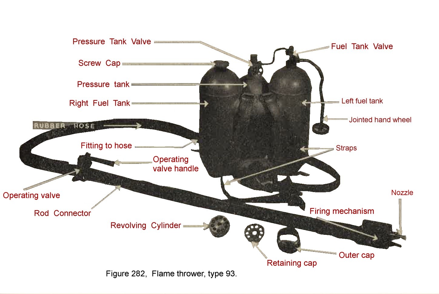
b. WWII Japanese Flame thrower Type 100.
Very similar to type 93 flame thrower. The fuel units of the two types are identical as are range and duration of flame. The differences are found in the flame guns as follows:
Japanese WWII flame thrower comparison table
| TYPE 93 | TYPE 100 | |
| Over-all length | 47 1/8 inches | 35 1/2 inches |
| Weight | 10 pounds | 8 1/2 pounds |
| Nozzel outlet tip | Fixed | Removable |
| Diameter of cartridge | 0.44 inch | 0.484 inch |
| Chambers of revolving cylinder | 10 | 10 |
c. Pyrotechnichs See Chapter 10.