Donate
| CHAPTER 2. | MECHANICAL TRAINING |
| |
|
| Section I. | Nomenclature, disassembly, and assembly |
| Section II. | Operation and functioning |
| Section III. | Stoppages |
| Section IV. | Ammunition |
| Section V. | Maintenance |
| Section VI. | Storage |
| Section VII. | Safety |
SECTION I. NOMENCLATURE, DISASSEMBLY, AND ASSEMBLY
4. General
The sight unit, recoilless barrel, XM63; recoilless barrel, XM64; mount, tripod, XM120; and mount, tripod, XM121 are disassembled only by qualified ordnance personnel. Disassembly of the spotting rifle, XM69, is limited to the extent necessary for ordinary care and cleaning (field stripping). Detailed disassembly of the spotting rifle is done by ·ordnance personnel only.
5. Light Weapon System, XM28
The light weapon system, XM28, consists of recoilless barrel, XM63; mount, tripod, XM120; mount, rifle, spotting; rifle, spotting, XM69; kit, vehicle adaption, 8387688; sight unit; and port-a-packs, XMl, XM2, and XM3.
6. Recoilless Barrel, XM63
The barrel is made of titanium and consists of three major parts: barrel, barrel chamber, and nozzle (breech). These parts are threaded and assembled by the manufacturer. The chamber is considerably expanded; however, it terminates in a constricted nozzle-like opening. About 12 inches from the muzzle end of the barrel, there is a flat sleeve which indicates the position to attach the barrel to the mount. The elevating screw is attached to the forward portion of the chamber and supports the chamber end of the barrel.
7. Mount, Tripod, XM 120
a. General.
The mount (fig. 3) is made of aluminum and consists of a front and two rear leg assemblies. Each leg can be telescoped to conform with the terrain. An integral part of the mount is the cross tube assembly, two supporting leg struts, and the gimbal ring assembly. The rear legs are held in place by the cross tube assembly which also supports the elevating mechanism. The two supporting struts, located on the cross tube assembly, engage the front leg dovetails on each side of the front leg. The rear legs are attached to the front leg at the top. This prevents spreading and holds the mount stable in either high or low firing position. The firing position of the mount (high or low) is determined by the range.
b. Traversing Knob.
The traversing knob is secured to the traversing screw located on the elevation bracket. The elevation bracket is attached to the barrel. With the traversing screw centered, the weapon may be traversed -10 mils right or left from center. Turning the knob clockwise traverses left; counterclockwise traverses right.
c. Elevating Screw.
The elevating screw is part of the elevation and traversing assembly and is located below the transversing knob. Turning the screw to the left raises the weapon; turning to the right lowers it.
d. Quick-Release Pins.
The quick-release pins are located in the outer Gimbel ring. Purpose of the pins is to hold the recoilless barrel Xl\MI3 in the mount; and act as a pivot, allowing the barrel to turn. To operate, grip the head of the pin and pull out about a half inch. At this point the spring-loaded plunger falls into its seat and holds the pin in the open position. To close the pin, push in about a half inch and the spring loaded plunger falls into the closed plunger seat, holding the pin in the closed position.
e. Cross Tube Leg Lock Handles.
Two leg lock handles are located on either end of the cross tube. Purpose of the handle is to attach the cross tube to the rear legs and provide quick disassembly and assembly of the tripod mount. To operate the leg lock handle, turn down and toward the center of the cross tube. Place rectangular hole in the elevator lock of the cross tube over the shoulder screws of the rear legs. As the shoulder screw head protrudes through the rectangular hole, turn the leg lock handle perpendicular to the top of the cross tube. Pressing the
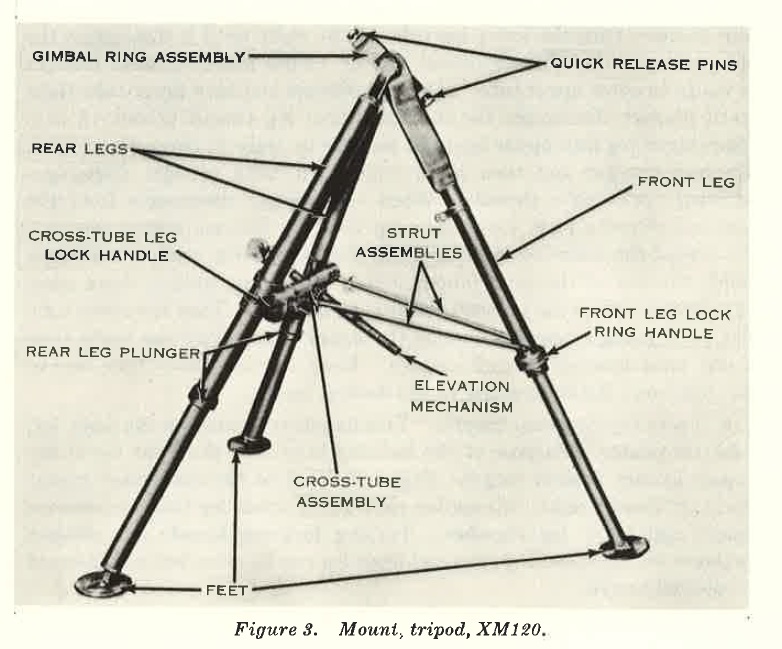
FIGURE 3.
leg lock handle up and away from the cross tube locks the handle in position and secures the cross tube to the rear leg. To remove the cross tube from the rear leg, push the handle straight down toward the center of the cross tube. This aligns the rectangular hole in the clevis lock and the head of the shoulder screw. The cross tube is now removed from the rear leg.
f. Cross Tube Elevation Lock Handle.
This handle locks the elevation tube in the cross tube assembly. The elevation lock handle may be traversed 160 mils left or right with an overall traverse of 320 mils. When the handle of the cross tube elevation lock is perpendicular to the cross tube, the elevation tube can be inserted into the hole in the center of the handle. In this position, the elevation tube and handle may be moved right or left. Turning the handle to the extreme left (near parallel to the cross tube) locks the elevation tube into position from which it cannot be traversed, elevated, or depressed. To release the elevation tube, turn the lock handle perpendicular to the top of the (TOSS tube).
Note: When the elevation lock handle is in the perpendicular position, the barrel of XM63 must be supported to keep it off the cross tube. Asbestos mittens are required when the weapon is hot.
g. Lower Tube Rear Leg Plunger.
The rear leg plunger is spring-loaded and located about 1-1 inches from the foot of each rear leg. Purpose of the plunger is to hold the lower tube inside the upper tube of the leg when it has been screwed into the upper leg more than 18 inches. To operate the plunger, turn the lower leg tube to the right until it disengages the internal upper leg threads (about 18 in.). Push lower leg until plunger is ready to enter upper tube. Depress plunger and turn lower tube right until plunger disengages the internal upper leg thread (about 18 in.). Push lower leg into upper leg until plunger is ready to enter upper tube. Depress plunger and turn lower tube right until plunger disengages internal upper tube threads. When the plunger disengages from the internal threads, push lower tube up into the internal spring retainer. To extend the lower leg, pull leg down until the spring retainer no longer holds the top of the tube (about 5 in.). Continue pulling down until the plunger enters the internal upper tube threads. Turn the lower tube left until plunger appears outside the upper tube. Pull the lower tube down until internal threads engage. Keep turning lower tube to the left until rear leg is extended to the desired length.
h. Front Leg Lock ring Handle.
This handle is located on the front leg. near the center. Purpose of the lock ring is to hold the front leg of the tripod at any desired length. Stand in front of the assembled mount and turn handle right; this applies pressure to upper leg tube and secures upper and lower leg together. Turning lock ring handle left releases pressure on the upper leg tube and front leg can be extended or depressed to desired length.
i. Right and Left Strut Assembly.
The strut assembly is a tube, about 26 inches long, with a dovetail slot in one end and a hole for a clevis pin in the other end. The clevis pin end is attached to the cross tube, and the dovetail end attaches to the front leg. The strut assembly holds the front leg of the mount in firing position. The dovetail provides disassembly and assembly of the mount. To assemble the right and left strut assembly to the protruding dovetail on either side of the front leg, place the dovetail of the strut below the front leg dovetail and pull the strut assembly up. A spring-loaded plunger in the dovetail end of the strut assembly snaps into the plunger seat in the front leg dovetail and secures the strut assembly. Disassemble the strut assembly from the front leg by holding the leg and pulling up on the assembly. The plunger will pull back from its seat and the strut will slide up off the front leg dovetail.
j . Strut Springs.
Two (spring-wire) strut springs are located on the right strut assembly. The strut spring holds the right and left strut in folded position against the cross tube. (Do not detach the struts from the cross tube.) To unfold struts, press down on the hook end of the spring while supporting the struts. To attach the spring, fold the struts, place the left strut in the hook opening, and press the loop of the hook against the left strut. When springs are not being used to hold the struts in the traveling position, they remain on the c'foss tube assembly.
8. Mount, Rifle, Spotting, 20-MM, XM69
a. General.
Mount, rifle, spotting (fig. 4), attaches spotting rifle XM69 to barrel XM63. It is designed to be compatible with the arrangement of the barrel and tripod mount, and is placed on the underside of barrel XM63 to minimize the effects of recoil. In this position, the XMIOI spotting projectile clears the major caliber (279-mm) projectile by one inch. The mount houses a positive displacement device capable of movement in I-mil increments for both azimuth and elevation for the spotting rifle. The mount system includes a bracket made of weldable titanium shrunk-fitted to barrel XM63. The rear of the bracket houses retaining hardware, and the front houses the adjustment device. The cross-leveling device for the sight unit is located on top of the bracket above the barrel, XM63.
b. Insertion and Removal of the Spotting Rifle from the Mount.
This operation is accomplished from the rear of the bracket. Remove the quick-release pin (fig. 5) to allow ball sections on the rifle to clear spline seat. The quick-release pin is attached to left side of the 20-mm spotting rifle bracket by lanyard. This pin retains the spotting rifle in the bracket if it is released from its interrupted thread. Depressing the locking plunger (using quick-release pin) (fig. 6) in the ball section of the spotting rifle allows the rifle to be rotated 60° counterclockwise. When splined ball sections on the rifle are alined with slots in the ball seat retainer, the rifle may be removed (fig. 7). Field stripping of XM69 can be accomplished while XM63 barrel is on the tripod mount. The XM69 spotting rifle can ahm be removed from its mount while the XMi: barrel 1s on the tripod mount.
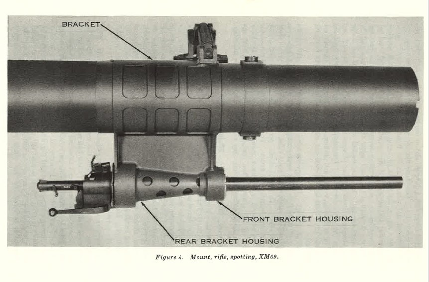
FIGURE 4
c. Procedure fnr Adjusting the X M69 Spotting Rifle.
(I) A positive displacement type device is used to adjust alinement of the XM(i9 spotting rifle. This adjustment is required to compensate for misalignment of major caliber barrel and spotting rifle barrel. This device provides azimuth and elevation adjustment of the spotting rifle and positive lock after adjustment. It is tamper proof and permits a total of 5-mil adjustment either right or left and elevation or depression in increments of 1 mil.
(2) Azimuth and elevation rings are engraved to denote mil adjustment of right, left, elevation, and depression. These rings are mounted in the front adjustment housing (fig. 8) and, after the desired adjustment is set, are locked in position by means of the seal and retainer. To readjust the setting of the spotting rifle, the cotter pin is removed and the retainer is unscrewed (fig. 9) and moved forward along the spotting rifle barrel. By insertion of a tool through holes in the housing, the entire adjustment unit and seal is slid forward until clear of the housing (fig. 10). After removing the package, either ring is then turned to the desired mil setting and the unit is replaced on the barrel and returned into the housing, locked by the
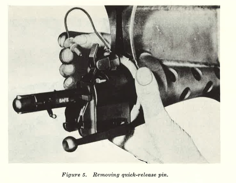
FIGURE 5
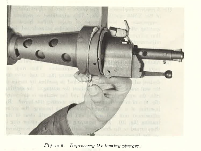
FIGURE 6
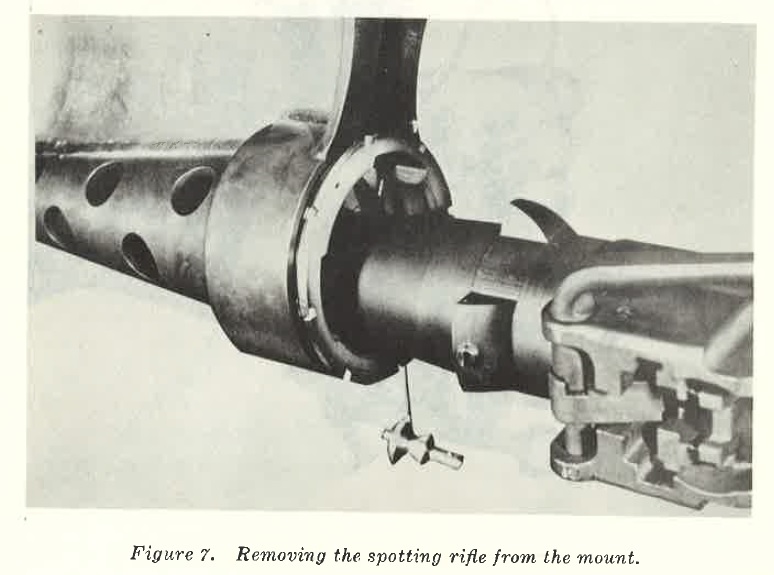
FIGURE 7
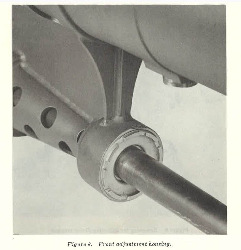
FIGURE 8
9. Rifle, Spotting, XM69
a. General.
The spotting rifle, XNIG9, is a single shot, manually operated, dropping breech block weapon. It is designed as a range determining device for the XM28 light weapon system.
b. Disassembly.
Spotting rifle is disassembled (field stripped) in the following manner:
(I) Open breech to insure weapon is clear, close breech, turn safety to FIRE position, and depress trigger lock and trigger. Pull safety outward one-eighth of an inch and turn clockwise to the disassemble notch.
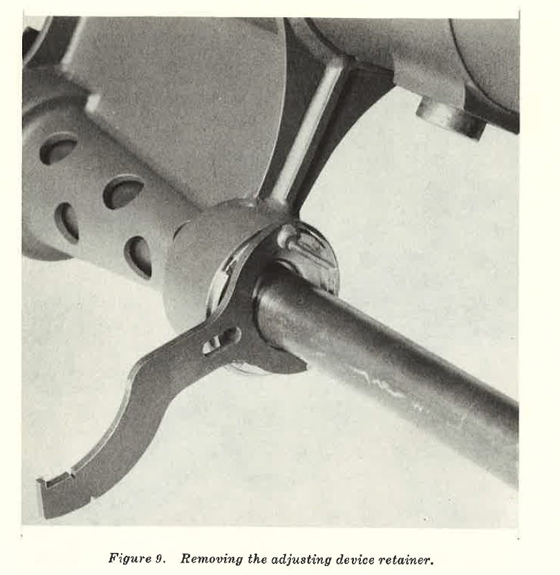
FIGURE 9
(2) Grasp trigger housing assembly and disengage safety lever from the breech block assembly by rotating and pulling outward. Care must be taken while disengaging safety lever from breech block assembly, as trigger housing assembly will move rearward if not manually restrained. Compression of the striker spring causes movement. Failure to grasp the trigger housing assembly firmly and regulate movement, will allow the striker spring to propel the trigger housing assembly to the rear with sufficient force to cause injury to personnel or damage to the part. The trigger housing assembly is a permanent type assembly and is not further disassembled (fig. 11).
(3) Remove striker spring (fig. 12).
(4) Slide striker housing and striker rearward. At the end of rearward travel, remove the striker from the breech block by removing the striker guide pin (figs. 13 and 14).
(5) Remove the breech block assembly by supporting it from the bottom and rotating the operating handle downward (counterclockwise). At the same time, push downward on the breech block assembly until it is free and drops through the breech block housing (fig. 15).
(6) While supporting the actuator from the bottom with one hand to prevent damage if dropped, continue counterclockwise rotation of the operating handle with free hand, pulling outward at the same time. When the opera.ting handle has been rotated 180°, it can be withdrawn from the pivot hole in the breech block housing (fig. 16).
(7) Removal of the operating handle completes field stripping of the weapon (fig. 17). Further disassembly is authorized only for ordnance personnel.
c. Assembly. Assembly of the spotting rifle is accomplished as follows:
(1) Replace opera.ting handle in recesses.
(2) Replace actuator, engaging actuator slot on breech block and operating handle.
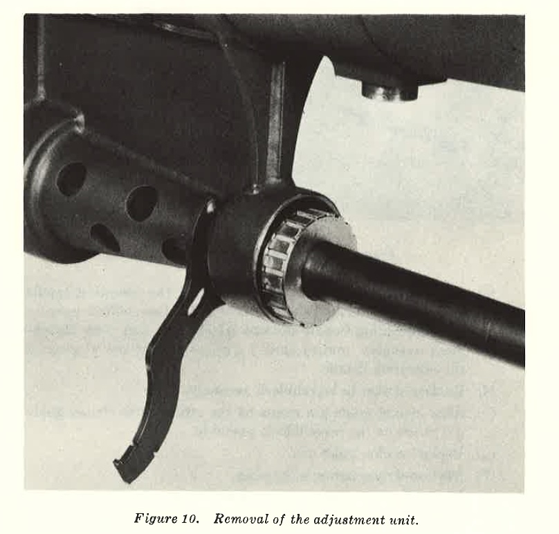
FIGURE 10
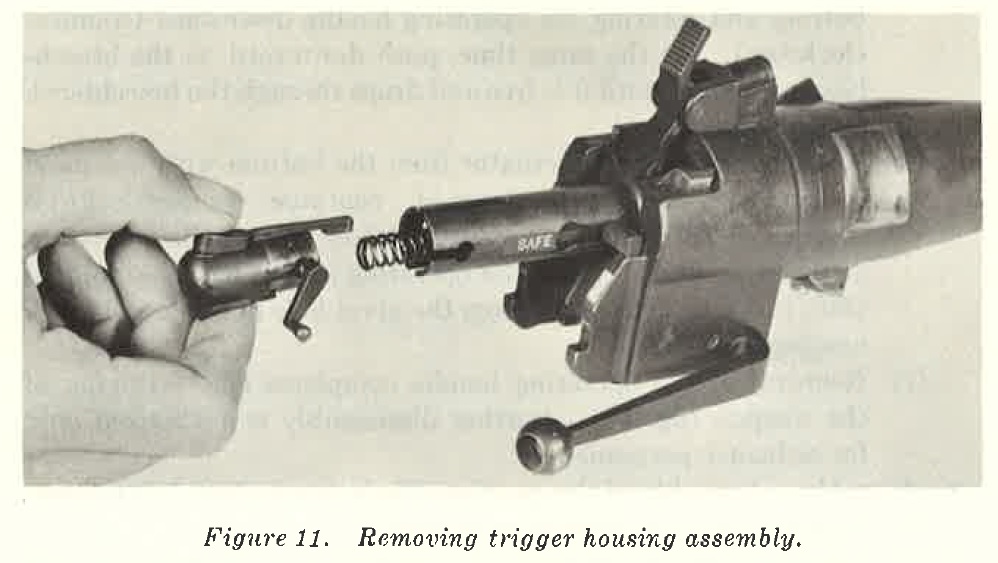
FIGURE 11
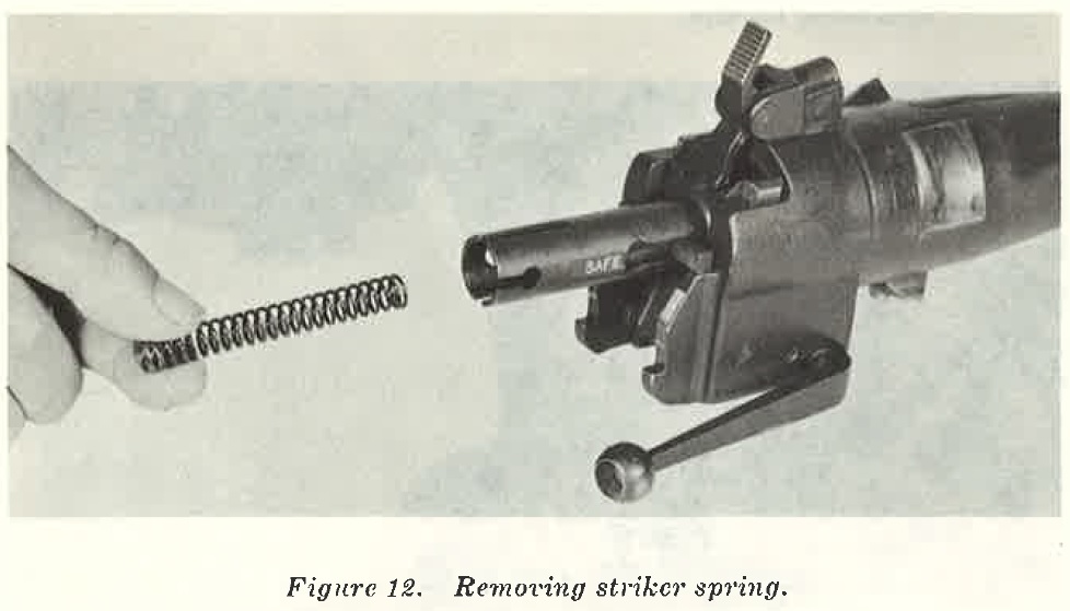
FIGURE 12
(3) Replace breech block assembly by placing the operating handle in down rod position, insert breech block in breech block recesses, move operating handle upward (clockwise), and push breech block assembly upward until it engaged breech block recesses of the operating handle.
(4) Replace striker in breech block assembly.
(5) Aline striker guide pin recess on the striker with striker guide pin recess on the breech block assembly.
(6) Replace striker guide pin.
(7) Replace striker spring in housing.
(8) Place trigger asHembly over striker spring and push to engaged position.
FIGURE 12
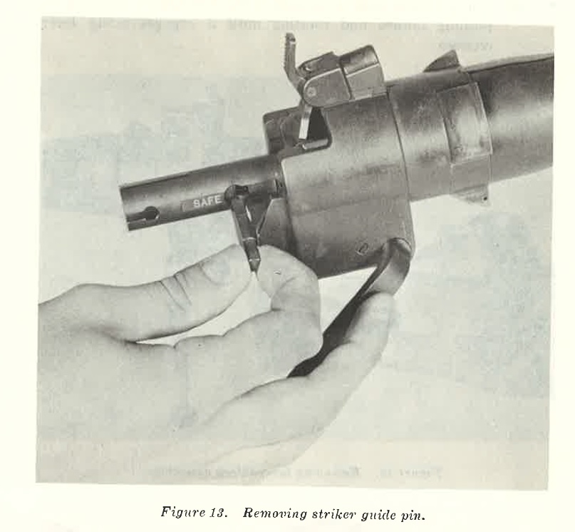
FIGURE 13
(9) Engage safety lever in recesses of the breech block assembly by pushing inward and rotating until it engages safety lever recesses.
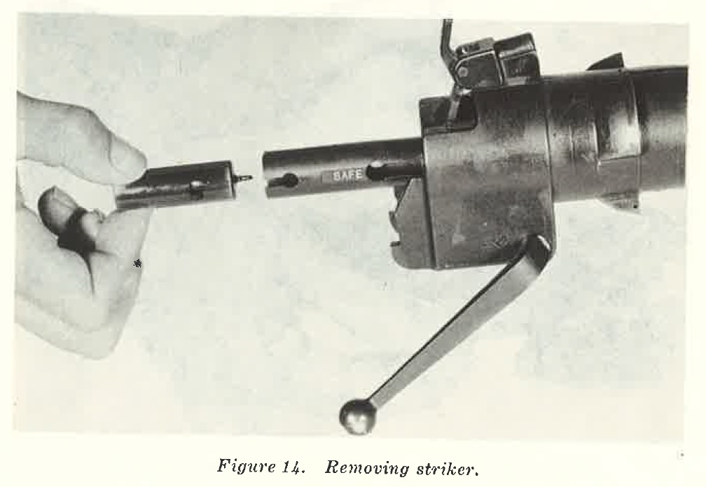
FIGURE 14
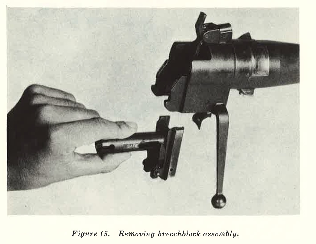
FIGURE 15
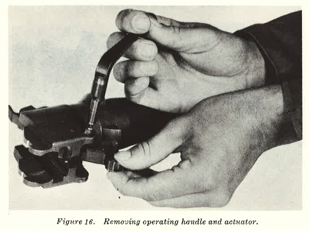
FIGURE 16
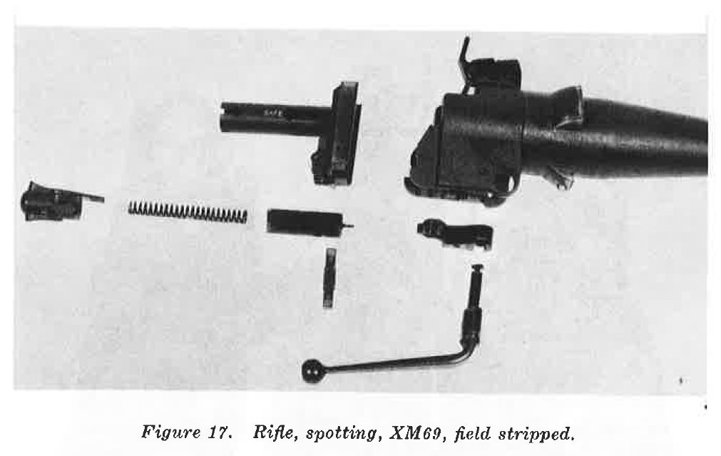
FIGURE 17
10. Port-a-Packs, XM 1, XM2, _XM3, (fig. 18)
a. General.
Port-a-packs are made to transport the light system in dismounted operations on bnck8 of squad members. The squad (5-man) is capable of carrying the weapon and ammunition (one nuclear projectile) about three miles before becoming excessively fatigued. There are three types of port-a-packs (pack boards): A, B, and C. Each type carries a specified portion of the weapons system.
Pack A, XM1, (assistant gunner)
carries projectile, atomic, super caliber, 270-mm, XM388;
pack B, XM2, (gunner)
carries recoilles8 barrel, XMn:~, spotting rifle, XMG9 and sight unit;
and pack C, XM3 (loader)
carries propellant charge XM75, launching piston XMI, and mount XM120.
The squad leader carries radio AN/PRC-10; and the computer carries radio AN/ PRC-10, plotting board, and firing tables. Port-a-packs are lightweight, tubular, frame pack boards with shoulder straps and padding. Equipment is fastened to the port-a-packs by straps and fasteners which are quickly fastened or unfastened. A zipper-closed, water repellent cover is provided for nuclear projectile port-a-pack A.
b. Pack board, XMJ. To load pack board XMI, open canvas cover by unzipping. With toggle strap assembly open, lay projectile on pack board frame with fins in tail support. Place toggle strap assembly around the largest diameter of the projectile. Place T-bolt in the slot in the toggle strap assembly and press the body of the toggle strap assembly down. Place thermometer, MIAl, in mounting brackets. Close zipper on canvas cover to protect projectile. To remove projectile, reverse above procedure.
c. Pack board, XM2. To load pack board XM2, traverse the traversing mechanism as far to the left as it will go. Place the nozzle of the light weapon in the sewn loop of the strap attached to the pack board. The
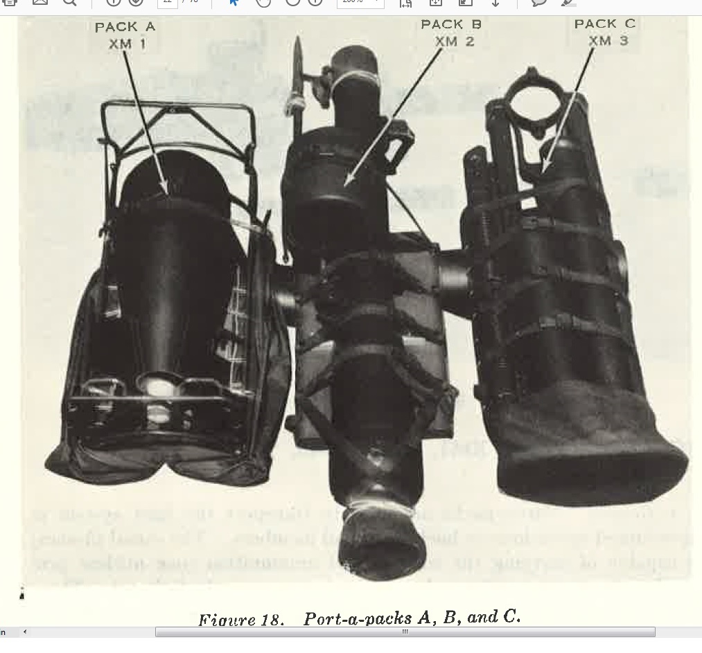
FIGURE 18
elevation medtani:,;m l'csb, on wooden cross block. Place muzzle end of lighL weapon and spotting rifle in contours of metal litmp ut top of the pack board. Adjust-it. loop t:>trap by pulli11g strap ends until the muzzle end of the light weapon protrudes slightly less than one meter above the top of the pack board. Swing elevation and traversing mechanism forward against the barrel. Pince sight unit (in ·use) between barrel of spotting l'if! · und i,ight mount. Using hold down straps, secure weapon to pack board by placing loop ends over inverted hook on sides of pack board, and adjust straps to securely hold the load on the pack board.
d. Paclrbnarri, X MS. To load pack board XM3, fold tripod mount and place on pack board, inserting leg. in to the support pouch with fitting a tachme11t studs up. Pluce cross tube assembly alongside mount. The laun •hfog piston, in container, is placed 011 top of mount with one end in the support pouch. The propellant, ·barge is placed alongside the pi. ton container with one end in the support, pouch. Secure straps of support, pouch through rectangular holes to buck of pack board. Seow·e load ·o pack board I iLh four hold down straps. To remove load, reverse procedure.
11. Kits, Vehicle Adoption
a. Vehicle adaption kits adapt the light and heavy weapons to carriers. There is a different type adaption kit for each vehicle on which the weapon is mounted. Adapter kit 8:~87688 adapts the XM28 light weapon to a ¼-ton truck, l\tI:38A 1 D (fig. 19). The X1vI29 (heavy weapon) is mounted on a ¼-ton truck, 1Vrn8A1D (fig. 20) by means of adapter kit 8387689 or stowed in a full-tracked armored personnel carrier, Ml];~ (fig. 21). Components of these kits include a weapon mount, ammunition storage boxes, storage brackets, a barrel traveling lock, and attaching hardware. The adaption kit for the light weapon provides a complete weapon mount, while the kit for the heavy weapon utilizes carriage from the tripod mount.
b. The adaption kit for the M113 provides racks, brackets, and straps for securing the weapon in the vehicle as well as seats for the crew.
(1) Data:
|
(2) The barrel and carriage are stowed on the right side of the compartment floor. A support skid and saddle support the barrel and carriage. The carriage is attached to the barrel for stowage. An anti-rotation device is used to prevent movement of the weapon while stowed.
(3) The projectiles are stowed on the left side of the compartment floor. Individual stowage is provided for the projectiles, positioned with stabilizing fins up. Pressure applied at the fin end by adjustable clamps forces the projectile nose into a rubber cushioned socket that tdines the projectile and prevents movement.
(4) The propellant charges are stowed both horizontally and vertically on the right sponson and floor.
(5) The liwnching pistons are stowed above the propellant charges on racks suspended from the top and right wall.
(6) A combination bracket suspended from the top and left wall provides for stowage of the tripod, aiming circle, plotting board, cleaning staffs, and sight unit.
(7) The aiming circle is stowed on the left side of the compartment floor, forward of the projectiles. It is secured with strap clamps.
(8) The l\'114 chest (aiming post lights) is stowed under the crew seat (forward left side) and is secured to the floor with straps.
(9) The aiming posts are stowed on the floor under the projectile mounts.
(10) The binoculars, compass, gunners' quadrant, and thermometer are stored forward of the fuel tank on the left sponson.
12. Mount, Vehicle, Light Weapons, XM28
a. General.
Vehicle mounts consist of a frame assembly and a cradle assembly. The frame assembly is used to attach the XM28 weapon to the ¼-ton truck, M38A1D. The cradle assembly attaches to the barrel and is supported by the frame assembly attached to the vehicle.
b. Traverse Lock Assembly Knob.
This knob is located on the traverse lock assembly mounted on the lower rear portion of the vehicle mount. The knob locks the mount in position after traversing, and releases for traversing. The knob is rotated clockwise for locking and counterclockwise for unlocking.
c. Traverse Lock Assembly Lever.
The lever is a slotted lever, pivoted near the center, with a spring pin protruding from the sides. It is found on top of the traversing lock assembly mounted on the lower rear portion of the vehicle mount. The lever engages or disengages a gear sector from the traversing spur gear. For free traverse, lift up on lever until protruding spring pin clears the lug on the traversing lock bracket. Pull the bottom of lock assembly from spur gear until protruding spring pin catches on front of bracket lug. Reverse procedure to engage lock assembly with spur gear.
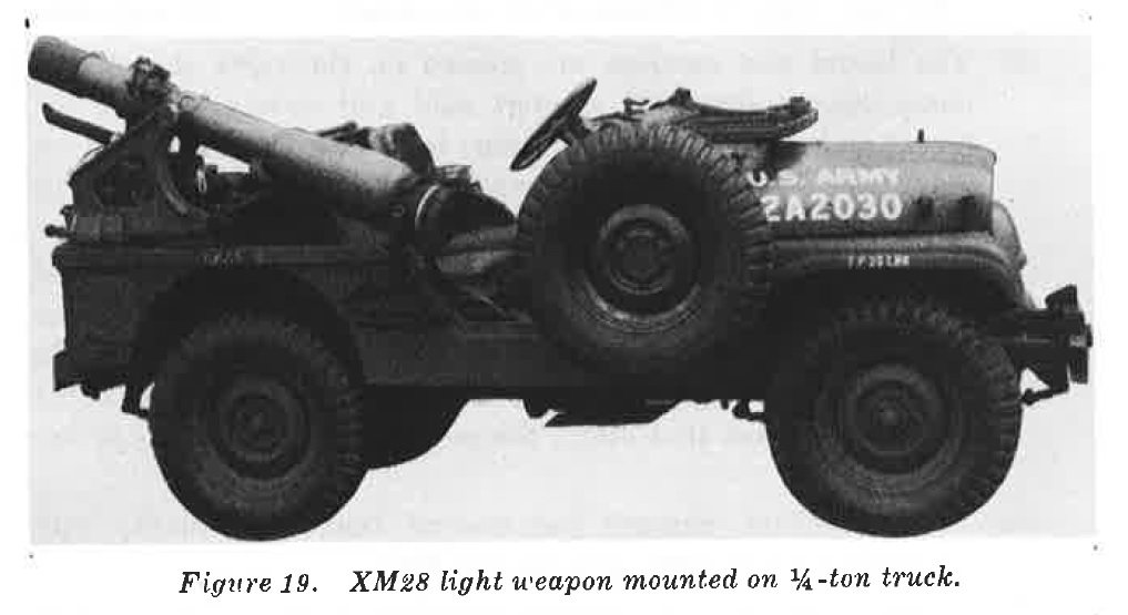
FIGURE 19
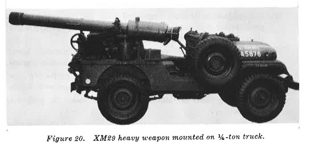
FIGURE 20
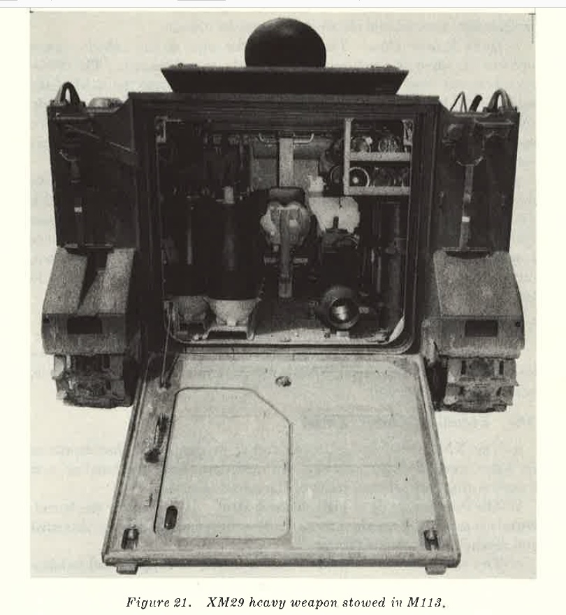
FIGURE 21
d. Traversing Lock Gear Sector.
The sector is a pivoted lever with milled gear teeth. It is part of the traversing lock assembly mounted on lower rear of vehicle mount. The gear sector is used to traverse the mount when laying on target. To lay on target, place mount in free traverse and lay on or near target. Engage traverse lock with traversing spur gear. For final adjustment (minor changes), push lock gear sector to left to traverse left or to right to traverse right. When weapon is laid correctly, lock traversing lock assembly.
e. Elevating Af mechanism Tube Lock Handle.
The tube lock handle is an X-type handle, located in the yoke assembly attached to the lower front end of the vehicle mount. The handle is used to lock the elevation mechanism on the ,rnapon in the yoke us8embly. To lock elevation mechanism, turn handle clockwise; reverse to unlock.
f. Quick-Release Pins. The quick-release pins of the vehicle mount operate the same as quick-release pins of the tripod mount. The difference between these pins is a wire spring which slips over the head of the pin to provide a positive lock to hold pins in the closed position. Quick release pins are located in top and bottom of the cradle assembly. The spring must be pressed off the head of the quick-release pins before they can be pulled open.
g. Traveling Lock. Purpose of the traveling lock is to 8Upport the weapon and to hold it in position while traversing rough terrain; this prevents damage to mount. To open the traveling lock, pull and raise handle until the clevis disengages from the hook, pull clevis down into handle and pull clamp up. To close the traveling lock, pull clamp down, raise handle and pluce clevis in clamp hook, push handle down and in toward body of traveling lock.
13. Heavy Weapon System, XM29
The heavy weapon system, XM29, consists of the following major components: recoilless barrel, XM64; mount, tripod, XM121; kit, vehicle, adaption, and sight unit.
14. Recoilless Barrel, XM64
a. The XM64 recoilless barrel is similar in shape and characteristics to light weapon barrel XM63. In addition, carrying handles and trunnion rings are integral parts of the barrel assembly.
b. The bullet is made of high strength steel. It consists of the barrel, barrel chamber, and nozzle (breech). The three components are threaded and assembled by manufacturer.
c. Two trunnions are located at rear of barrel to support and balance the height of the weapon on its carriage. A support ring encompasses the barrel and is connected to the elevation screw of the carriage.
15. Tripod Mount, XM 121
a. General.
The tripod mount, XM121 (fig. 22), consists of u tripod assembly (lower portion) and a carriage assembly (upper portion).
b. Tripod Assembly.
The assembly is made of aluminum. It consists of a post (pintle) and three folding legs. The legs operate independently of each other, and when fully extended, snap into u spring latch at the hinge. The latch assembly is composed of two springs and u welded latch, and is located between the leg brace and the leg brace link. The latch assembly holds the leg brace rigid or permits its collapse. To fold tripod legs, push up on latch while folding legs in against the post cone.
c. Carriage Assembly.
(1) General.
The carriage contains elevating and traversing mechanisms and is easily detached from the barrel and tripod for greater man-transportability. The carriage which is made of steel and weighs 60 pounds, is readily adapted to the vehicular mounting by a post (pintle).
(2) Lock pins.
On the carriage are located two trunnion bearings and two lock pins which retain the barrel trunnions in position on the carriage. The lock pins have a plunger in the center that controls two small plungers in the end of the pin. These are attached to the top of the carriage assembly with lanyards near the trunnion bearings. To operate lock pin, depress plunger in body of lock pin. This will retract the small plungers in opposite end of pin, and the lock pin may be inserted or removed from the hole in the trunnion block. The plunger is spring-loaded and will return to the locked position.
(3) Elevating screw barrel lock assembly.
The barrel lock is spring loaded and pinned to the top of the elevating screw to secure the barrel to the elevating mechanism while providing a quick method of disconnecting the barrel from the mount. To open lock assembly, press down on lock. Release pressure on lock and lock will close by spring pressure.
(4) Elevation hand wheel. Its purpose is to make major changes in elevation. Turning hand wheel clockwise elevates the weapon. Turning counterclockwise depresses weapon.
(5) Elevation hand knob. This knob is located in center of elevation hand wheel. When knob is operated, it rotates in the same direction as the hand wheel. The purpose of the elevation hand knob is to make minor adjustments in elevation for a final lay on the target.
(6) Traversing hand wheel handle. The handle is located on the rim of the traversing hand wheel, and is used to make minor adjustments in deflection for a final lay on the target. Turning traversing mechanism clockwise traverses weapon left; counterclockwise traverses weapon right.
(7) Traversing clutch release handle. The clutch release handle is located on the left side of the carriage. It controls the clutch spring which engages or disengages the action of the traversing hand wheel. There are two positions for the clutch release handle, up and down. A plate is attached to the carriage opposite the clutch release handle indicating DOWN position. It reads FREE TRAVERSE to indicate carriage assembly may be traversed 6,400 mils. To operate the clutch release handle, pull out and turn it up or down in an arc. When the handle assembly reaches the top of the arc, a spring-loaded pin inside the handle will extend into a hole in the carriage. This will secure the handle in a position where action of the traversing mechanism is engaged. To place traversing release handle in DOWN (free traverse) position, reverse procedure for UP position.
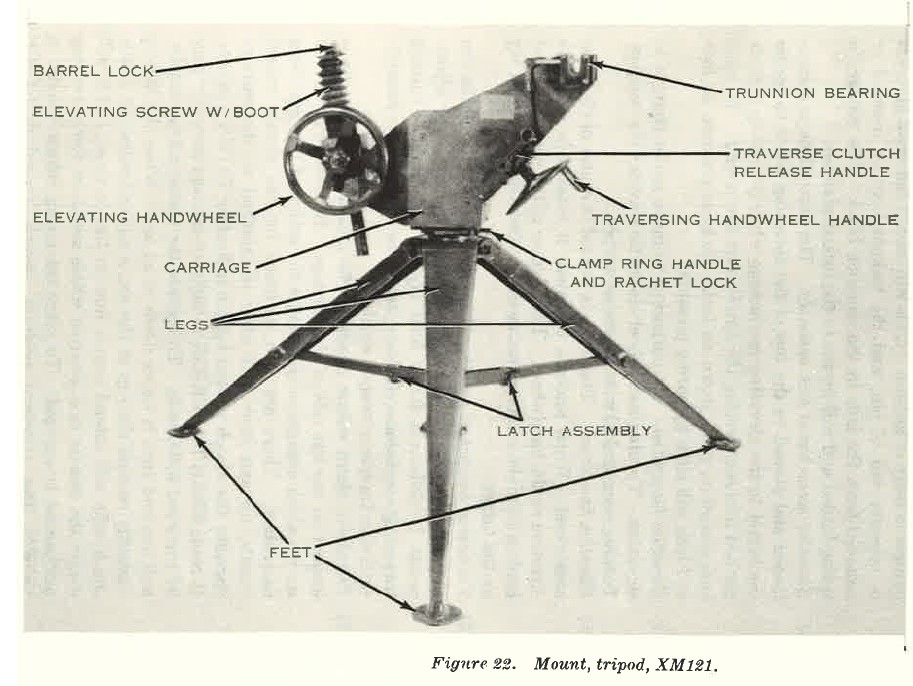
FIGURE 22. Mount, tripod, XM121
(8) Clamp ring handle and ratchet lock.
(a) The clamp ring handle is a headless stud screwed into the clamp ring. There are two such handles located 180° apart on the clamp ring. The clamp ring is found on the bottom of the carriage assembly, and its function is to lock the carriage assembly to the tube post dowel pin of the tripod or the adapter post when the carriage assembly is mounted on a ¾-ton carrier, M38A1D.
(b) To lock the carriage assembly to the mount, the operator must place the lock handle on the clamp ring handle and then turn the clamp ring counterclockwise about one inch. The release ratchet lock and clamp ring is locked on a post of the mount. To unlock the clamp ring, depress ratchet lock against clamp ring, turn it clockwise about one inch, and release ratchet lock.
(c) When not in use, place lock handle with its attached chain in the spring clip located on the right side of the carriage assembly. Traversing the carriage will break the lock handle chain if it is not removed from the clamp ring handle after it has been used to operate the clamp ring.
SECTION II. OPERATION AND FUNCTIONING
16. Spotting Rifle, XM69
a. Operation.
(1) Safety.
The safety is on the right side of the breech block assembly near the trigger and trigger lock (fig. 23) . Its purpose is to lock the trigger and trigger lock to prevent firing of the 20-mm spotting rifle, and also acts as a retainer to hold the trigger assembly in the breech block assembly. The spotting rifle is locked (safe) when the pointed portion of the safety is at the 9 o'clock position to SAFE stamped on the right side of the breech block assembly. Turning the safety to 11 o'clock position places it in firing position. Turning safety to 1 o'clock positions it for removal.
(2) Trigger.
The trigger, safety, and trigger lock are components of the trigger assembly. Primary purpose of the trigger is to fire the weapon. The spotting rifle cannot be fired, however, without the safety being in firing position and operating the trigger lock before depressing the trigger to fire.
(3) Trigger lock.
The trigger lock is directly below the trigger. A coil spring inside the trigger assembly forces the trigger and trigger lock apart. Purpose of the trigger lock is to keep the trigger from being depressed. To operate trigger lock, turn safety to firing position, then press and hold trigger lock inside trigger housing.
(4) Loading.
Rotate operating handle down, and safety counterclockwise to SAFE position. Manually insert 20-mm spotting cartridge into chamber until extractor engages cartridge rim. Rotate operating handle up to closed breech position.
(5) Firing.
Rotate safety clockwise to FIRE position and depress trigger lock and trigger.
(6) Unloading.
Rotate operating handle down and safety counterclockwise to SAFE position. Press extractor abruptly with side of hand or thumb. This causes cartridge case to be ejected to rear over breech block assembly.
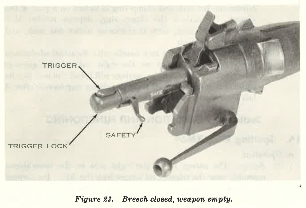
FIGURE 23
b. Functioning.
(1) Breech housing. The housing is on the threaded breech end of the barrel and supports the entire breech mechanism. The housing has breech block ways at an angle of three degrees from perpendicular to the bore. In dropping, the breech block performs the initial extraction of the case. The striker guide pin protrudes on either side of the breech block and rides down the angular cam surfaces on the rear of the breech housing. The striker guide pin limits the vertical travel of the breech block by engaging the notches below the cam surfaces. The location of shelves on top of the cam surfaces assures the breech block is fully locked before the striker guide pin will clear the shelves allowing the striker to fall and ignite the round.
The angular cam surfaces also engage the striker guide pin and cause it to move to the rear, thereby cocking the weapon. The breech block is raised or lowered by manually lifting or lowering the operating handle (mounted in a traverse hole in the lower part of the breech housing) which rotates the breech block actuator. Ball detents, seated in the actuator sockets, hold the breech block closed when the operating handle is in the horizontal position. The extractor on top of the breech housing performs retention and extraction functions only when the breech block is in the open position (operating handle down).
(2) Breech block assembly. The face of the breech block has T-slot extractor lips which engage the cartridge rim. The block also has side rails which slide in ways in the breech housing. Because the ways in the breech housing are three degrees from perpendicular to the bore, lowering the breech block loosens the case in the chamber and accomplishes the first 0.040 inch of case extraction. The striker is spring-loaded and has a cylindrical cavity at the trigger end into which the striker spring is assembled. The striker shaft passes through the front transverse hole and aligns and retains the striker. The rear shoulder of the top notch in the striker is a sear engaging surface.
The striker shaft prevents rotation of the striker which would disengage it from the sear and cause accidental ignition of the round. Initial extraction of the striker is effected by the interaction of the retractor with the striker shaft. The retractor is cammed rearward by the actuator during initial operating handle motion in order to withdraw the striker from the primer indent before the breech block drops. Cocking occurs when striker guide pin contacts cam surface on rear of breech housing. Firing mechanism is basically composed of a spring-loaded trigger, trigger loc;k, trigger housing, and safety. The trigger lock must be depressed just prior to depression of the trigger in order to permit firing of the rifle.
(3) Spotting rifle, XM69. Functioning of the spotting rifle may be divided into eight phases: feeding, chambering, locking, firing, unlocking, extracting, ejecting, and cocking.
(a) Feeding.
Downward pressure applied manually on operating handle will cause breech block assembly to move downward, opening the chamber of weapon (fig. 24). Cartridge is manually placed in chamber and pushed forward.
(b) Chambering.
Cartridge rim engages extractor claw automatically and cams it upward into a toggled position. As a result, the extractor acts as a round retainer while breech is being locked.
(c) Locking.
Locking occurs when operating handle is lifted, causing actuator to raise breech block (fig. 25). The weapon cannot be fired before action is locked since the striker shaft is not aligned with the related shelf in breech housing.
(d) Firing.
Clockwise rotation of safety (to FIRE position) will free trigger lock. Squeezing trigger lock removes the block which prevents trigger motion. Squeezing trigger now causes the sear surface of the trigger to disengage from the shoulder on the striker, and this allows the spring to drive the striker forward until it strikes the primer of the loaded cartridge and fires the round.
(e) Unlocking.
Initial movement of the operating handle, as it is manually pushed downward, causes the retractor to withdraw striker from primer before the breech block begins its descending motion, and prevents breakage of the striker tip. Withdrawal is accomplished because the initial free travel of the actuator permits actuator cam surface to contact and rotate retractor rearward before the actuator engages actuator pins located in breech block.
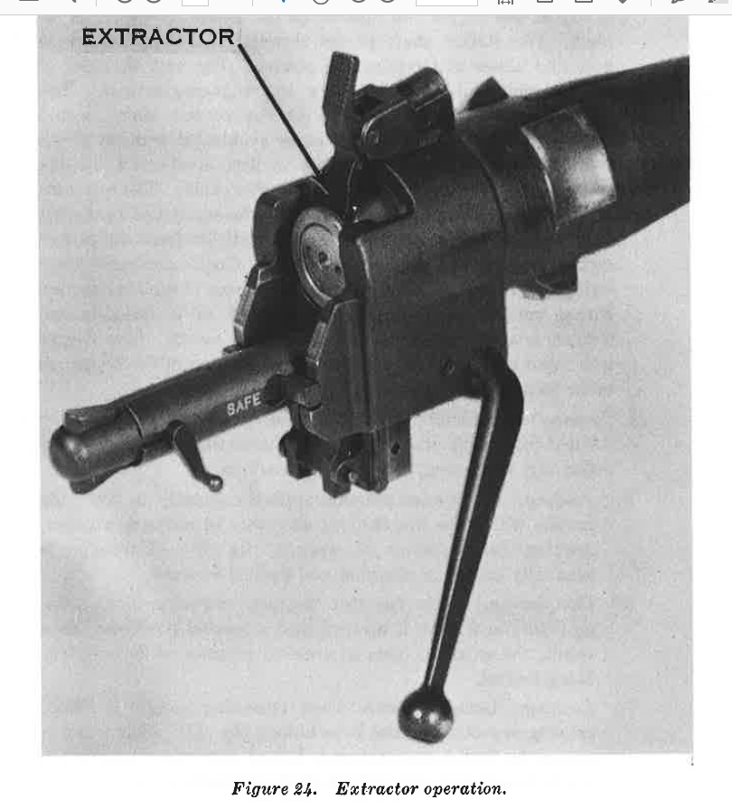
FIGURE 24
(f) Extracting.
Initial extraction takes place as the breech block drops, because the breech housing ways are three degrees from perpendicular to the bore. Lowering breech block loosens the case in the chamber and accomplishes the first 0.040 inch of case extraction. Rotation of operating handle stops when striker shaft reaches the lower shelf on bottom of breech housing cams. At this point, the breech block assembly is retained in OPEN position.
(g) Cocking.
Downward rotation of operating handle lowers breech block assembly, causing striker shaft to interact with cocking cams on breech housing and cock the striker.
(h) Ejecting. Pressing sharply on top of extractor with side of hand or thumb (fig. 26) ejects the fired case out of the chamber and clear of weapon.
17. Light and Heavy Weapon Systems, XM28 and XM29
a. General.
Operation and function of the light and heavy weapon are essentially the same; therefore, the operation and functioning of both weapons are discussed together.
b. Operation.
(1) Remove correct propellant charge (fig. 36) from its container, check to insure there are no cracks in the container, and load
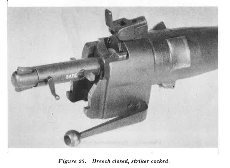
FIGURE 25
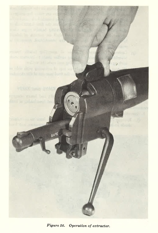
FIGURE 26
into barrel through the muzzle with base (collar section) toward nozzle of weapon. Push propellant toward nozzle until step of collar butts against rear wall of the chamber. This causes the collar section containing the firing mechanism to protrude through nozzle opening at rear of chamber.
(2) The correct launching piston (fig. 33) is removed from container. Remove protective (plastic) cap that covers obturator rings. Inspect rubber gasket for any defects. Locate separations in the two obturator rings 180° apart. Load (cap end first) through muzzle of weapon. When positioned properly, the indexing tab is engaged in key way located in muzzle of weapon.
FIGURE 27. Time setting dial.
(3) Remove nuclear projectile from container and set timer dial (fig. 27) to desired increment. Inspect dimple motors to insure they are recessed.
(4) Mate projectile (fig. 28) to piston adapter by aligning the bayonet pins (shear pins) in the projectile well with bayonet slots on the adapter. Turn projectile right and down for positive locking. Using screwdriver attachment on the spanner wrench, set height of burst (HOB) switch (fig. 28) to option desired, LO or HI. Again using screwdriver, turn ARM-SAFE switch (fig. 28) from SAFE to ARM position.
(5) Remove protective tape covering the opening in collar section. Remove spool of low energy detonating cord (LEDC) and proceed at 90° angle (right or left) away from the weapon, uncoiling cord until fully extended (22 meters). Holding spool, remove pin marked SAFETY. Grasp ring tagged PULL-TO-FIRE and as directions say, pull to fire.
c. Functioning.
When propellant is ignited, burning gases expand within the chamber causing an extremely high pressure. The expanding gases exert equal pressure in all directions within the chamber. Most of the pressure which causes a conventional weapon to recoil, escapes to the rear through the open nozzle, giving the weapon only a slight recoil. The pressure against the piston base forces piston (to which the major caliber projectile is attached) from the barrel. At the same time, some gases pass into the piston through a ¾-inch hole in the cap end. These gases cause a pressure (800 psi) within the hollow launching piston and exert pressure on the base of the projectile. This causes the projectile to separate from the launching piston by shearing the two bayonet pins in the well of the projectile base, and occurs three to five meters from muzzle of heavy weapon and one to two meters from muzzle of light weapon.

FIGURE 28. Projectile, atomic, super caliber, 279-mm, dummy, XM121.
SECTION Ill. STOPPAGES
18. Stoppages
a. A stoppage is any unintentional interruption in the cycle of operation which causes the weapon to fail to fire.
b. Most stoppages occur because of dirty, worn, or broken parts, and lack of lubrication. Crew members must be taught to watch for these defects and correct them before they cause a stoppage.
c. The stoppages will, in most cases, reflect the level of maintenance performed by the crew and its organization.
19. Misfire
A misfire is a complete failure to fire. This may be due to a faulty mechanism or a faulty element in the propelling charge explosive train. A misfire in itself is not dangerous, but since it cannot be immediately distinguished from a delay in the functioning of the firing mechanism (a hang fire) it should be considered a possible delayed firing until such possibility has been established. In the spotting rifle, such delay in functioning of the firing mechanism could result from the pressure of foreign matter such as grit, sand, frost, ice, or improper or excessive oil or grease. This may create a partial mechanical restraint which, after some delay, is overcome by continued force applied by the striker spring which is driven into the primer in the normal manner.
20. Hang fire
A hang fire is a delay in functioning of a propelling charge explosive train at time of firing. The amount of delay is unpredictable. It may range from a split second to several minutes, and cannot be distinguished from a misfire immediately. Here lies a principal danger-that of immediately assuming a failure of the weapon to fire is a misfire, when in fact, it may be a hang fire. For this reason, time intervals based on experience and considerations of safety have been established.
21. Cook off
A cook off is a functioning of any or all of the explosive components of a round chambered in a very hot weapon. The primer and propelling charge, in order, are more likely to cook off than the projectile or fuze. If the primer or the propelling charge should cook off, the projectile may be fired from the weapon with normal velocity. Should the propellant charge explosive train cook off, injury to personnel and destruction of the weapon may result. To prevent a cook off, a round of ammunition or propellant charge which has been loaded into a very hot weapon should be fired or removed to prevent heating to a point where a cook off may occur.
22. Procedure in Case of Failure to Fire
a. General.
After a failure to fire, the following general procedures, as applicable, will be observed until the round has been removed from the weapon and the cause of failure determined.
(1) Keep weapon trained on target and all personnel clear of the muzzle and back blast danger area. Personnel not required for operations will be cleared from the area.
(2) The ammunition, after removal from the weapon, will be kept separate until it has been determined whether the ammunition or the firing mechanism was at fault.
b. 20-mm Spotting Rifle. Wait 30 seconds from the time of failure to fire and attempt to fire a second time. Before opening breech, either to recock or remove the round, wait 30 seconds from the last attempt to fire. If round cannot be removed within 15 seconds, close breech and wait for weapon to cool.
c. Major Caliber Weapon.
If weapon fails to fire, wait 10 minutes and cut detonating cord. Observe if powder in center of the cord has been burned. If powder has not been burned, the firing mechanism was faulty. The weapon may be unloaded and a new propelling charge used. If powder in center of detonating cord has been burned, wait 10 minutes from the last attempt to fire, then unload weapon. The propellant charge in this case is faulty. Remove propellant charge to a safe area for disposal. If weapon is hot and a cook off may exist, the weapon will be abandoned and personnel moved to a safe distance. After one hour the weapon bay be unloaded.
d. Stoppages.
The following table lists common stoppages and malfunctions, probable causes, and corrective actions. The table is a guide since it does not contain all possible stoppages which may occur.
Table I - Stoppages and Malfunctions
| DIFFICULTY | PROBABLE CAUSE | CORRECTIVE ACTION |
SECTION IV
23. General
a. Weapon systems XM28 and XM29 utilize projectile, atomic, super caliber, 279-mm, XM388; projectile, atomic, super caliber, 279-mm, practice, XM390; and projectile, atomic, super caliber, 279-mm, dummy, XM421. The light system uses a sub caliber spotting rifle which fires the cartridge, spotting, 20-mm, XMI01, for fire adjustment; and the heavy system utilizes projectile, atomic, super caliber, 279-mm, practice, XM390, for fire adjustment pending development and issue of the 37-mm spotting rifle.
b. The light system employs the piston, launching, XMI or XM5, to launch the 279-mm projectile, while the heavy system utilizes the piston, launching, XM2, for this purpose.
c. To launch the piston and projectile, the light system uses two fixed propellant charges, XM75 and XM92. The heavy system uses two fixed propellant charges, XM76 Zone I and XM77 Zone II, used for different ranges (zones), and they provide a ten per ent overlap at midrange. Note. Piston XMl is used with charge XM76 only; piston XM6 is used with charge XM92 only.
24. Projectile, Atomic, Super caliber, 279-MM, XM388
a. General.
Atomic projectile XM388 is a fin-stabilized, low-drag projectile which uses an atomic warhead. It is used with both the light and heavy weapons. The projectile has a windshield, a rear body, four fins, and a warhead. The rear body is aluminum and the fins and windshield are plastic. A time-setting dial is in the rear well of the body.
A height-of-burst switch, an arm-safe switch, and two dimple motors are located on the exterior of the rear body. The two positions on the height-of-burst switch are marked HI for a medium height burst and LO for a near surface burst. The arm-safe device is a two position switch located near the height-of-burst switch, and is marked ARM and SAFE. The fuze will function only when the switch is turned to the ARM position.
b. Body Section.
The body section with the windshield forms the outer easing and gives the ballistic shape to the projectile. The well in the rear of the body is for mounting the projectile on the launching piston. Two aluminum bayonet pins (shear pins) are 180° apart in the well, and are mated to the bayonet slots on the piston adapter to secure the projectile to the piston. The pins shear at separation of the projectile and the launching piston.
c. Fins.
The fins are molded, reinforced resilient fiberglass. If bent or struck during normal handling, the fins spring back to original shape. Extreme bending or shock, however, can result in cracking or breaking the fins.
d. Time-Selling Dial.
Fuze arming time is selected by the time-setting dial located in the rear body well (fig. 27). The dial is graduated in ½-second increments and numbered at each 5-second graduation from 0 to 50. The SAFE position of the timer dial is marked S. The dial is rotated clockwise dow11 the scale to setting desired. If the desired setting iH passed, Continue rotating in a clockwise direction past S (safe), and down the scale to the correct setting. (Do not rotate dial in a counterclockwise direction.) The dial is held in place by friction, and is usually :set by hand, by pressing in and rotating clockwise. Two holes in the outer rim of the timer dial face permit insertion of the spanner wrench which sets the dial when operator is wearing gloves or mittens. If the dial is set on a greater setting than required, the projectile will impact, causing a functional failure (DUD). The time-setting dial serves as an additional safety. When the timer dial is set at the safe position (S), the fuze cannot become armed regardless of other conditions. A minimum of 1 second must be set on the timer dial in order for the fuze to function.
e. Dimple Motors.
Two dimple motors in recesses in the body of the projectile near the height-of-burst and arm-safe switches are connected to the power sources of the nuclear projectile (fig. 28) . If th power supply becomes active, the dimple motors will be activated and protrude from their recesses in the projectile body. The two dimple motors protruding from their recesses indicate that power sources are unserviceable. The dimple motors are checked by visual inspection or by rubbing the hand over their recesses on the projectile body. If a dimple motor can be touched by the hand, it has been activated. When this condition exists, the projectile should be returned to the special ammunition supply point for replacement.
f. Disarm Procedures.
(1) If the nuclear projectile is to be disarmed after prepared for firing, the procedure is-
(a) Reset arm-safe switch to SAFE.
(b) Reset height-of-burst switch to LO.
(c) Reset timer dial to S (safe position) by rotating clockwise.
(d) Remove projectile from weapon.
(2) If the nuclear projectile impacts after firing without detonation, a functional failure has occurred. The procedure then is-
(a) Wait 30 minutes in a safe position before approaching the projectile.
(b) Follow procedure in (I)(a), (b), (c), and (d) above.
25. Projectile, Atomic, Super caliber, 279-MM, Practice, XM390
Projectile XM390 is primarily a spotting round for the XM388 projectile when used with heavy weapon XM29. It is also used for practice firing with both light and heavy weapons. In an emergency, when the atomic round has already been expended, a substituted XM390 projectile is effective against soft and medium targets. The projectile consists of windshield, rear body, four fins, and warhead. The rear body is aluminum and the fins and windshield are plastic. The warhead located within the windshield section, contains 16 pounds of composition B high explosive. The XM1117 fuze detonates the projectile. This fuze is an electromechanical impact fuze containing a pull wire for safe handling. A tool may be required to remove safety wire; once removed, the wire cannot be replaced, and the round is safe for ground transport. A thermal battery, which activates on launch, supplies energy to an electrical detonator which functions on impact. Electric switches within the fuze permit it to function at almost any angle of impact. This projectile is designed to he an exact ballistic mtitch with nuclear projectile XM388. For training, the XM390 may he issued with only a spotting charge.
26. Projectile, Atomic, Super caliber, 279-MM, Dummy, XM421 (fig. 28)
This projectile duplicates the external characteristics of XM388 except color and markings. It is a solid two-piece co.stable material, duplicating the weight and center of gravity of the XM388. It also contains mock switches and a time-setting dial so actual pre-fire settings can be made during drill. This projectile is used for training only (NOT TO BE FIRED).
27. Cartridge, Spotting, 20-MM, XM101
a. General. The 20-mm XM101 cartridge (fig. 29) is a low velocity cartridge used to determine impact point for the 279-mm projectile fired from the light XM28 system. Upon impact, the XM101 projectile emits a puff of white smoke. This method of determining point of impact insures a high probability of a first round hit for the major caliber projectile. b. High-Low Ignition System.
(1) In order to achieve minimum velocity dispersion for XM101 spotting projectile, a unique type of high-low propellant ignition system is used in the cartridge case.
(2) The high-low ignition system used in XM101 cartridge case contains a propellant charge which is ignited by primer action. The resulting closely confined gas pressure constitutes the high side of the system. Propellant gas is metered through a perforated disc and expands into the larger volume of the case. This constitutes the low side of the system. The low pressure side (15,000 psi) of the system acts on the projectile and provides energy to propel it down the rifle barrel.
(3) Minimum velocity dispersion is achieved by complete burning of the propellant charge even under extremes of temperature.
c. Projectile.
For ballistic purposes, the body of the 20-mm spotting projectile (fig. 30) is heavy material and has an aerodynamic shape. It is stabilized in flight by bore-size fins, and rifling in the barrel spin stabilizes the projectile during first stage of flight.
d. Cartridge Components.
(1) Spotting cartridge, XMlOl, has the following components:
(a) Primer.
(b) Chamber.
(c) Propellant package.
(d) Propellant retainer.
(e) Case body.
(f) Projectile.
(2) Projectile and its components
(a) Tail.
(b) Body.
(c) Rotating band.
(d) Incendiary mix (120 grains).
(e) Fuze, XM538.
FIGURE 29
FIGURE 30
28. Fuze, PD, XM538
a. General. Fuze, PD, XM538 (fig. 31) used in cartridge spotting, XM101, is electro mechanical in design. It is supersensitive and detonates upon impact. The fuze is bore safe.
b. Operation and Functioning.
(1) To prepare fuze for operation, the pull pin is extracted prior to loading. This permits the striker to be freed. The set-back forces, dUTing firing, alfow t riker to initiate percussion primer in thermal power supply. Approximately 1 second is required for the power supply to become activated after initiation of percussion primer. This interval provides delayed arming of fuze fo r approximately 165 meters beyond muzzle of spotting rifle. After activation of the remote battery, the fuze is capable of functioning.
(2) In event fuze foils to function after initiation of thermal power supply, the power supply is exhausted in approximately 30 seconds. This will render projectile inert.
(3) Upon impact, one or more of four metal balls positioned 90° apart on a circular leaf spring and located between the leaf and the detonator, move forward due to deceleration of the projectile. Movement of the balls allows contact with the power supply, thereby completing the electrical circuit from power source to detonator and initiating a T44 detonator which ignites the pyromix in the body of the projectile.
c. Pyrotechnic Display.
Upon impact, the XM101 projectile produces a display of smoke which varies from two to three meters in diameter and two to five meters in height. The display is visible for several seconds.
29. Piston, Launching, XM 1
The launching piston (except the obturator) for use in the light weapon (figs. 32 and 33) is made of titanium. The obturator is made of copper and steel. The piston consists of five main components: adapter, main cylinder, cap end, strainer, and obturator. The adapter is smaller in diameter than the main body of the piston to permit insertion into the rear well of the projectile. It is open in the center and allows rear projection of major caliber projectile to recede into the piston. The adapter has two bayonet slots for firm bayonet-type connection with bayonet pins of projectile, and an indexing tab for positioning the piston in the barrel. The main cylinder's outside diameter is slightly less than 120-mm which prevents binding of the piston in the barrel. It is coated
FIGURE 31
with epoxy graphite to prevent scoring the barrel. The cap end forms the base of the piston and has a strainer through which propeJlant gases puss, enter the hollow cylinder, build up a pressure (800 psi), and eventually cause separation of launching piston and projectile in flight. Upon separation, the launching piston falls about 150 to 350 meters from t.he weapon. A strainer is threaded into the cap end opening to prevent pieces of burning propellant from entering the piston and damaging the plastic portion of the .projectile base. The obturator is metal and is located on the outer circumference of the main cylinder wall near the base. It prevents escape of the propellant gases between walls of the barrel and the main cylinder body.
30. Piston, Launching, XMS
The XM5 piston is used in the light weapon. It is identical to the XMl except for weight-12.3 pounds. The additional weight provides greater structural strength which permits this piston to be used ONLY with propellant charge XM92.
31. Piston, Launching, XM2
The launching piston for use in the heavy weapon (figs. 33 and 34) is J 55-m.m in diameter, and constructed of high st1,e11gLb aluminum except the cup end which is made of titanium. The launching piston, upon 8cpuration from th projectile, falls J 50 to 700 meters from the weapon. Otherwise, it is similar to the XM I .
32. Piston, Launching, Dummy, XM3 and XM4
These are dummy launching pistons used for drill. Piston XM3 duplicates launching piston XMl and XM5, used with the light weapon. Piston XM4 duplicated launching piston XM2, used with the heavy weapon.
FIGURE 32. Piston, launching, XM1 or XM5.

FIGURE 33. Piston, launching, XM1, XM2, or XM5
33. Propellant, XM75
The propellant charge (fig. 35) for use in light weapon is 4.7 inches in diameter, 23 inches long, and weighs 11 pounds. It provides a maximum range of 1,800 meters. The container is paper bound phenolic, is moisture proof, and does not support combustion. The container is frangible, but strong enough to withstand normal handling and loading operations. The main body of the propellant cartridge contains propellant powder. The base, stepped down to a hollow collar section, contains the firing mechanism. A rubber grommet is located on the end of the main body (opposite the firing device) for insertion of the thermometer, MIAI.
FIGURE 34. Piston, launching, XM2
34. Propellant, XM92 ADAPTER BAYONET SLOTS
This propellant is used in the light weapon and with piston XM5 ONLY. It is identical to propellant XM75 except it contains one additional pound of propellant powder. This added charge increases the maximum range to 2,000 meters. Propellant XM92 replaces propellant XM75 which is being phased out.
35. Propellants, XM76 and XM77
Propellants XM76 and XM77, used with the heavy weapon (fig. 35) are similar to XM75 which is used with the light weapon. The major differences are diameter and amount of powder. Zone I propellant weighs 11 pounds and is used for ranges up to 1,900 meters. Zone II propellant weighs 19 pounds and is used for ranges of I, 700 to 4,000 meters. A rubber grommet is located on end of the main body (opposite the firing device) for insertion of the thermometer, MIAI.
36. Propellant Charges, Dummy, XM78 and XM79
These are dummy charges used for drill. XM78 resembles the XM75 and XM92 which are used with the light weapon. X:\179 duplicates XM76 and XM77 used with the heavy weapon.
FIGURE 35. Propellant charges XM75, XM76, XM77, and XM92.
37. Firing Mechanism
The :,.;ame firing mechanism (fig. ;J(i) i:-; u:-;ed with the light and heavy weapon. The transmission line is 22 meters of low energy detonating record (LEDC) on a spool. The fuze lighter contain a tab firing pin, a firing pin spring, and an M-1-7 detonate. Two tags are attached to the fuze lighter, one reads SAFETY and the other PULL-TO-FIRE. To fire the propellant, remove safety pin and pull metal ring marked PULLTO- FIRE. This causes the firing pin to strike the M-1-7 detonator, which, through the low energy detonating record (LEDC), causes detonation of another detonator embedded in the main propellant Charge.
38. Malfunctions
When an accident or malfunction of ammunition occurs, firing of the remainder of the lot which malfunctioned will he discontinued. In addition to reports required hy AR :{85--1-0, details of the accident or malfunction will he reported as required by AR 700-1 :mo-8.
SECTION V. MAINTENANCE
39. General
a. Davy Crockett squad members of using organization do preventive maintenance designed to insure proper functioning of equipment and increase the useful life of the weapon. Careful supervision of execution of the procedures assures effectiveness.
b. Initial preventive maintenance begins with receipt of the weapon. Unpack equipment and check for completeness immediately. Save packing boxes in case limited storage is required later. Remove rust preventive compound from weapon and equipment. Waste saturated with cleaning solvent should be used. When all rust preventive compound has been removed, dry and apply a light coat of special preservative lubricating oil to metal parts.
c. When the nuclear projectile (XM388) is received by the unit, the officer in charge determines if the projectile has been prepared for service and is in serviceable condition. An external inspection is made, all associated records are examined, serial numbers verified, and associated equipment inventoried to determine every item is present, properly mounted, or stored. The arm-safe switch and the timer-setting dial will be checked to determine that they are in their SAFE positions.
40. Cleaning and Lubrication
a. General. Care and cleaning of weapons and accessories are essential duties and responsibilities of those using the weapons. These weapons are more likely to become unserviceable through lack of care than from use.
FIGURE 36. Firing mechanism.
b. Lubricants, Cleaning Agents, and Corrosion Preventives. The only authorized materials issued for cleaning and lubricating the weapons are:
(l) Rifle bore cleaner.
(2) Issue soap.
(3) Preservative lubricating oils, special and medium.
(4) Lubricating oil for aircraft instruments and machine guns, or light lubricating oil.
(5) Corrosion preventive compound, light.
(6) Dry cleaning solvent.
(7) Thinner, paint or enamel.
c. Cleaning Accessories.
(I) Barrel cleaning brush, 120-mm.
(2) Barrel cleaning brush, 155-mm.
(3) Barrel cleaning brush, 20-mm.
(4) Barrel cleaning rod, 20-mm.
(5) Chamber Cleaning brush, 20-mm.
(6) Crocus cloth.
d. General Lubrication Instructions.
The lubrication order prescribes deaning and lubricating (oiling procedures as to locations, intervals, and proper materials) of the weapon.
41. Light and Heavy Weapons System, XM28 and XM29
a. General.
The light and heavy weapons, when in the hands of troops, are inspected daily. Training schedules should allow time for supervised maintenance each day weapons are used.
b. Maintenance Before Firing.
(1) Clean bore with dry waste; do not apply oil to bore before firing.
(2) Wipe parts free of dirt and oil.
(3) Inspect parts for serviceability.
(4) Lightly oil metal moving parts with preservative lubricating oil. Do not use grease.
c. Maintenance After Firing.
(I) Clean bore immediately after firing and for 3 consecutive days thereafter (minimum of four cleanings) with rifle bore cleaner. The barrel should be cool enough to touch with the bare hand before using rifle bore cleaner since it evaporates at 150° F. and will cause dark spots.
(2) When this cannot be done immediately, apply oil to prevent corrosion. Then at first opportunity, clean, oil, and inspect all parts.
(3) When rifle bore cleaner is not available, use soap solution or plain water. Clean the bore, using liberal quiJ,ntity of soap solution instead of rifle bore cleaner. Dry the parts after using clean water, and apply preservative lubricating oil.
(4) When cleaning mount, remove dirt from all crevices. Clean moving parts with dry cleaning solvent, dry them, then apply preservative lubricating oil. To distribute oil over working surfaces, operate traversing and elevating mechanisms.
(5) Wipe outside of weapon with dry cloth to remove moisture and dirt. Then wipe all carrier surfaces with a rag saturated with preservative lubricating oil.
(6) Inspect, clean, and oil accessories.
42. Rifle, Spotting, XM69
a. Maintenance Before Firing.
(1) Before XM69 spotting rifle is fired, it should be disassembled and cleaned thoroughly. A light coat of oil should be applied to metal parts except the bore, chamber, and surfaces which come in contact with the ammunition.
(2) Particular care should be exercised to properly lubricate extractor pivot, trigger and trigger safety pivots, retractor and actuator pivots, breech housing ball detents, and locking plunger.
(3) Assemble rifle and check functioning of firing mechanism.
b. All maintenance After Firing.
(1) The spotting rifle is cleaned each time the XM28 is cleaned.
(2) After firing the spotting rifle, it should be cleaned and lubricated. The barrel is cleaned, using two patches on a cleaning rod and immersing in a suitable bore cleaner.
(3) Wipe the bore clean with two new cleaning patches. Any remaining foreign matter is removed with a cleaning brush attached to a cleaning rod.
(4) When using the cleaning brush, run it completely through the barrel several times. Do not reverse direction of brush while inside barrel.
(5) Wipe the bore again with two new cleaning patches, then coat bore with thin film of preservative oil, special.
(6) Clean chamber with 20-mm chamber cleaning brush, using both longitudinal and rotary motions for thorough job. When cleaning of chamber is complete, apply light film of preservative oil.
(7) Other metal parts should be cleaned by dipping or washing in a suitable solvent to remove dirt, dampness, and perspiration. Dry parts with a lint-free cloth and oil lightly with thin film of preservative oil.
c. Constant Care. No abrasive is used on metal parts of weapon, except under extreme Circumstances crocus cloth may be used to remove rust. When used, it should be applied with care to prevent removal of bluing on the weapon. Under no circumstances should any abrasive coarser than crocus cloth be used. Painted surfaces should be retouched us necessary. Loose parts should be tightened and badly worn or unserviceable parts replaced m; necessary.
43. Sight Unit
Davy Crockett squads are not authorized to disassemble the sight. If it fails to function, it should be returned through ordnance channels for repair. Malfunctions can be kept to a minimum by the following preventive measures:
a. A void striking or damaging any part of the sight. Be careful not to bur or dent dovetail bracket. Except when using the sight, keep vial covers closed.
b. Keep sight in carrying case XM121 when not in use. Keep dry and do not place in case when wet or damp.
c. Keep optical parts of telescope dry and clean. Use only authorized lens cleaning soap for removing grease or oil from lens.
d. Oil the moving parts of sight occasionally with small quantity of light preservative lubricating oil.
44. Ammunition
a. Before either major caliber projectile or spotting ammunition is fired, inspect each for damage. If damage is noted, the round should not be fired, but should be returned through supply channels for disposition. This procedure is essential for major caliber rounds XM388 and XM:390
b. Nuclear projectiles may be issued in steel Army-Navy (AN) containers. If containers are damaged, the entire unit is returned.
c. Major caliber projectiles and spotting ammunition should be kept free of dirt and other extraneous matter.
45. Unusual Climatic Conditions
Rigorous application of preventive maintenance procedures will be required in extremely hot or cold areas or if weapons are subject to unusual amounts of sand, dust, or salt spray.
46. Weapon Record Book
a. The weapon record book (DA Form 9-J:3 and 9-1:3-1, formerly Artillery Gun Book, DD Form 5825) issued with each Davy Crockett weapon is used to keep an accurate record of the weapon. The book is stored in its special cover, M5:39.
b. The unit commander maintains a complete record of the barrel.
c. The book is divided as to major item (complete record) and barrel data.
d. The weapon record book informs the commander of condition and serviceability of weapons under his command, serves as a record for use and maintenance of the weapon, and a source of technical data to ordnance corps for improvement of weapons. It also furnishes data for development of new weapons.
r. Instructions for making cartridges are contained in the book. It is essential that the book remain with the weapon and be complete and up-to-date at all times.
f. A record of all rounds fired (spotter and major caliber) and all completed modification work orders, indicating date of completion and initials of officer or mechanic responsible, will be recorded.
g. During transfer or shipment of weapon between organizations, place record book in waterproof envelope and fasten it securely to barrel with waterproof tape. Under one tape wrapping insert the end of small tag reading "Weapon:s record book here". Ordnance units will not accept weapon for repair or maintenance unless accompanied by weapon record book.
h. If a weapon record book is lost, replace it at once, and enter available data in new book. Requisition additional copies of DA Forms 9-1:3 and 9-l through ordnance supply channels. When a weapon record book becomes separated from its weapon and all efforts to locate the weapon fail, forward the book immediately to the Chief of Ordnance, ATTN: ORDFl\I Weapons Section, Washington 25, D.C.
i. If the weapon is condemned, destroyed, turned in for salvage, or lost from service, forward weapon record book with proper notation to address given in h above. Extract information from book pertaining to mount or other weapon components retained in service, and insert this in book for replacement barrel.
j. Remove from book and destroy record of assignment data before entering combat. If capture is imminent and destruction of weapon has been ordered, take away or burn weapon record book.
SECTION VI. STORAGE
47. Light and Heavy Weapons System, XM28 and XM29
a. Temporary Storage.
Weapons not in use should be oiled and covered with protective canvas covers. When protective covers are used, condensation moisture may form on metal surfaces. To prevent rust from this cause, covers should be removed daily and weapon dried and lightly oiled.
b. Permanent Storage. Weapons to be stored permanently should be thoroughly cleaned and covered with rust preventive compound.
48. Nuclear Projectile, XM388
a. Minimum adequate protection is furnished projectile when the following precautions are observed during storage:
(1) Provide reasonable protection from salt spray.
(2) Provide tarpaulin for protection from sun, rain, or snow.
(3) Monitor projectile relative humidity whenever container is exposed to extremely bad environmental conditions, particularly wind and rain.
(4) In high, humid atmosphere, open shipping container only as necessary.
b. When one of the following conditions exist, the projectile must he inspected by ordnance corps personnel:
(1) Projectile has been stored 1 year in metal shipping container, 6 months in port-a-pack A.
(2) Maximum or minimum temperatures have been exceeded.
(3) Un-serviceability of projectile is suspected.
49. Packaging
a. Containers. Metal container (55-gal. drum type) with foam plastic cushioning material protects the nuclear projectile during normal handling and is used for transporting. The projectile is removed from container and transferred to port-a-packs (pack boards) prior to issue to units. The container is metal, waterproof, airtight, fungus resistant, and will withstand a wide range of temperature. Port-a-packs facilitate transportation of projectiles within using organization. The nuclear projectile will normally he unpacked by ordnance corps units. Tactical units may he required to unpack projectile when delivered direct by aircraft, parachute, or other means. In either case, the projectile is unpacked from metal drum type container and placed in port-a-pack A (XM 1) for storage on tactical vehicle. Containers for projectiles XM388 (metal drum) and XM390 (wooden box) are not expendable (except under combat conditions). They are to be stored or returned to ordnance corps units for reuse.
b. Nuclear Projectile, XM388.
(1) Unpacking. ~ote humidity reading on the humidity indicator on container. Record humidity reading in the weapons record book. Remove exterior packing list. With the container (steel drum) in upright position (container cover facing up), cut and remove lead wire seal. Remove closure bolt nut, bolt, and two washers from locking ring. Remove container locking ring, cover, and gasket.
Note. If cover gasket is reusable, keep for further use; if defective, it must be replaced before container can again be used for storage.
With the washers (if present) and the nut, temporarily secure closure bolt in the lug of locked ring. Gnu;p container top mounts and tum container until in upright position with cover and facing down. Place projectile on firm ground and lift until container clears projectile and cushioning material. This requires three men, two grasping container handles, and one steadying the projectile. Remove tail support from projectile. If rear cushion leaves container, remove it with the tail support. Each man then places a foot on cushioning pad assembly and slowly raises projectile with the H-4186 projectile sling until it clears the pad. Then place projectile in port-a-pack. Remove packing list from envelope and check contents of container. Remove thermometer from container and place in the port-a-pack, ck. Replace packing material in the container. Remove closure bolt nut, bolt, and washers from lugs of locking ring and assemble container gasket, cover, and locking ring on container. Insert washer (if present) on closure bolt. Insert closure bolt in locking ring lugs. Place washer .and then thread nut on closure bolt. Store container for reuse or evacuation.
(2) Repacking.
Normally, tactical units do not repack nuclear projectile in drum container. However, when repackaging is desired, projectile container, packing material, and packing list are returned to ordnance corps units. If in unusual circumstances tactical units must repack nuclear projectile in drum container, reverse procedure in (1) above.
c. High Explosive (HE) Projectile, XM390.
(1) Unpacking. Place container (wooden box) in upright position (cover facing up). Cut and remove steel strappings. Cut and remove lead wire seals. Turn swivel, open hasp, and open cover. Carefully open heat-sealed barrier bags so subsequent seals can be made. Remove cushioning material except rear (tail) cushion and save for further use. Using nose support as base, place projectile in upright position (two men required). Remove tail support and tail support cushion. Two men, now using H-4186 projectile sling, lift projectile clear of nose support. Replace packing materials in container. Close and secure container by placing hasp on swivel and turning to locked position. Place container in suitable storage area.
(2) Repacking. Unit does not normally repack. If repacking for shipment to rear echelon is required, reverse unpacking procedure.
d. Launching Pistons, XMJ and XM2. Launching pistons are in fiberboard containers secured by pressure-sensitive tape. (1) Unpacking.
Remove pressure-sensitive tape, remove container cover, and with both hands lift piston and remove from container. Replace cover and tape on container. Do not remove the plastic cover that protects the obturating ring.
(2) Repacking.
Remove tape and cover from container. Remove base of container. Place piston in upright position with obturator facing up. Place wooden support assembly into base of piston. Insert piston into container, replace cover, and carefully seal joint with pressure-sensitive tape.
e. Propellant Cartridges, XM75, XM76, and XM77. Propellant cartridges are in fiberboard containers seal1ed with pressure-sensitive tape.
(1) Unpacking.
Remove pressure-sensitive tape and container cover, remove filler material, lift propellant cartridge from container. The Hlpm·e may he attached to guide tube; if Ho, remove it.
(2) Repacking.
Place receiver guide tube, insert propellant cartridge into container, replace filler, replace container cover, and seal joint with pressure sensitive tape.
f. Cartridge, Spotting, 20-mm, X 111101. The 20-mm: spotting cartridge is in a web pouch containing five rounds.
(1) Unpacking.
Unsnap pouch top and rip tape off plastic bag. Open fiberboard box containing five round: extract one round, remove cardboard cover from round.
(2) Repacking.
Replace protective cover on round, replace round in fiberboard box, close and snap pouch.
SECTION VII. SAFETY
50. General
a. The procedures outlined below are minimum requirements for handling and storage operations of Davy Crockett ammunition. Local directives and standing operating procedures (SOP) of the area are required as a supplement. Standing operating procedures should include safety requirements, personnel and explosive limits, location and sequence of operation: equipment required for handling material and protection of personnel, and supervisory designation.
b. Individual responsibility for operations involving explosives must be clearly designated. Rigid observance of safety precautions, explicitly prohibiting troops tampering with projectiles and disassembling any component other than those authorized, must be enforced.
c. Personnel in operational or maintenance activities must observe the following safety precautions:
(I) Explosives are sensitive to high temperatures and force of impact. Care must be exercised in handling projectiles and related components. Normal handling will not damage the items. Dropping, rolling, rough or other improper handling must be avoided. All handling equipment must be thoroughly inspected before use. To prevent displacement when vehicles are parked and unattended, wheels must be blocked and/or brakes set.
(2) Do not smoke nor have open flame, matches, or other flame producing devices within 20 meters of explosive sites.
(3) Do not park vehicles within 35 meters of explosive sites.
(4) Using units will not tamper with ammunition in any manner.
(5) Do not expose ammunition to dampness or direct rays of sun for a period longer than is absolutely necessary.
(6) If there is a fire, and if the projectile is not burning or engulfed in flames, attempt to remove projectile from fire. If this is not possible, extinguish the fire in the normal manner (from upwind side only). Keep projectile cool. Do not use foam on a projectile if the foam acts to keep heat inside. Stop use of water if burning accelerates. If projectile is engulfed in or flame is touching it, do not attempt to fight the fire. Move all personnel in safe distance from the site.
(7) Lift projectile with knees bent and hack straight so thigh muscles may assume greater portion of load. Where possible, obtain assistance.
(8) Do not c.arry projectiles in such a manner as to obstruct carrier's mVISIOl1.
(9) Do not lift projectile higher than necessary nor allow it to remain suspended longer than necessary. Do not leave a projectile unattended when suspended from a hoist or after elevating mechanism.
(10) Keep inflammable liquids clear of ammunition sites.
(11) Unless authorized, do not handle nor transport projectiles outside tactical site or storage facility during darkness, or the approach of an electrical disturbance or electrical storm.
(12) When moving, avoid fires along the route and if necessary, reroute ammunition vehicle.
(13) Stop operation and immediately notify officer in charge when projectile container is damaged.
(14) Turn off motor vehicle engines during loading or unloading, set the brakes, and chock front and rear wheels.
(15) Properly distribute loads in vehicles. Use sufficient tie down and bracing material to secure loads.
(16) In transporting projectiles on public highways, use safe, un-congested roads. When possible, examine route prior to use.
(17) Except in emergency, do not perform maintenance or refuel vehicle hauling a projectile.
(18) Warning markings will be displayed on vehicles transporting projectiles in accordance with FM 5-25.
(19) In case of fire resulting from collision, direct efforts to prevent fire from reaching projectiles, and if fire cannot be controlled, withdraw a safe distance (1,000 meters) and stop all approaching traffic. Warn occupants of buildings in danger and notify proper authorities.
51. Light and Heavy Weapons, XM28 and XM29
a. Because of danger to personnel, care must be exercised during all phases of instruction. Safety should be emphasized from earliest stages of training. All crew drill and similar exercises should be conducted as though live ammunition were being fired.
b. The danger area from back blast (fig. 37) is triangular in shape with the apex at the nozzle (breech) of the weapon. The danger area extends 100 meters to the rear, the base of the triangle is 200 meters wide. The triangle is oriented 50° right and left of the line of fire.
c. The weapon should not be fired from confined spaces like dugouts or rooms. Structural damage to enclosures may occur and personnel may be injured from concussion or falling articles. Fire may result if weapons are fired inside a building.
d. Davy Crockett weapons require special type emplacements constructed to expose rear of gun with no obstruction behind nozzle. Most conventional type weapons emplacements are unsuitable (par. 129).
e. Personnel should protect their ears from concussion when weapon is fired.
f. All personnel must be located at least 22 meters to the flank of the weapon when the major caliber is fired.
g. The weapons are clear only when the major caliber is free of propellant and the breech of the spotting rifle is open. During all firing, safety personnel inspect weapons and announce CLEAR before other personnel are permitted behind or in front of weapons.
h. When the XM29 is fired from the ¼-ton truck, the hood, windshield, and rear view mirror must be removed. The long axis of the weapon must be perpendicular to the long axis of the vehicle with the muzzle over the left side. From center, traverse is limited to 1,022 mils right and left.
i. Firing overhead of troops is prohibited.
j. Firing is limited to temperature between 0° and 105° F.
k. Periodic inspection of weapons by ordnance personnel is required.
l. The XM28 will not be fired from the ¼-ton truck pending approval of the Chief of Ordnance.
52. Safety Checks Before and During Firing
a. The gunner makes certain- (1) For both weapons- (a) There is mask and overhead clearance. (b) The barrel is securely attached to the mount. (c) The sight is seated properly. (d) The timer dial is set correctly. (e) The HOB and arm-safe switches are set correctly. (f) Danger area is free of personnel. (g) LEDC is fully extended 22 meters from weapon and not permitted to overlap or double over itself. (h) Firing mechanism is held behind body (away from face) when fired.
(2) For the light weapon: Elevation lock securely locks elevation tube in correct position.
(3) For heavy weapon- (a) Latch of tripod legs is locked. (b) Elevation screw is properly attached to barrel. (c) Carriage is securely locked to mount. (d) Elevation screw does not slip when downward pressure is applied near the muzzle. (e) Nozzle is not over tripod leg.
b. The assistant gunner makes certain- (1) For both weapons- (a) Barrel and chamber are free of foreign objects. (b) Indexing tab is properly positioned in key way slot. (c) 279-mm projectile is locked to launching piston and firmly seated against the piston with no visible gap. (d) The fin of 279-mm projectile does not mask muzzle of spotting rifle. (e) The obturator rings separations are staggered in alignment (180° apart). (f) Propellant containers are free of cracks or other damage. (g) Dimple motors do not protrude from body of projectile.
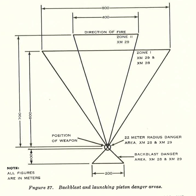
FIGURE 37.
(2) For the light weapon-
(a) Before each XM101 round is fired, the indexing tab is properly positioned in the key way slot.
(b) Plungers on rear legs of tripod are fully extended and legs are locked in position.
(c) Cross tube assembly is securely locked to both rear legs.
(3) For the heavy weapon-
(a) Correct propellant is loaded.
(b) Fins of projectile are not loose or damaged.
c. The loader makes certain --
1) For both weapon ·-
(a) The rubber gasket on the piston is not missing, torn, or improperly assembled.
(b) The pistons are free of surface cracks.
(2) For the light weapon-
(a) The front leg is firmly locked in position.
(b) Quick-release pins locking barrel to gimbal rings are fully seated.
53. Cartridge, Spotting, 20-MM, XM 101
The following safety precautions will be observed with the 20-mm spotting cartridge:
| a. | If the fuze safety wire is removed and the fire mission is cancelled, the safety wire can easily be replaced and the cartridge is safe and reusable. |
| b. | If the cartridge is dropped while the safety wire is removed, the following precautions will be taken: (I) All personnel will remove themselves from the immediate vicinity of the cartridge for a minimum of 2 minutes. Caution: After dropping, under no condition will the cartridge be touched. |
(2) After the waiting period has taken place, if the safety, wire can be inserted, the cartridge is safe and can b , reused. If the safety wire cannot be inserted, the car ridge is not drop safe and should be reported to explosive ordnance disposal unit in accordance with existing regulations.
54. Elevation Limitations, XM28
The light weapon is safe to fire only if the front leg is positioned as follows:
| a. | 350 to 660 mils-front leg extended to halfway position. |
| b. | Above 660 mils-with commanded elevation on sight unit, lower elevation to last mark on elevation tube, adjust front leg until elevation bubble is almost level, using elevation level bubble. |
| c. | Below 350 mils-lower the front leg six inches below the halfway position. |
55. Injury to Personnel or Damage to Material
Reports necessary to comply with requirements of the Army safety program are prescribed in detail in AR 385-40. These reports are re- . quired whenever accidents involving injury to personnel or damage to equipment occur.