Donate
| CHAPTER 4. | MARKSMANSHIP |
| Section I. | General |
| Section II. | Operation of sight unit. |
| Section III. | Weapons system alignment and sight calibration |
| Section IV. | Laying weapon for direction |
| Section V. | Technique of fire |
| Section VI. | Fire records |
Section I. GENERAL
71. General a. Doctrine requires timely and accurate delivery of fires to meet requirements of supported units. Members of Davy Crockett teams must be indoctrinated with a sense of urgency, and every effort made to reduce time required to execute an effective fire mission. Delivery of effective fire must not be sacrificed for other considerations. b. In order to inflict a maximum number of casualties, the immediate objective is to deliver accurate and timely fire. The number of casualties inflicted in a specific target area can be increased in most instances by surprise fire.
72. Indirect Fire a. Squads. Davy Crockett squads emplace weapons in defilade or partial defilade so they cannot be seen or easily located by the enemy. Since this measure precludes sighting the weapon directly at most targets (direct fire), another method of pointing the weapon (indirect fire) is used. Use of indirect fire requires coordinated efforts of all members of Davy Crockett squads, including squad leader, No. 1 (gunner), No. 2 (assistant gunner), No. 3 (loader), and No. 4 (computer). These elements are interconnected by wire and/or radio communication. Thorough and detailed training of all elements of the Davy Crockett squad is essential. b. Observers. Observers detect and report locations of suitable targets to the computer, and request fire. Observers are located so they have surveillance of the zone of action. Except when observing from aircraft or operating without computer, the observer adjusts fire along OT (observer-target) line. Normally, he does not need to know location of weapon. c. Computer. The computer determines firing data and issues fire commands to gunner and assistant gunner. d. Gunner, Assistant Gunner, and Loader. The gunner and his assistants load weapon and apply firing data to weapon and ammunition for laying and firing.
73. Elements of Firing Data
a. General. Information necessary to point (lay) the weapon is termed firing data, and includes direction and range. This data may be obtained by computation, estimation, or graphical means, based on location obtained by observation (visual or electronic) or by map or photographic analysis. The computer converts firing data to fire commands transmitted to the weapon.
b. Measurement. The principal unit of angular measurement is the mil; ranges and distances are measured in meters.
c. Direction. Direction is determined graphically, by computation, or estimation, and is expressed in mils.
(I) Deflection. The horizontal clockwise angle from line of fire to designated aiming point is deflection (fig. 43). A deflection set on the sight will cause the weapon to be pointed in the desired direction when traversed to the point where the sight is alined on the aiming post. Shift from initial direction is made by setting a new deflection on sight, then traversing the weapon to bring the sight back into alinement with the aiming post or reference line established by the aiming posts. The deflection normally is determined from the M16 plotting board to the nearest mil.
(2) Azimuth. The map can also be used to determine azimuths between points on the map. Azimuths on which the gun is to be mounted are determined by measuring azimuth from gun position to target. A semicircular protractor (mils) determines azimuths between points, or plots reported by azimuth and distance.
d. Angle-of-Site and Height-of-Burst. Altitude is vertical distance or elevation of a point relative to sea level. For marksmanship purposes, height-of-target in relation to gun and height-of-burst are important.
(I) Angle-of-site. Angle-of-site is the vertical angle between the target and a horizontal plane through the weapons (fig. 44), and is usually expressed in mils. For direct fire, the angle-of-site can be measured with the angle-of-site device provided with the sight unit (4, fig. 39). For indirect fire, angle-of-site must be computed. This can be done by determining the height of the target with respect to the weapon by the use of maps, or by reference to points of known altitude. Altitude of target and weapon is determined by use of contour intervals on a map. Difference in altitude is determined by taking the difference between the altitude of the weapon position and the altitude of the target. (If target is higher than the weapon, difference is plus. If target is below the weapon, the difference is minus.) Gun-target range is then read directly from the map, the WORM formula applied, and the angle-of-site expressed in mils. Example: At a map measured range of 2,000 meters, the target was computed to be 60 meters higher than the gun position. By use of the WORM formula, we compute:
W/R = M = 60/2 = 30 Mils , or angle-of-site of 30 mils.

FIGURE 43 - Deflection
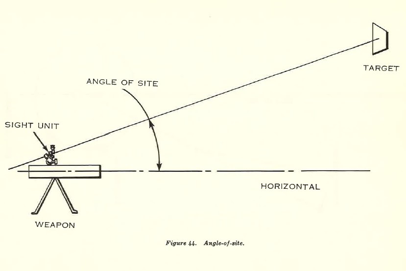
FIGURE 44 - Angle of site
(2) Height-of-burst (HOB). The HOB is vertical distance from ground or target to point of burst.
e. Range. Range is the distance between weapon and target, and can be determined by map or estimation. The range at which the weapon is fired is determined by measuring the map distance from firing position to target, or reading the range from the plotting board. Range is read to nearest 25 meters.
74. Theory of Target-Grid Method
a. The target-grid method (plotting board) of fire control simplifies procedure for controlling fire. An observer who has communication with a squad can adjust fire.
b. Using the M16 plotting board, the computer plots observer's corrections and determines firing data. Computer need not know observer's location. With the M16 plotting board, firing data corrections are made by converting OT (observer-target) line data to GT (gun-target) line data.
75. Observed and Unobserved Fires
a. General. Fire which can be observed is adjusted on the target. The observer who conducts the fire mission reports the effect of fire on target when the mission is completed. If possible, registration should always be fired and correction applied to this firing data. In the absence of specific corrections for the weapon, corrections determined by registration of another weapon can be used.
b. Communication. Communicatio1i between computer and forward observers is by radio or telephone. When practical, the telephone is used. All members of a Davy Crockett section must have a working knowledge of radio and telephone communication equipment, including radiotelephone procedure.
76. Targets
a. Davy Crockett weapon targets may be located and reported by organic observers, higher headquarters (from air and ground reconnaissance agencies), analysis of photos and knowledge of enemy activity, and interrogation of prisoners of war and civilians. The search for nuclear targets is constant and vigorous.
b. All supporting fires must conform to the scheme of maneuver of the supported unit(s). Once action is started, the Davy Crockett weapon fires as directed.
77. Fires
a. Prearranged Fires. Those fires prepared in advance are called prearranged fires. As the need .can be foreseen, fires are prearranged. These fires are delivered on schedule or on call.
b. Scheduled Fires. A schedule consists of a number of concentrations fired in a definite sequence. The time of starting may be "on call." For identification, a schedule may be known by a code name.
c. Fire Plans. For information on fire plans, including preparatory fires and defensive fires, see FM's 6-18 and 6-20.
d. Use. Prearranged fires support attack or defense and are also used during periods of poor visibility. They may be unobserved fires. N umbered concentrations should be assigned prominent terrain features, likely avenues of approach, possible assembly areas, known enemy positions, crossroads, road junctions, stream crossings, and prominent landmarks such as buildings and separate clumps of trees. These features are easily identified by observers who use them to help locate less prominent points. The location and number of these concentrations should be furnished those concerned with the adjustment of fire.
e. Planning Fires. Prearranged fires are used whenever feasible. Tentative plans for these fires may be made, but they must be coordinated with the general plan of operation or support. f. Preparing Data. The data for prearranged fires is placed on data sheets. Written data for prearranged fires is recorded at the weapon on a data sheet with entries so arranged that the computer can announce commands in proper order by reading from the data sheet.
78. Final Protective Fires
a. In the defense, each weapon is laid on its priority concentration when not otherwise engaged. This concentration is fired on prearranged signal or on call from the supported unit, and is re-fired when required.
b. Whenever possible, data for priority defensive concentrations should be confirmed by firing of verification rounds.
SECTION II. OPERATION OF SIGHT UNIT
79. General
a. Attaching the Sight. Insert male dovetail bracket of the telescope mount into female dovetail bracket of the telescope mount holder. When the sight is fully seated, a latch snaps into place and secures its position.
b. Checking Seat of Sight. Check seating of sight in dovetail bracket each time it is placed on weapon. Failure to check may cause waste of time and ammunition, as true angles of elevation set on the sight can be laid on the weapon only when the sight is securely latched. To see the sight is properly seated, grasp telescope mount and try to lift it out of dovetail bracket. If sight is properly mounted, the hook on the locking device engages a notch in the female dovetail bracket and the sight remains firmly in place.
c. Gunner's Position. After mounting weapon and attaching sight, assume standing position on the left side of weapon from which sight and weapon can be easily manipulated. The elbow telescope may be moved to horizontal or vertical position as desired by aligning index lines of telescope and telescope support. This insures the cross lines of the telescope reticle are in true horizontal and vertical positions.
d. Setting Azimuth or Deflection.
(1) To place azimuth or deflection setting on the sight, turn the azimuth knob which operates both azimuth and deflection scales and azimuth and deflection micrometer scales. All scales must be correctly set to obtain desired azimuth or deflection. For example, to place a reading of 3,775 mils on the azimuth scale, turn azimuth knob until fixed index opposite the moving azimuth scales is between the 3,700- and 3,800-mil marks (every fourth 100-mil graduation on azimuth scale is numbered O to 6,400) and the 75-mil mark on azimuth micrometer scale is opposite the fixed index. Use care to prevent making a 100-mil error; for example, setting micrometer at 75 mils and fixed index opposite moving azimuth and deflection scale between 3,600- and 3, 700-mil marks instead of between 3, 700- and 3,800-mil marks, would cause a 100-mil error.
(2) Setting of data on the sight does not change the direction of weapon. It moves the vertical line of the telescope sight off (right) (left) the aiming line. The data placed on the sight is announced in mils in the fire command. Azimuth or deflection data is placed on the sight before elevation data.
e. Setting the Elevation.
(1) To set the sight for elevation, turn elevation knob which - operates both elevation scale and elevation micrometer scale. Both scales must be properly set to obtain desired elevation. For example, to place an elevation of 550 mils on the sight unit, turn elevation knob until fixed index opposite the moving elevation scale is between the 500- and 600-mil mark on elevation scale (every 200-mil graduation is marked from Oto +800 and 0 to -300) and the 50-mil mark on elevation micrometer scale is opposite fixed index.
(2) Placing elevation on the sight unit does not change elevation of the weapon. The elevation in mils is announced in the fire command.
f. Removing the Sight. Before returning the sight to its carrying case, set elevation scale and micrometer at 0, azimuth scale and micrometer (red) at 3,200, deflection scale and micrometer at 0, and angle-of-site and micrometer at 0. Place elbow telescope in horizontal position. Depress locking device and remove sight unit from telescope mount holder. Turn eyepiece to left horizontal position and place in carrying case with elevation knob up, and then close the cover.
80. Sight Setting
a. Direct Fire. In direct fire, the sight is mounted with 3,200 mils on the azimuth scale, zero elevation, and zero angle-of-site on respective scales. Firing data (designation of target and elevation) is received from the squad leader or computer in the form of fire commands. The target is identified. The gunner lays the weapon on target in azimuth, using open sight and traversing mechanism. The sight unit is leveled by rotating elevating knob and cross-leveling hand grip. By rotating angle of site knob and traversing mechanism, the cross line of the elbow telescope is placed on the target. The gunner reads and announces angle-of site from angle-of-site scale and micrometer. When elevation element of the fire command is announced, the gunner places this on the sight unit. He turns elevation knob until the correct 100-mil elevation mark appears opposite elevation scale index. He continues to turn elevation knob until the remainder of the elevation reading appears opposite elevation micrometer scale index. After placing correct elevation on the sight, the gunner relays using elevation and traversing mechanism. With the vertical cross line on the target, he checks the elevation and cross-level bubbles and if necessary, re-levels.
b. Indirect Fire. In indirect fire, firing data (deflection and elevation) is received from the computer in the form of fire commands. Deflection element of the fire command normally comes first. The gunner places deflection and elevation on sight unit as described in paragraph 79d and e. After placing elevation on the sight unit, the gunner, by manipulating gun traversing and elevating mechanisms and cross-level hand grip, lays on the aiming post with elevating cross-level bubbles centered in vials
81. Aiming Line
a. Two aiming posts are provided to establish aiming or reference lines. These posts are placed on a line from the weapon position. The far aiming post is out approximately 100 meters and the near post is approximately 50 meters away. (In all cases, the near aiming post must be approximately halfway between weapon and far aiming post.) Use of two aiming posts reduces error caused by large deflection shifts or movement of tripod mount during firing.
b. When weapon is laid for direction, the gunner sees aligned sight picture shown in figure 45. The vertical cross line is laid on left edge of near post (far post obscured by near post and the two posts appear as one) . If they do not appear as one, displacement of sight has occurred and is compensated for as discussed in paragraph 83. c. When objects other than aiming posts are used as aiming point, place vertical cross line on some clearly defined point on object. When no clearly defined point exists on the object, use left edge of the object as aiming point.
82. Laying for Direction (Indirect Fire)
Since the computer knows the direction aiming posts are placed, he is able to give direction to target as angle of shift from them. The fire command contains exact deflection in mils to be placed on sight to shift
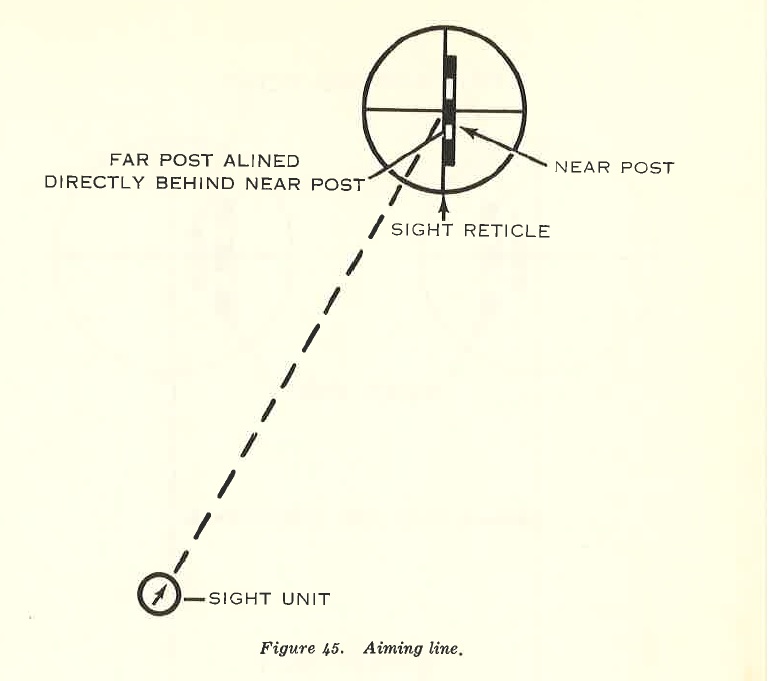
FIGURE 45 - Aiming line
weapon to desired direction. After placing deflection and elevation on sight, gunner looks through sight and sees that the vertical line on sight reticle has shifted away from aiming posts. He traverses to realign the vertical line and get exact adjustment, then checks cross-level vial, and (if necessary) levels bubble by rotating cross-level hand grip. If this adjustment moves the vertical line off the aiming posts, the gunner traverses until vertical line is again laid on aiming post. He repeats above procedure as many times as necessary until vertical line of sight reticle is on left edge of aiming posts and cross-level bubble is centered. This lays weapon correctly for direction.
83. Displacement of The Sight
a. In laying for direction, the two aiming posts do not always appear as one when viewed through the sight. This separation is caused by one of two things: either a large deflection shift of the barrel or a lateral displacement of the tripod mount cau~d by shock of firing. b: When aiming posts appear separated, the gunner cannot correctly use either of them as an aiming point. For example, if he lays on the near post, the barrel will be a considerable distance to one side of the desired direction of fire.
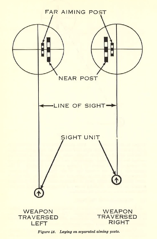
FIGURE 46 - Aiming line
c. To lay weapon correctly, the gunner must take a compensated sight picture. He must traverse the gun until the sight picture appears as shown in figure 46. He lays the vertical line of sight reticle so the left edge of the far aiming post. is exactly midway between the left edge of the near aiming post a.nd t he vertical line of sight reticle. This corrects for the displacement.
d. At first lull in firing, gunner determines if displacement is caused by traversing the gun or displacement of the tripod. To do this, place the referred deflection on sight and lay on aiming posts. If both aiming posts appear as one, separation was caused by traversing. In this case he continues to lay the gun as described and does not realign aiming posts. When making the check above, if posts still appear separated, the separation was caused by displacement of the tripod. The gunner requests permission to realign aiming posts. To realign, the gunner-
(1) Places on the sight the original deflection assigned the posts.
(2) Lays the weapon so vertical line of the sight reticle is aligned on left edge of far post.
(3) Without shifting the weapon, refers the sight until vertical cross line falls on left edge of near post. This measures the angle between posts.
(4) With this last deflection set on the sight, relays weapon until vertical cross line is aligned on far post.
(5) Without shifting weapon, refers sight again to original deflection on which posts were placed out. The line of sight, through the sight, is now parallel to the original line established by aiming posts.
(6) Looking through sight, directs No. 2 to move posts so they are realigned with sight's vertical cross line. Posts are now realigned to correct for displacement. This procedure is followed only if displacement causes difficulty in laying for direction.
SECTION 111. WEAPONS SYSTEM ALINEMENT AND SIGHT CALIBRATION
84. General
a. Accurate marksmanship with the Davy Crockett weapons system depends upon crew skill and techniques; however, certain fundamental adjustments must be made in the system before crew manipulations become important. These adjustments, upon which accurate marksmanship also depends, are correct alignment of the system and proper calibration of the sight.
b. With the light weapon, proper alignment between axis of bore of the barrel, axis of bore of the spotting rifle, and axis of line of site must be made before the crew can hit a target. With the heavy weapon, only two axes must be aligned; the axis of bore of the barrel and the axis of line of site.
85. Bore sighting (Distant Aiming Point Method)
Bore sighting, as the alignment procedure is called, results in the axis of bore of the heavy weapon barrel and the axis of line of site converging on the same distant point. With the light weapon, the result is the same except that, in addition, the axis of bore of the spotting rifle converges on the same distant point as the other two axes. The procedure is as follows:
a. Number 2, the assistant gunner-
(1) Places muzzle bore sight (fig. 47) across opposite bore sight notches on barrel. Point of intersection marks axis of bore at muzzle.
(2) Manipulates elevating and traversing hand wheels as directed by number 1, the gunner.
b. Number 1, the gunner :
(1) Inserts breech bore sight (fig. 48) into nozzle of barrel. The Ysinch aperture marks axis of bore at nozzle (breech) of the weapon.
(2) Sets azimuth scale (red) at 3,200 mils.
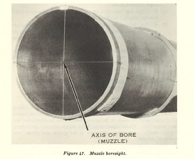
FIGURE 47 - Muzzle bore sight
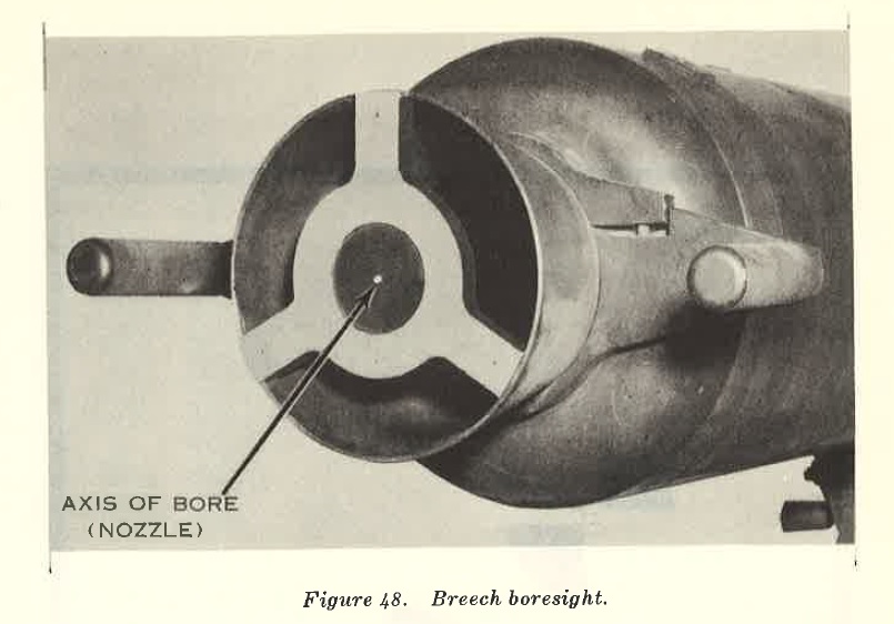
FIGURE 48 - Breech bore sight
(3) Rotates cross-level hand grip until scribe line is barely visible.
(4) Places muzzle bore sight in muzzle of spotting rifle (light weapon only).
(5) Selects aiming point about 2,000 meters from weapon. This minimum distance is necessary to limit the parallax error.
(6) Aligns axis of bore of the weapon on distant aiming point by directing number 2 in manipulation of elevation and traversing mechanism.
(7) Aligns cross line of muzzle bore sight on distant aiming point by rotating elevation and azimuth rings inside spotting rifle mount (light weapon only).
(8) Aligns cross line of elbow telescope on distant aiming post by rotating elevation and azimuth knobs on the sight.
(9) With all the cross lines laid identically on the same distant aiming point, the gunner checks to see he has an azimuth reading of 3,200 on his azimuth scale and O on his azimuth micrometer. If not, the sight is adjusted as follows:
(a) Loosen the two screws on the top of the azimuth scale.
(b) Rotate the azimuth scale until 3,200 mils is opposite the index mark.
(c) Tighten screws.
(d) Loosen screws in azimuth knob.
(e) Without moving other parts of the sight, move the azimuth micrometer scale until it reads zero.
(f) Tighten screws.

FIGURE 49 -
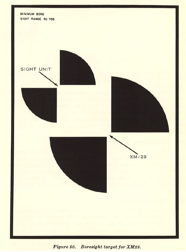
FIGURE 50 - Bore sight target for XM29

FIGURE 51 - Bore sight XM28
c. When the azimuth micrometer scale is set on zero, t~~ muth scale is set on 3,200 mils, and all cross lines are identically on same distant point, the weapon is bore sighted.
d. When the bore sighting weapon is mounted on the carrier, every effort must be made to avoid movement of personnel on the carrier and shifting of the vehicle springs. To assure maximum accuracy, the weapon must be bore sighted on ground mount.
e. Accuracy of alignment is sufficient when axis of bore of spotting rifle, axis of bore of major caliber weapon, and axis of line of site are adjusted on aiming point within ½-mil tolerance.
86. Bore sighting (Tested Target Method)
A bore sight target may be used for bore sighting when distant aiming point method cannot be used. This target permits alignment of sight and weapons at a minimum distance of forty meters. The target is issued with the weapon and consists of three sectors (aiming points) for the light weapon (fig. 49) and two for the heavy weapon (fig. 50). Using the bore sight target, procedure for bore sighting is same as described in paragraph 85 (fig. 51);
87. Sight Calibration
a. Sight must be calibrated to the weapon on which it is to be mounted. This is necessary because the dovetail slot which receives the sight unit is a machined part and will vary in accuracy with each weapon. There is no set rule for frequency of calibration. The time available and accuracy desired will determine frequency of calibration.
b. When a check indicates the sight is out of calibration, have it recalibrated by a qualified individual (squad leader or a designated individual trained in calibration procedure). The sight is calibrated first for elevation and then for deflection.
c. To effect calibration of the sight, each weapon is provided with aiming circle and gunner's quadrant. Instructions for use of these are contained in FM 23-92.
d. Procedures for calibrating the sight are the same for both the light and heavy weapon unless otherwise indicated.
e. To calibrate elevation scale-
(1) Mount weapon on level ground.
(2) Center elevation mechanism on cross tube assembly (light weapon only).
(3) Set elevation of 500 mils on gunner's quadrant and on sight unit; place gunner's quadrant on machined surface of weapon and center bubble in level vial.
(4) Cross-level the sight by turning cross-level hand grip and elevation knob.
(5) If the reading on elevation scale is not the same as the reading on gunner's quadrant, take the following action:
(a) Loosen screws in elevation knob.
(b) Keeping elevation bubble centered in elevation level vial and without turning elevation knob, rotate elevation micrometer scale to zero.
(c) Tighten screws in elevation knob.
(d) Loosen screws on the elevation scale.
(e) Slide elevation scale until 500 mils is opposite the index mark.
(f) Tighten screws on the elevation scale.
(g) Recheck readings of gunner's quadrant, elevation micrometer scale, and elevation scale. If different, repeat above procedure until both instruments read the same with bubbles centered in level vials.
f. There are four methods for calibrating sight for deflection, the aiming circle method, bore sighting (par. 85), bore sighting (tested target, par. 86), and the distant aiming point method (aiming circle).
(I) Aiming circle method-
(a) Mount weapon on level ground.
(b) Center elevating mechanism on cross tube assembly (light weapon only).
(c) Set up aiming circle 25 meters to rear of weapon and in line with barrel.
(d) Place breech bore sight in nozzle of weapon.
(e) With azimuth scale and micrometer scale of aiming circle at 0, aline vertical line of aiming circle on center of .Vs-inch aperture in breech bore sight.
(f) Traverse and cross-level weapon until center axis of barrel from nozzle to muzzle is aligned with vertical line of aiming circle (fig. 52).
(g) Turn azimuth knob of sight until vertical line is centered on lens of aiming circle; read angle A (fig. 53) opposite azimuth micrometer index.
(h) Turn azimuth knob of aiming circle until vertical line of telescope is laid on center of sight lens; read angle B (fig. 53) opposite azimuth index.
(i) If sight is in calibration, angles A and B are equal. If not, sight is adjusted as follows:
1. Loosen screws in azimuth knob and azimuth scale.
2. Without moving other parts of sight, move azimuth micrometer scale until it reads the same as angle B.
Note. If sight, weapon, or aiming circle is moved during calibration, repeat entire procedure.
3. Tighten screws in azimuth knob and azimuth seale.
(2) Distant aiming point method-
(a) Set up aiming circle and aline vertical line on distant aiming point, preferably in excess of 2,000 meters (set azimuth on 0).
(b) Mount weapon on level ground 25 meters from aiming circle and on line between aiming circle and distant aiming point.
(c) Center elevating mechanism on cross tube assembly (light weapon only).
(d) Cross-level sight by turning cross-level hand grip.
(e) With vertical line of aiming circle still laid on distant aiming point, move weapon tripod until ½-inch aperture of breech bore sight is aligned with vertical line of aiming circle. Traverse and cross-level barrel until axis of tube at nozzle and muzzle is aligned with vertical line of aiming circle.
(f) Lay vertical line of the sight unit on the same distant aiming point. Sight should then read O on the azimuth micrometer scale and 3,200 on the azimuth scale. If it does not, take the following action:
1. Loosen screws in azimuth knob.
2. Without turning the azimuth knob, rotate azimuth micrometer scale to 0.
3. Tighten screws in azimuth knob.
4. Loosen screws on the azimuth scale.
5. Rotate the azimuth scale so the figure 3,200 appears opposite the index mark.
6. Tighten the two azimuth scale retaining screws.
88. Angle-of-Site Calibration.
To calibrate the angle-of-site device, the procedure is as follows:
a. Calibrate the sight unit for elevation as outlined in paragraph 87. Place the muzzle and breech bore sight devices on the major caliber barrel. Lay the axis of the major caliber barrel on a distant aiming point and level the elevation bubble by turning the elevation knob. Note the reading on the elevation and elevation micrometer scales. Lay the elbow telescope on the same distant aiming point as the major caliber barrel by turning the angle-of-site knob.
b. Note the reading of the elevation and angle-of-site scales; if they are the same, the angle-of-site device is calibrated. If the elevation and angle-of-site readings are different, proceed as follows:
(1) Without moving the weapon or sight unit, loosen the screws on the angle-of-site scale and the screws in the angle-of-site knob.
(2) Move the angle-of-site scale and angle-of-site micrometer scale until they read the same as the elevation scale and elevation micrometer scale. Tighten the screw in the angle-of-site knob and on the angle-of-site scale.
(3) Recheck the alignment of the barrel and elbow telescope on the distant aiming point. If laid properly, the angle-of-site device is calibrated. If the barrel and elbow telescope are not laid properly on the distant aiming point, repeat the entire calibration procedure above.

FIGURE 52 - Aligning center axis of barrel with vertical line of aiming device

FIGURE 53 - Determining angles A and B
SECTION IV. LAYING WEAPON FOR DIRECTION
89. General.
Both light and heavy weapons are laid for direction in the same manner. a. To place fire on or near a target, location of target relative to firing position must be known. Basic initial data required consists of direction and range. When there is a difference in altitude (angle-of-site) between target and weapon, that data is also required. This basic data is used to calculate firing data enabling the squad to lay weapon correctly so first spotting round will burst on or near target. b. A thorough knowledge of map and aerial photograph reading is essential for aU leaders, observers, and computers. This information is contained in FM 21-26.
90. Determining Range The distance (range) from weapon to target should be determined as soon as possible after firing position has been selected. There are numerous methods of determining this range. a. Estimation by Eye. The accuracy of this method depends on ability and experience of the individual. b. Measurement. When accurate maps are available, ranges may be measured from the map.
91. Determining Direction.
The computer determines initial direction for mounting weapon in indirect fire. The direction of target is transmitted to the gunner as deflection. The observer designates location of target by sending to the computer the azimuth of target from his position and shift in meters from terrain reference point located by the computer. He may give its coordinates from map or photo map by giving geographic direction and distance from known point or by azimuth and distance from the observer(s) position. In special situations, it may be necessary for observer to determine direction of target from weapon. Some of the most commonly used methods are discussed in paragraphs 92 through 94. In general, the simplest usable method is preferred.
92. Determining Initial Data With Map.
a. General. When accurate maps or photo maps are available, obtain direction of fire and gun-target range by use of the map or photo map. A protractor or compass, and some means of measuring map distance is required. This method is simple, rapid, and accurate. It is used whenever location of weapon and target are known. b. Position Locations. To obtain accurate map data, know map location of weapon and target. Points on the ground can be located rapidly by inspection; however, a knowledge of map reading is essential. In locating the weapon on the map, use terrain features and terrain contour to the maximum. In locating registration point or checkpoint, use prominent terrain features like road junctions, bridges, buildings, etc., to eliminate errors in initial data. c. Map and Protractor Method (fig. 54) . Locate target and weapon positions on map and draw GT (gun-target) line between these points. Measure azimuth of line by placing index of protractor at intersection of GT line (extended when necessary) and any vertical grid line, and then read the clockwise angle from grid north to GT line. Measure GT range from map between the points, using any measuring device having the same scale as that of the map. d. Map and Compass Method (fig. 55) . Locate target and weapon position on map and draw line· connecting the points. Place map on flat surface and orient it by placing zero of grid-declinated compass to coincide with north-south grid line of map, and by rotating map until compass needle is centered opposite north. With map oriented, lift compass and place it so its zero line is on grid-target line. The needle indicates grid azimuth of grid-target line. Range is again measured as described in c above.
93. Determining Initial Data With M 16 Plotting Board.
The M16 plotting board method of determining initial data is satisfactory when accurate maps are not available. The observer must know general location of weapon. He determines azimuth and range to weapon and to target. This method is illustrated in the following example: a. The observer transmits this data to the computer (1) OP to weapon: azimuth 4,150 mils range 550 meters. (2) OP to target: azimuth 5,750 mils range 1,500 meters. b. Using range scale along index line, determine range and azimuth from weapon to target as follows: (1) Rotate disk until 4,150 mils is read over index mark on base. Mark pencil dot over index line at 550-meter graduation. This dot represents location of weapon. (2) Rotate disk until 5,750 mils is read over index mark on base. Mark pencil dot over index line at 1,500-meter graduation. This dot represents location of target. (3) Rotate disk until imaginary line connecting pencil dots is parallel with index line and with dot representing location of target toward index arrow. (4) Read gun-target azimuth at index mark (6,110 mils). The total number of meters between pencil dots when in parallel position (1,400 meters above horizontal grid line passing through pivot point, plus 200 meters below), is gun-target range (1,600 meters).
94. Determining Initial Data By the Parallel Line Method Determining initial data by parallel line method is simple and rapid. As an observer, estimate the shortest distance from your position to GT (gun-target) line. Select an object on the ground which is on same side of GT line and at the same distance you are from line. With a compass, read azimuth from your position to selected object. This is azimuth of GT line. For example (fig. 56), observer at point O estimates shortest distance to GT line as 125 meters. He then selects some object in front of him that is 125 meters from gun-target line. Such point in this case would be on line OX. Azimuth of line XO, therefore, is same as azimuth of line GT. Initial GT range is determined by estimation.

FIGURE 54. Map and protractor method.
95. Laying the Weapon
a. Aiming Circle Method. The aiming circle, M2, is the primary means used to lay both weapons for direction. Normally, they are laid on a grid mounting azimuth as determined by the computer; however, a magnetic mounting azimuth could be used in special situations. For the procedure of laying the weapons on a grid or magnetic azimuth, see FM 23-92. b. Compass Method. The compass, M2, is the secondary means used to lay both weapons for direction. This method is particularly valuable
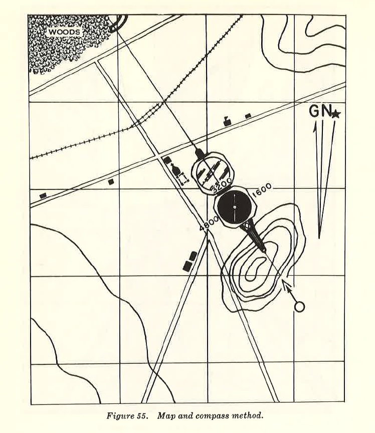
FIGURE 55. Map and compass method.
when speed is essential or the aiming circle is not available. The mounting azimuth is obtained as indicated in paragraphs 92 and 93. The gunner marks position of weapon by driving position stake in ground. A compass is placed on stake and rotated until azimuth desired is established on mil scale. Caution: Weapon and other metal equipment must be at least 10 meters from compass. He directs number 2 man to place direction stake on this azimuth at least 25 meters from weapon position. The weapon is mounted with the sight unit directly over position stake. With 3,200 mils on azimuth scale (red), vertical line of sight reticle is laid on left edge of direction stake. c. Alternate Compass Method. This method is used in crew drill or as a substitute for b above. The gunner stands about 10 meters to the rear of the weapon and sights through his compass on the mounting azimuth desired. He directs the weapon to be moved until the barrel is exactly centered on the line of site through his compass. The gunner now shifts his line of site to the sight unit, while keeping the line of site parallel to the barrel. A direction stake is now emplaced 25 meters in front of the weapon and so that its left edge is on the compass line of site. A reading of 3,200 is set on the azimuth (red) scale, and the vertical cross line of the sight unit is laid on the left edge of the stake. d. Direct Alignment Method. This is an expedient method of laying the weapon when the aiming circle or compass methods cannot be used. The forward observer places himself on the gun-target (GT) line so that he can see both the target and weapon. The position of the observer or the weapon (or both) must be adjusted until the weapon, observer, and target are in a straight line. The gunner now sets 3,200 on the azimuth (red) scale and lays on the forward observer. The weapon is now laid for direction on the target. e. Direct Lay Method. This method is used in situations where speed in destroying the target is more essential than cover. This type firing position is occupied temporarily and evacuated as soon as target is destroyed. To use this method, the target must be visible to the gunner when looking through the sight. The cross line of the sight reticle is laid on target.
96. Referring the Sight.
a. Referring the Sight. This is to make a deflection change on the sight without disturbing the lay of the weapon. To refer the sight, turn azimuth knob until given deflection is set, or until the cross lines of the sight are laid on given point. b. Placing Out Aiming Posts. Two aiming posts are placed out in order to establish a reference line from which changes in direction can be made. The approximate right flank of the weapon is the ideal location for the aiming posts. If the posts are placed to the left flank of the weapon, the gunner's body may obstruct the line of site. The line of site will also be frequently obstructed by the barrel if the aiming posts are emplaced to the front. Since the weapon has a characteristic back blast, aiming posts should not normally be placed out to the rear. To place out aiming posts, the assistant gunner takes both posts, moves approximately 50 meters to the right flank of the ·weapon, and drops one aiming post. He then continues out to approximately 100 meters from the weapon and emplaces the other aiming post. The gunner now refers his sight until the vertical cross line of the elbow telescope is laid on the point
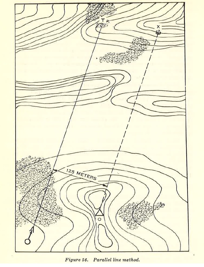
FIGURE 56. Parallel Line method
where the post enters the ground. The gunner directs the assistant gunner by arm-and-hand signals to lean the top of the post right or left so the entire left edge of the post is aligned on the cross line. While the assistant gunner moves in to the near post, the gunner slips the deflection scale and micrometer scale (black scale) to read 3,200. The assistant gunner now positions the near post by direction from the gunner. It is emplaced when the bottom of the post is aligned on the cross line of the sight. The top of the post is leaned right or left in the same manner as with the far post. The left edges of both posts are now aligned on the vertical cross line of the sight. The far post will be obscured from view since the near post is directly in front of it. Note that the deflection setting on the sight was not disturbed after the scales were slipped to the referred deflection of 3,200. Deflection scale may be slipped to 3,200 mils after both posts have been emplaced. If the tactical situation does not permit placing out and aligning aiming posts, a natural object with a clearly-defined vertical edge may be used as a substitute for the aiming posts.
SECTION V. Technique of Fire
97. General
a. Simple References for Davy Crockett Usage. (1) Technique of fire. Methods for placing effective fire on target. (2) Direct laying. Laying on a target visible to gunner through the sight. (3) Direct fire. Firing conducted when direct laying is used. (4) Indirect laying. Laying on a target not visible to gunner. (5) Indirect fire. Firing conducted when indirect laying is used. b. Characteristics of Fire. Both light and heavy weapons are classified low angle fire weapons. They may be laid for direction either direct or indirect. c. Range Determination. (1) Length of time available to fire from direct fire position is in many cases limited; therefore, quick and accurate determination of range is extremely important. (2) The spotting round is the primary method of determining range for light and heavy weapons. The two spotting rounds used are- (a) Light weapon-20-mm spotting round XMlOl. (b) Heavy weapon-projectile, atomic, super caliber, 279-mm, practice, XM390. d. Forward Observer Procedure. (1) The target-grid method of adjustment is used with light and heavy weapons when firing indirect fire. (2) Direct fire is normally adjusted by the squad leader or computer. (3) Detailed instructions for target-grid method of adjustment are contained in FM 23-92.
98. Fire Commands
a. General.
(1) Fire commands are instructions issued to enable the squad to engage the target. (2) There are two kinds of fire commands, initial and subsequent. Initial fire commands include all data necessary for laying, loading, and firing the weapon. Subsequent fire commands include commands issued to adjust, shift, cease, or suspend fire. They normally include only those elements necessary to accomplish these actions. (3) A correct fire command is as brief as clarity permits. It includes all elements needed to accomplish the fire mission and is given in logical sequence to accustom the squad to execute instructions in a definite order. It is transmitted at a rate that permits receipt and application of instructions without confusion. Unnecessary elements are omitted. (4) Fire commands are usually given orally. When oral delivery is not practicable, fire commands may be transmitted by telephone, radio, messenger, or arm-and-hand signals. (5) Numbers in fire commands are announced as illustrated in the following examples:
| lO | ____________ | ONE ZERO |
| 26 | ____________ | TWO FIVE |
| 300 | ____________ | THREE HUNDRED |
| 876 | ____________ | EIGHT SEVEN FIVE |
| 1,400 | ____________ | 0NE FOUR HUNDRED |
| 1,926 | ___________ | 0NE NINE TWO FIVE |
| 3,000 | ____________ | THREE THOUSAND |
| 4,060 | ____________ | FOUR ZERO FIVE ZERO |
(6) Each squad member repeats that portion of the fire command which pertains to him.
b. Sequence.
(1) The following sequence is prescribed for the initial fire command. Any of these elements that do not pertain to a specific fire command are omitted.
(a) Alert (b) Zone (c) Ammunition (HOB) (d) Direction (AZ, DEFL) (e) Target description (f) Range (g) Elevation (h) Time (i) Control (2) Example of fire commands for light or heavy weapons: (direct fire)
| INITIAL | SUBSEQUENT |
* The control element is not announced by the squad leader or computer until the gunner has applied the data to the sight and announced UP. At this time, instructions for firing are issued.
99. Direct Fire a. Direct fire procedure is the same for light and heavy weapon except as indicated. The squad leader or computer may issue the fire command. b. Light and heavy weapons can be fired from vehicle or ground mount except those stored in full-tracked personnel carrier M113. These can be fired from the ground mount only (par. 51l). c. To lay weapon for direct fire (ground or vehicle mounted) the procedure is as follows: (1) Firing spotting ammunition. As long as the ammunition element is not announced in the command, the crew will automatically fire spotting ammunition. The term "spotting" is not announced. The following orders are given and actions are performed by members of the squad: (a) The squad leader issues the following direct fire command: FIRE MISSION ZONE I (heavy weapon only) FRONT BRIDGE OVER RIVER ONE FIVE HUNDRED (b) Upon hearing ZONE portion of the order, the assistant gunner loads appropriate propellant (heavy weapon only) and assists in loading the launching piston. (c) Loader loads launching piston. (d) Assistant gunner assists in loading major caliber projectile (HE) on heavy weapon. On light weapon, after hearing TIME, he assists in loading major caliber projectile (nuclear), and loads spotting rifle. (e) After weapon is loaded, gunner takes the following action: 1. Sets azimuth scale (red) on 3,200 mils. (This aligns sight with axis of barrel.) 2. Sets elevation and angle-of-site scales and micrometer scales on zero. 3. Lays weapon for direction on target using open sight and operating traversing mechanism. 4. Centers elevation bubble by operating elevating mechanism and centers cross-level bubble by rotating cross-leveling hand grip. 5. Places horizontal cross lines of elbow telescope on target by rotating traversing mechanism and angle-of-site scale. 6. Reads angle-of-site on the angle-of-site scale. 7. Announces reading to computer as PLUS (MINUS) _ MILS. (f) The computer announces elevation to gunner in mils as ELEV A TIO N __ _____ ___ . (g) The gunner places announced elevation on sight, lays on target by operating elevating and traversing mechanism, levels cross-level bubble, and announces UP. (h) When ready to fire, squad leader commands FIRE. (i) The gunner fires. (j) Squad leader corrects heavy weapon for errors in range and deflection (with light weapon, range only). (k) Corrections are made until fire is adjusted on target with spotting round. (2) Firing nuclear ammunition. To fire nuclear ammunition, additional actions are required: (a) When firing light weapon, change in elevation must be made when changing from spotting round to nuclear projectile. This change compensates for powder temperature of major caliber propellant. (b) When firing the heavy weapon, no change in elevation is required for powder temperature since major caliber HE projectile is used for adjustment. (c) With either weapon, if projectile is to be detonated at a medium height burst, an additional step in computing elevation is required. It may be made concurrently with temperature computations. (d) When ready to fire, the gunner announces UP. (e) Upon hearing the command UP, all personnel move to a safe position. (f) The gunner rechecks bubble and unrolls LEDC to safe position. (g) Upon receiving command to fire, he removes safety pin from firing device and pulls firing ring.
100. Indirect Fire.
a. General. This procedure is the same for light and heavy weapon. The weapon is laid for direction, sight referred, and aiming posts are placed out (par. 81). b. Procedure. (1) Firing spotting ammunition. The following orders are given and actions performed: (a) Example of fire request (FO to computer): OP ONE FIRE MISSION COORDINATES, ONE TWO FOUR TWO THREE ONE ONE SEVEN AZIMUTH, ONE SEVEN THREE ZERO TROOPS IN ASSEMBLY AREA WILL ADJUST (b) The computer, using plotting board, determines initial deflection based on azimuth on which weapon is laid. A range is determined sufficient to place the first round in a position in target area where observer can see it. (c) When the computer determines deflection and elevation, he issues a fire command to the gunner. (d) Example of fire command (computer to gunner): FIRE MISSION ZONE I (heavy weapon only) DEFL~CTION, FIVE FOUR HUNDRED ELEVATION, EIGHT HUNDRED TIME, SEVEN POINT ZERO (light weapon only) (e) The gunner places directed data on the sight. He lays for elevation and deflection and then announces UP. (f) Procedure for firing is same as for direct fire, paragraph 99. (g) Forward observer corrects for errors in firing data by adjustment. The corrections which observer sends to computer are based on sensing of previous round. (h) Example of correction (FO _to computer): RIGHT, FIVE ZERO DROP, TWO HUNDRED (i) Using the plotting board, the computer determines new deflection and range. (j) New firing data is then given the gunner as a subsequent fire command. (k) Example of fire command (computer to gunner): DEFLECTION, FIVE FOUR TWO FIVE ELEVATION, SIX SEVEN FIVE (l) Procedure for laying gun and firing is same as above. Corrections are made until fire is adjusted on target. (m) The forward observer indicates adjustment on target is complete by requesting FIRE FOR EFFECT. (2) Firing nuclear ammunition. As described in paragraph 99, when changing from spotting rifle to nuclear projectile on light weapon, computer compensates for temperature in same manner as for direct fire.
SECTION VI. FIRING RECORDS
101. Computer's Record.
This record, DA Form 2498-R, (fig. 57) is a worksheet of data acquired during a fire mission. DA Form 2498-R will be reproduced locally on 8 x 10½ inch paper. Each computer uses a separate form for each fire mission. · He places assigned concentration number on record and keeps form as record of mission. This provides a record of each round fired and firing data for each concentration.
102. Computor's Data Sheet.
The computer's data sheet (DA Form 2499-R) (fig. 58) is used to consolidate information obtained and recorded on computer's records (DA Form 2498-R). It is used to record prearranged fire data. At end of each mission, the computer records concentration number and firing data on the computer's data sheet. This permits rapid retiring of any concentration. DA Form 2499-R will be reproduced locally on 8 x IO½ inch paper.
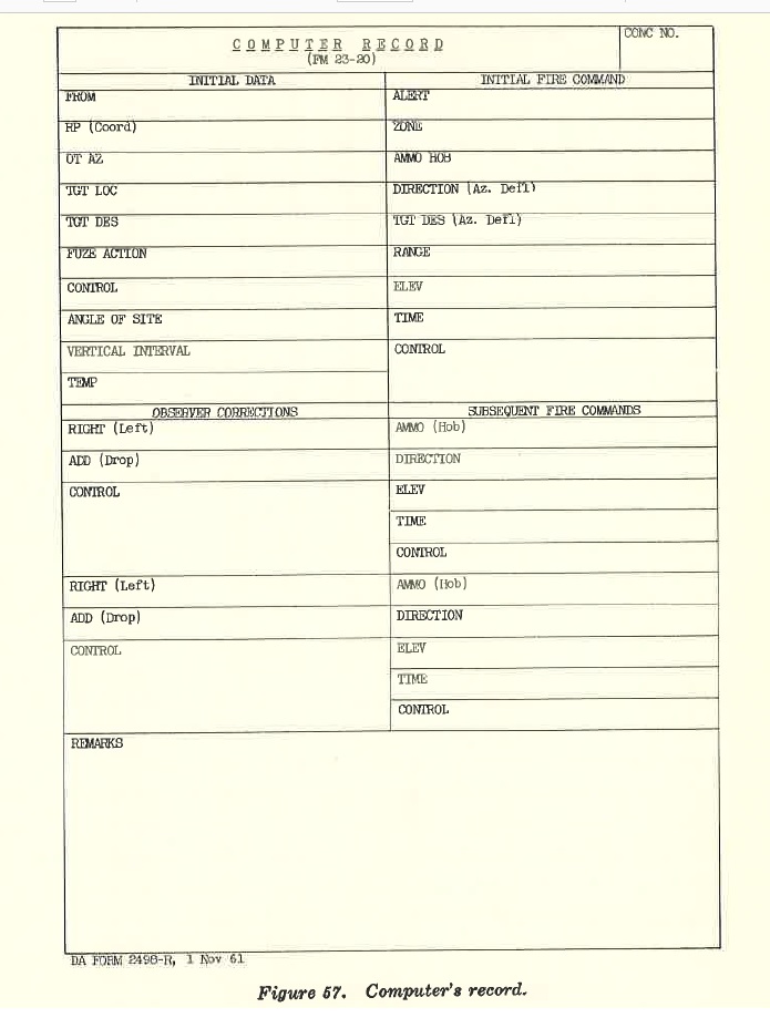
FIGURE 57. Computer's record
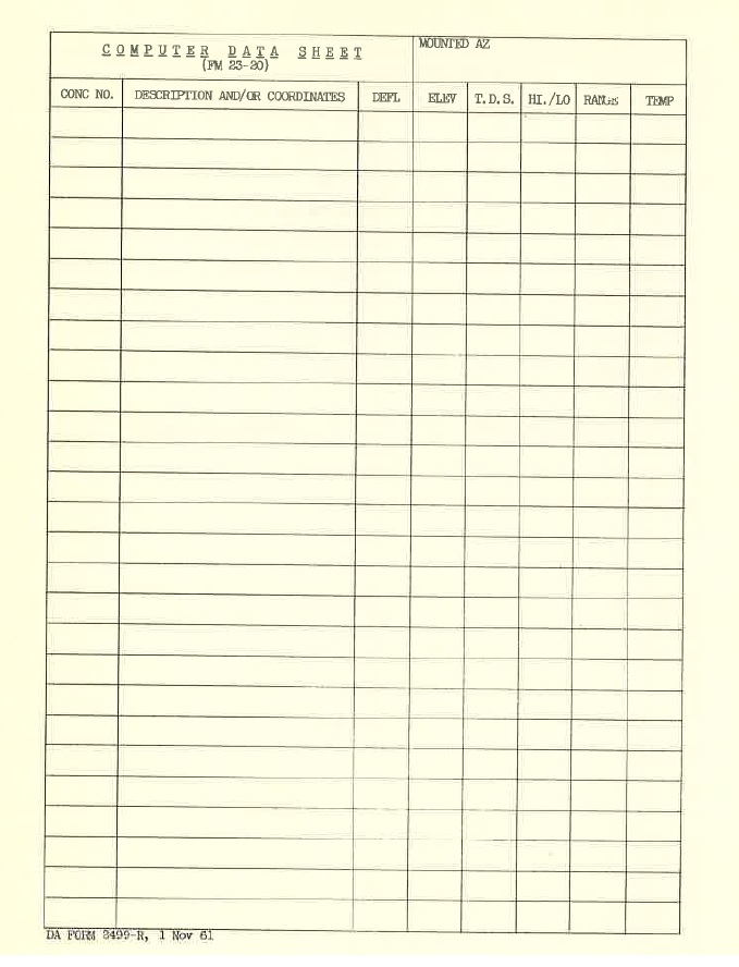
FIGURE 58. Computer's data sheet.