Donate
| CHAPTER 3. | FIRE CONTROL EQUIPMENT |
| Section I. | General |
| Section II. | Sight unit |
56. General a. Fire control equipment for direct and indirect fire is essentially the same for the light and the heavy weapon. The principal differences in equipment are found in ranges and temperature scales of firing tables, and size and type of bore sight equipment.
b. The firing control system includes the following equipment, used with the light and/ or heavy weapon as indicated:
|
57. TECHNICAL DATA
a. Elbow telescope XM107
|
b. Telescope Mount XM117 (less elbow telescope)
| Length | ---------- | 4 3/8 inches |
| Width | ---------- | 5 1/8 inches |
| Height | ---------- | 7 3/4 inches |
| Weight | ---------- | 4 lbs 10 oz |
c. Telescope Carrying case XM121
| Height | ---------- | 9 1/4 inches |
| Diameter | ---------- | 10 inches |
| Weight | ---------- | 4 pounds |
d. Bore sight Carrying Case XM120 and XM122
| Length | ---------- | 12 inches |
| Diameter | ---------- | 8 inches |
| Weight | ---------- | 3 pounds |
e. Telescope Mount Holder XM5 and XM6
| Length XM5 | ---------- | 6 5/8 inches |
| Length XM6 | ---------- | 7 1/8 inches |
| Width | ---------- | 2 1/2 inches |
| Height | ---------- | 2 inches |
| Weight | ---------- | 1 pounds |
58. Bore sight Equipment
a. Breech Bore sight XM47 and XM51 (fig. 38). Breech bore sight XM47 and XM51 are identical except for size. They are aluminum with a magnetic insert which holds the bore sight in the nozzle (breech) of the weapon. XM47 is used with light weapon, and XM51 with heavy weapon. The ½-inch aperture in center of breech bore sight indicates axis of bore at nozzle. The target is seen through aperture during bore sighting.
b. Muzzle Bore sight XM48 and XM52 (fig. 38). Muzzle bore sights XM48 and XM52 are identical except for size. Each is a red elastic garter-type band placed over muzzle end of barrel. Two cords cross forming 90° quadrants when the muzzle bore sight is tight. The point at which the cords of the muzzle bore sight intersect establishes an axis of bore at the muzzle. The XM48 is used with light weapon, and XM52 with heavy weapon.
c. Muzzle Bore sight XM50. The muzzle bore sight XM50 is a bright red, 3-power, fixed focus telescope instrument providing a line-of-site by which the spotting rifle is bore sighted. The reticle is a vertical and horizontal cross line. The telescope is fastened to an aluminum support. The support has a nut and a rod with a sleeve. The rod and sleeve are inserted into the bore of the spotting rifle barrel from the muzzle end. The bore sight then aligns the axis of bore of the spotting rifle with the axis of bore of the major caliber weapon and the axis of sight.
59. Plotting Board M 16 The M16 plotting board computes data for indirect fire for light and heavy weapons. The M16 plotting board is described and instructions for its use are given in FM 23-92.
60. Firing Tables Firing tables are provided for each weapon, are printed in card form, and included in ammunition packing container.
61. Aiming Circle M2 The aiming circle is used to lay the weapon for direction and calibration of the sight unit. Detailed instructions for its use are contained in TM 9--6166, FM 6-2, and FM 6-40.

FIGURE 38 - Bore sight equipment
62. Compass M2
The compass is used by the forward observer and gunner. Instructions for its use are contained in FM 23-92.
63. Gunner's Quadrant M 1 A 1
The gunners' quadrant is used to calibrate the sight unit. Instructions for its use are contained in FM 23-92.
64. Aiming Post M 1 A2
Aiming posts MIA2 are provided for each weapon. These posts establish a "reference line" or "aiming line" in indirect fire.
65. Aiming Post Light M 14
The aiming post light MI4 is used for night firing. It consists of a battery case with two flashlight batteries, a light bulb, and a switch. The light is provided with two colored filters (green and red), and a shaded hood. When the aiming post light is turned on, a thin green (red) light appears on the lens.
SECTION II. SIGHT UNIT
66. Elbow Telescope XM107
a. The elbow telescope XM107, telescope mount XMll 7, and telescope mount holder XM5 or XM6 are fastened together for operation (fig. 39). The elbow telescope provides a magnified optical line of sight by which the weapon is aimed. The telescope mount secures the telescope in position with respect to azimuth and elevation axes of the weapon. A male dovetail connects the telescope mount to the telescope mount holder, which in turn is fastened to the barrel of the major caliber weapon.
b. The elbow telescope is lightweight and hermetically sealed. It has 6-power magnification, an adjustable focus, and a 7° field of vision.
c. The elbow telescope incorporates a cross line mil-scale reticle (fig. 40) which can be illuminated for night operations. The reticle pattern consists of a vertical and horizontal cross line which intersect at right angles in the center of the field of vision. The cross lines are graduated both vertically and horizontally in 2-mil increments from O to 40 mils and numbered in IO-mil graduation. The numbers 1 to 4 represent 10 to 40 mils. The vertical cross line is used to lay the weapon for direction in indirect fire, while the point of intersection of the cross lines is used to sight the weapon for direct fire.
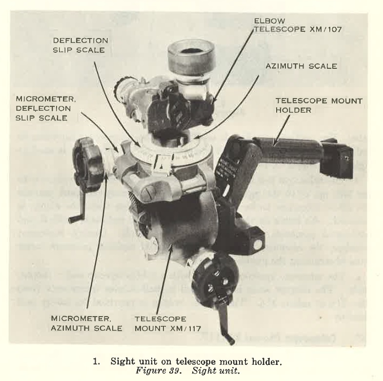
FIGURE 39 - Sight unit on telescope mount holder.
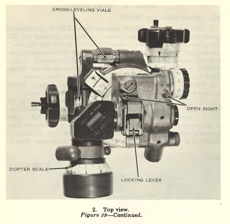
FIGURE 39 - Top View - Cont 39 (2)
d. The telescope can be used in three positions; with the eyepiece to the left, up, or to the right. A clamp on the telescope support permits the elbow telescope to be moved to a new position when the clamp is released. An index on the telescope and support indicates vertical and horizontal positions of cross lines on the reticle. During inclement weather, the eyepiece turned to a horizontal position prevents water from obstructing the gunner's vision.
e. The telescope eyepiece is fitted with a rubber eye cup and a diopter scale. The diopter scale is graduated in half-diopter increments from plus 3½ to minus 3½. The rubber eye cup is provided for safety and comfort.
67. Telescope Mount XMl 17
a. General. The telescope mount consists of three parts. The lower part contains a male dovetail, a locking device, and an elevation knob with scales. The center part has an azimuth knob, stationary and slippable scales, and a pair of cross level vials. The upper part contains an open sight and an angle-of-site knob with scales.
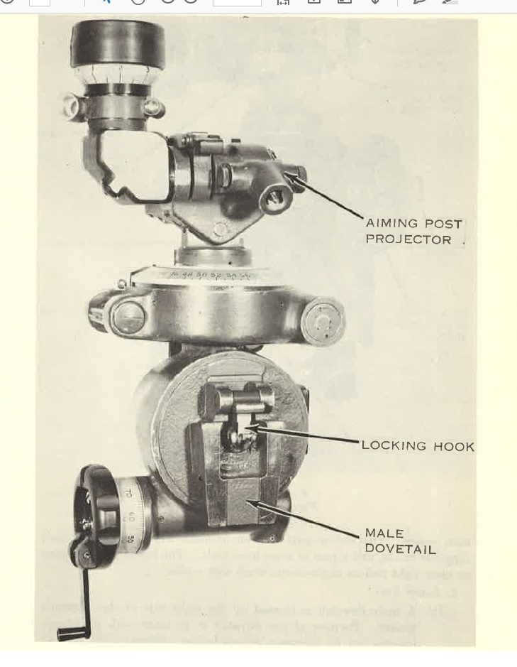
FIGURE 39 - Right side view - Cont 39 (3)
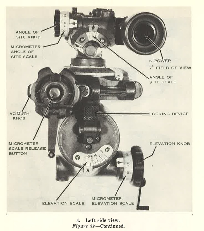
FIGURE 39 - Left side view - Cont 39 (4)
b. Lower Part. (1) A male dovetail is located on the right side of the telescope mount. Purpose of the dovetail is to mate with its female counterpart on telescope mount holder, securing sight unit to weapon.
(2) A dual-purpose locking device is in the lower section of the mount. Purposes of the locking device are to lock the telescope mount to the telescope mount holder, and to break connection between the dovetail parts. The locking device contains a locking hook on the right side of the mount and is operated by a lever on the left side.

FIGURE 40 - Reticle pattern, elbow telescope XM107
(3) The elevation scale is graduated in 100-mil increments from minus 300 to plus 800 and numbered at each 200-mil graduation. The elevation micrometer scale is graduated in 1-mil increments from O to 100 and is numbered at each 10-mil graduation. The micrometer scale is numbered in a clockwise (red scale) and counterclockwise (black scale) direction in order to permit both positive and negative readings.
c. The Center Part.
(1) The azimuth scale (red) fixed to the azimuth shaft is graduated in 100-mil increments from O to 6,400 and is numbered at each 400-mil graduation.
(2) The azimuth micrometer scale (red), also fixed to the azimuth shaft, is graduated in 1-mil increments from O to 100 and is numbered at each 10-mil graduation.
(3) The deflection scale (black) is graduated in 100-mil increments from O to 6,400 and is numbered at each 200-mil graduation. This scale is movable and held in place by friction. It can be rotated with pressure applied downward to the scale.
(4) The deflection micrometer scale (black) is graduated in 1-mil increments from O to 100 and is numbered at each 10-mil graduation. It is kept in place by friction. To release movable micrometer scale, depress micrometer scale release button on end of azimuth knob.
d. The Upper Part.
(1) The upper part consists of an elbow telescope, telescope support with clamp, open sight, angle-of-site knob, angle-of-site scale, and angle-of-site micrometer scale.
(2) The open sight is used to make major changes in deflection for initial lay on or near the target, or when for any reason the elbow telescope cannot be used. The elbow telescope is used for final minor adjustments.
(3) The angle-of-site scale is graduated in 100-mil increments from 0 to 300, plus and minus. It is numbered at the 200-mil graduation. The angle-of-site micrometer scale is graduated in 1-mil increments from Oto 100, and numbered at each 10-mil graduation.
(4) An aiming post projector is located on the telescope support. It can direct a beam of light in direction of line-of-site. The beam is reflected by an aiming post reflector establishing a reference line for fire at night.
68. Instrument Light XM53
The instrument light XM53 (fig. 41) is used to illuminate the sight reticle. Two BA30 cells in their case provide necessary power. A rheostat knob on the battery case turns light on and off or increases or decreases intensity of illumination. The instrument light is packed with the sight assembly in carrying case XM121. When placing instrument light in carrying case, remove batteries from battery case and place in space provided. A hand light is provided, and may be directed upon the scales of the sight unit.
69. Telescope Carrying Case XM121 a. The telescope carrying case is lightweight and provides protective storage for the XM107 elbow telescope, the XMll 7 telescope mount, and the XM53 instrument light. It is fiberglass. b. Clips inside the case hold the instrument light for storage and operation. Clips also hold two spare dry cells. A lamp bracket holds two spare lamps, and a channel-shaped bracket provides a dovetail groove for the telescope mount.
FIGURE 40 - Instrument light XM53
70. Telescope Mount Holders XMS and XM6
a. Telescope mount holders XM5 and XM6 (fig. 42) are aluminum, and are integral parts of the light and heavy barrel assemblies. The mounts are identical except for length.
b. The telescope mount holder consists of a rocker, cross-leveling hand grip, and female dovetail. The hand grip and rocker are fixed to the barrel and may not be detached.
c. The cross-leveling hand grip is fastened to the rocker and a bracket. Rotation of the grip will change the length of the cross-level screw and force the rocker to rotate. Built-in stop rings limit rotation of cross-level screw in extreme positions. A scribe line on the cross-leveling screw indicates center position. A flat coil spring keeps cross-leveling screw under tension, preventing backlash.
d. To correct sight for effects of cant, rotate hand grip of cross-leveling screw. This moves the dovetail bracket, causing the vertical axis of sight to move vertically, irrespective of the position of the barrel. The hand grip of the cross-leveling screw may be turned from center, seven turns either way. Turning the hand grip forward (muzzle) moves sight unit to left; turning hand grip to rear (breech) moves sight unit to right. Cant corrections from + 180 to -180 mils may be made.

FIGURE 42 - Holder, telescope mount XM5 or XM6